2001 NISSAN PICK-UP coolant
[x] Cancel search: coolantPage 126 of 1306
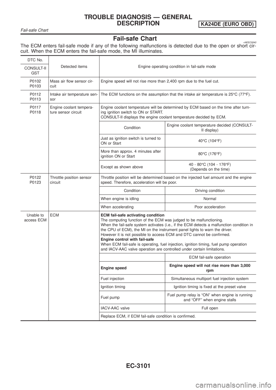
Fail-safe Chart=NEEC0040The ECM enters fail-safe mode if any of the following malfunctions is detected due to the open or short cir-
cuit. When the ECM enters the fail-safe mode, the MI illuminates.
DTC No.
Detected items Engine operating condition in fail-safe mode
CONSULT-II
GST
P0102
P0103Mass air flow sensor cir-
cuitEngine speed will not rise more than 2,400 rpm due to the fuel cut.
P0112
P0113Intake air temperature sen-
sorThe ECM functions on the assumption that the intake air temperature is 25ÉC (77ÉF).
P0117
P0118Engine coolant tempera-
ture sensor circuitEngine coolant temperature will be determined by ECM based on the time after turn-
ing ignition switch to ON or START.
CONSULT-II displays the engine coolant temperature decided by ECM.
ConditionEngine coolant temperature decided (CONSULT-
II display)
Just as ignition switch is turned to
ON or Start40ÉC (104ÉF)
More than approx. 4 minutes after
ignition ON or Start80ÉC (176ÉF)
Except as shown above40 - 80ÉC (104 - 176ÉF)
(Depends on the time)
P0122
P0123Throttle position sensor
circuitThrottle position will be determined based on the injected fuel amount and the engine
speed. Therefore, acceleration will be poor.
Condition Driving condition
When engine is idling Normal
When accelerating Poor acceleration
Unable to
access ECMECMECM fail-safe activating condition
The computing function of the ECM was judged to be malfunctioning.
When the fail-safe system activates (i.e., if the ECM detects a malfunction condition in
the CPU of ECM), the MI on the instrument panel lights to warn the driver.
However it is not possible to access ECM and DTC cannot be confirmed.
Engine control with fail-safe
When ECM fail-safe is operating, fuel injection, ignition timing, fuel pump operation
and IACV-AAC valve operation are controlled under certain limitations.
ECM fail-safe operation
Engine speedEngine speed will not rise more than 3,000
rpm
Fuel injection Simultaneous multiport fuel injection system
Ignition timing Ignition timing is fixed at the preset valve
Fuel pumpFuel pump relay is ªONº when engine is running
and ªOFFº when engine stalls
IACV-AAC valve Full open
Replace ECM, if ECM fail-safe condition is confirmed.
TROUBLE DIAGNOSIS Ð GENERAL
DESCRIPTION
KA24DE (EURO OBD)
Fail-safe Chart
EC-3101
Page 128 of 1306
SYMPTOM
Reference
page
HARD/NO START/RESTART (EXCP. HA)
ENGINE STALL
HESITATION/SURGING/FLAT SPOT
SPARK KNOCK/DETONATION
LACK OF POWER/POOR ACCELERATION
HIGH IDLE/LOW IDLE
ROUGH IDLE/HUNTING
IDLING VIBRATION
SLOW/NO RETURN TO IDLE
OVERHEATS/WATER TEMPERATURE HIGH
EXCESSIVE FUEL CONSUMPTION
EXCESSIVE OIL CONSUMPTION
BATTERY DEAD (UNDER CHARGE)
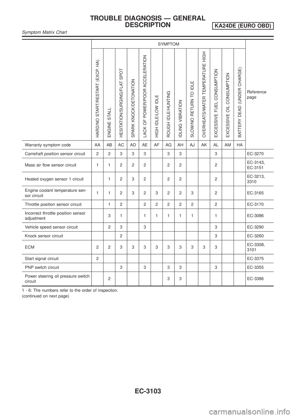
Warranty symptom code AA AB AC AD AE AF AG AH AJ AK AL AM HA
Camshaft position sensor circuit22333 33 3EC-3270
Mass air flow sensor circuit11222 22 2EC-3143,
EC-3151
Heated oxygen sensor 1 circuit1232 22 2EC-3213,
3310
Engine coolant temperature sen-
sor circuit112323223 2EC-3165
Throttle position sensor circuit 1 222222 2EC-3170
Incorrect throttle position sensor
adjustment31 11111 1EC-3086
Vehicle speed sensor circuit 2 3 3 3 EC-3290
Knock sensor circuit 2 3 EC-3260
ECM 22333333333EC-3308,
3101
Start signal circuit 2EC-3375
PNP switch circuit 3 3 3 3 3 EC-3355
Power steering oil pressure switch
circuit2 3 3 EC-3386
1 - 6: The numbers refer to the order of inspection.
(continued on next page)
TROUBLE DIAGNOSIS Ð GENERAL
DESCRIPTION
KA24DE (EURO OBD)
Symptom Matrix Chart
EC-3103
Page 130 of 1306
SYMPTOM
Reference
page
HARD/NO START/RESTART (EXCP. HA)
ENGINE STALL
HESITATION/SURGING/FLAT SPOT
SPARK KNOCK/DETONATION
LACK OF POWER/POOR ACCELERATION
HIGH IDLE/LOW IDLE
ROUGH IDLE/HUNTING
IDLING VIBRATION
SLOW/NO RETURN TO IDLE
OVERHEATS/WATER TEMPERATURE HIGH
EXCESSIVE FUEL CONSUMPTION
EXCESSIVE OIL CONSUMPTION
BATTERY DEAD (UNDER CHARGE)
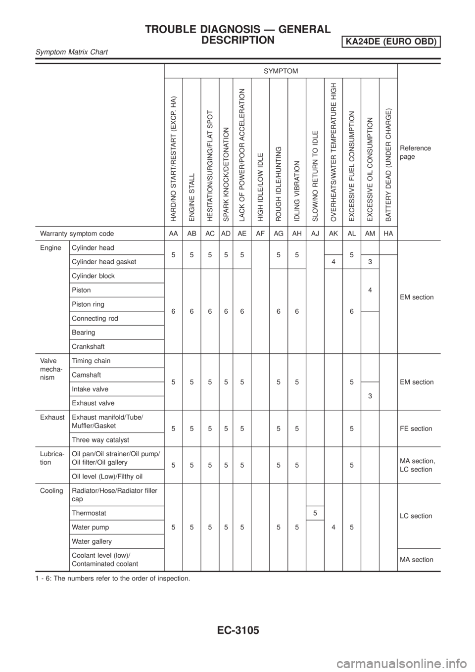
Warranty symptom code AA AB AC AD AE AF AG AH AJ AK AL AM HA
Engine Cylinder head
55555 55 5
EM section Cylinder head gasket 4 3
Cylinder block
66666 66 64 Piston
Piston ring
Connecting rod
Bearing
Crankshaft
Valve
mecha-
nismTiming chain
5 5 5 5 5 5 5 5 EM section Camshaft
Intake valve
3
Exhaust valve
Exhaust Exhaust manifold/Tube/
Muffler/Gasket
5 5 5 5 5 5 5 5 FE section
Three way catalyst
Lubrica-
tionOil pan/Oil strainer/Oil pump/
Oil filter/Oil gallery
55555 55 5MA section,
LC section
Oil level (Low)/Filthy oil
Cooling Radiator/Hose/Radiator filler
cap
55555 55 45LC section Thermostat 5
Water pump
Water gallery
Coolant level (low)/
Contaminated coolantMA section
1 - 6: The numbers refer to the order of inspection.
TROUBLE DIAGNOSIS Ð GENERAL
DESCRIPTION
KA24DE (EURO OBD)
Symptom Matrix Chart
EC-3105
Page 142 of 1306
![NISSAN PICK-UP 2001 Repair Manual TERMI-
NAL
NO.WIRE
COLORITEM CONDITION DATA (DC Voltage)
56 L/WHeated oxygen sensor
2[Engine is running]
+After warming up to normal operating tempera-
ture and revving engine from idle to 3,000 rpm
q NISSAN PICK-UP 2001 Repair Manual TERMI-
NAL
NO.WIRE
COLORITEM CONDITION DATA (DC Voltage)
56 L/WHeated oxygen sensor
2[Engine is running]
+After warming up to normal operating tempera-
ture and revving engine from idle to 3,000 rpm
q](/manual-img/5/57372/w960_57372-141.png)
TERMI-
NAL
NO.WIRE
COLORITEM CONDITION DATA (DC Voltage)
56 L/WHeated oxygen sensor
2[Engine is running]
+After warming up to normal operating tempera-
ture and revving engine from idle to 3,000 rpm
quickly0 - Approximately 1.0V
59 LG/REngine coolant tem-
perature sensor[Engine is running]Approximately 0 - 4.8V
Output voltage varies with
engine coolant temperature
61 P/BIntake air temperature
sensor[Engine is running]Approximately 0 - 4.8V
Output voltage varies with
intake air temperature
64 W Knock sensor[Engine is running]
+Idle speedApproximately 2.4V
67 W
Power supply for ECM[Ignition switch ON]BATTERY VOLTAGE
(11 - 14V)
72 W
69 LG/R Data link connector[Ignition switch ON]
+CONSULT-II or GST is disconnected.Approximately 2V
80 GY/LPower supply (Back-
up)[Ignition switch OFF]BATTERY VOLTAGE
(11 - 14V)
101 G/Y IACV-AAC valve[Engine is running]
+Warm-up condition
+Idle speed10.5 - 11.5V
SEF645U
[Engine is running]
+Warm-up condition
+Engine speed is 2,000 rpm1 - 13V
SEF646U
102 W/L Injector No. 1
[Engine is running]
+Warm-up condition
+Idle speedBATTERY VOLTAGE
(11 - 14V)
SEF204T
104 W/G Injector No. 3
TROUBLE DIAGNOSIS Ð GENERAL
DESCRIPTION
KA24DE (EURO OBD)
ECM Terminals and Reference Value
EC-3117
Page 144 of 1306
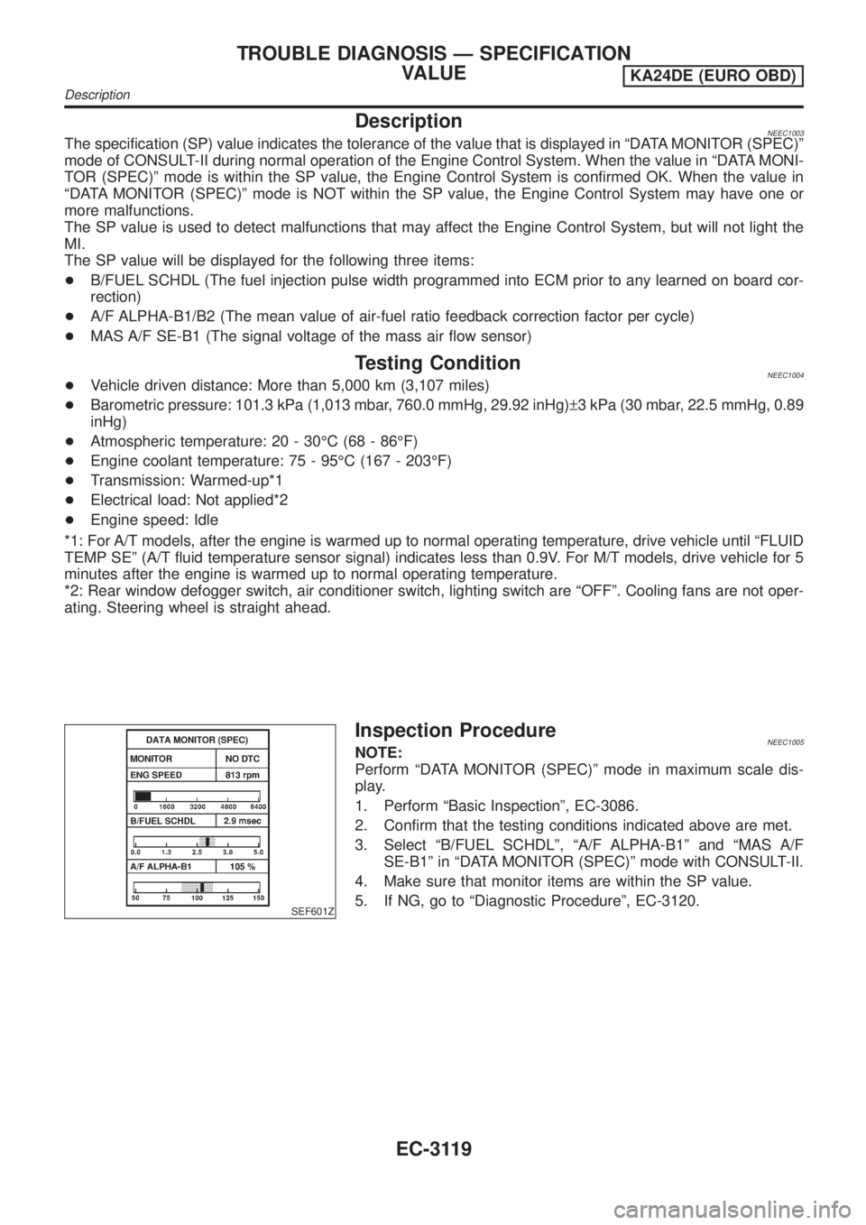
DescriptionNEEC1003The specification (SP) value indicates the tolerance of the value that is displayed in ªDATA MONITOR (SPEC)º
mode of CONSULT-II during normal operation of the Engine Control System. When the value in ªDATA MONI-
TOR (SPEC)º mode is within the SP value, the Engine Control System is confirmed OK. When the value in
ªDATA MONITOR (SPEC)º mode is NOT within the SP value, the Engine Control System may have one or
more malfunctions.
The SP value is used to detect malfunctions that may affect the Engine Control System, but will not light the
MI.
The SP value will be displayed for the following three items:
+B/FUEL SCHDL (The fuel injection pulse width programmed into ECM prior to any learned on board cor-
rection)
+A/F ALPHA-B1/B2 (The mean value of air-fuel ratio feedback correction factor per cycle)
+MAS A/F SE-B1 (The signal voltage of the mass air flow sensor)
Testing ConditionNEEC1004+Vehicle driven distance: More than 5,000 km (3,107 miles)
+Barometric pressure: 101.3 kPa (1,013 mbar, 760.0 mmHg, 29.92 inHg)±3 kPa (30 mbar, 22.5 mmHg, 0.89
inHg)
+Atmospheric temperature: 20 - 30ÉC (68 - 86ÉF)
+Engine coolant temperature: 75 - 95ÉC (167 - 203ÉF)
+Transmission: Warmed-up*1
+Electrical load: Not applied*2
+Engine speed: Idle
*1: For A/T models, after the engine is warmed up to normal operating temperature, drive vehicle until ªFLUID
TEMP SEº (A/T fluid temperature sensor signal) indicates less than 0.9V. For M/T models, drive vehicle for 5
minutes after the engine is warmed up to normal operating temperature.
*2: Rear window defogger switch, air conditioner switch, lighting switch are ªOFFº. Cooling fans are not oper-
ating. Steering wheel is straight ahead.
SEF601Z
Inspection ProcedureNEEC1005NOTE:
Perform ªDATA MONITOR (SPEC)º mode in maximum scale dis-
play.
1. Perform ªBasic Inspectionº, EC-3086.
2. Confirm that the testing conditions indicated above are met.
3. Select ªB/FUEL SCHDLº, ªA/F ALPHA-B1º and ªMAS A/F
SE-B1º in ªDATA MONITOR (SPEC)º mode with CONSULT-II.
4. Make sure that monitor items are within the SP value.
5. If NG, go to ªDiagnostic Procedureº, EC-3120.
TROUBLE DIAGNOSIS Ð SPECIFICATION
VALUE
KA24DE (EURO OBD)
Description
EC-3119
Page 190 of 1306
SEF594K
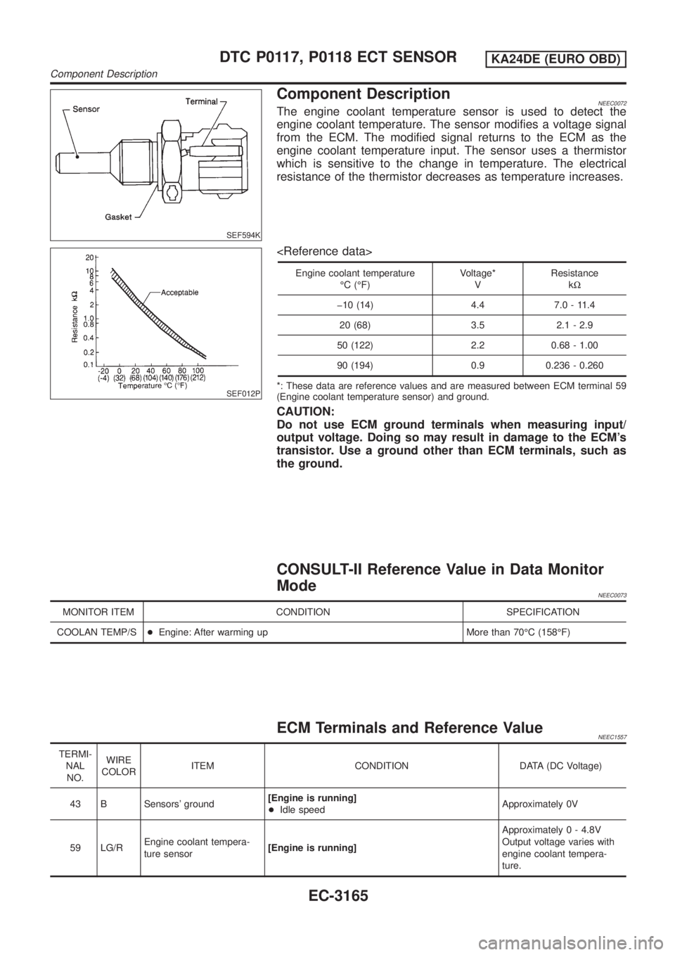
Component DescriptionNEEC0072The engine coolant temperature sensor is used to detect the
engine coolant temperature. The sensor modifies a voltage signal
from the ECM. The modified signal returns to the ECM as the
engine coolant temperature input. The sensor uses a thermistor
which is sensitive to the change in temperature. The electrical
resistance of the thermistor decreases as temperature increases.
SEF012P
Engine coolant temperature
ÉC (ÉF)Voltage*
VResistance
kW
þ10 (14) 4.4 7.0 - 11.4
20 (68) 3.5 2.1 - 2.9
50 (122) 2.2 0.68 - 1.00
90 (194) 0.9 0.236 - 0.260
*: These data are reference values and are measured between ECM terminal 59
(Engine coolant temperature sensor) and ground.
CAUTION:
Do not use ECM ground terminals when measuring input/
output voltage. Doing so may result in damage to the ECM's
transistor. Use a ground other than ECM terminals, such as
the ground.
CONSULT-II Reference Value in Data Monitor
Mode
NEEC0073
MONITOR ITEM CONDITION SPECIFICATION
COOLAN TEMP/S+Engine: After warming up More than 70ÉC (158ÉF)
ECM Terminals and Reference ValueNEEC1557
TERMI-
NAL
NO.WIRE
COLORITEM CONDITION DATA (DC Voltage)
43 B Sensors' ground[Engine is running]
+Idle speedApproximately 0V
59 LG/REngine coolant tempera-
ture sensor[Engine is running]Approximately 0 - 4.8V
Output voltage varies with
engine coolant tempera-
ture.
DTC P0117, P0118 ECT SENSORKA24DE (EURO OBD)
Component Description
EC-3165
Page 191 of 1306
On Board Diagnosis LogicNEEC0074
DTC No.Trouble diag-
nosis nameDTC detecting condition Possible cause
P0117
0117Engine cool-
ant tempera-
ture sensor
circuit low
inputAn excessively low voltage from the sensor is sent
to ECM.+Harness or connectors
(The sensor circuit is open or shorted.)
+Engine coolant temperature sensor
P0118
0118Engine cool-
ant tempera-
ture sensor
circuit high
inputAn excessively high voltage from the sensor is sent
to ECM.
FAIL-SAFE MODENEEC0074S01When the malfunction is detected, the ECM enters fail-safe mode and the MI lights up.
Detected items Engine operating condition in fail-safe mode
Engine coolant tempera-
ture sensor circuitEngine coolant temperature will be determined by ECM based on the time after turning ignition switch
to ON or START.
CONSULT-II displays the engine coolant temperature decided by ECM.
ConditionEngine coolant temperature decided (CONSULT-II
display)
Just as ignition switch is turned to ON or Start 40ÉC (104ÉF)
More than approx. 4 minutes after ignition ON or
Start80ÉC (176ÉF)
Except as shown above40 - 80ÉC (104 - 176ÉF)
(Depends on the time)
SEF058Y
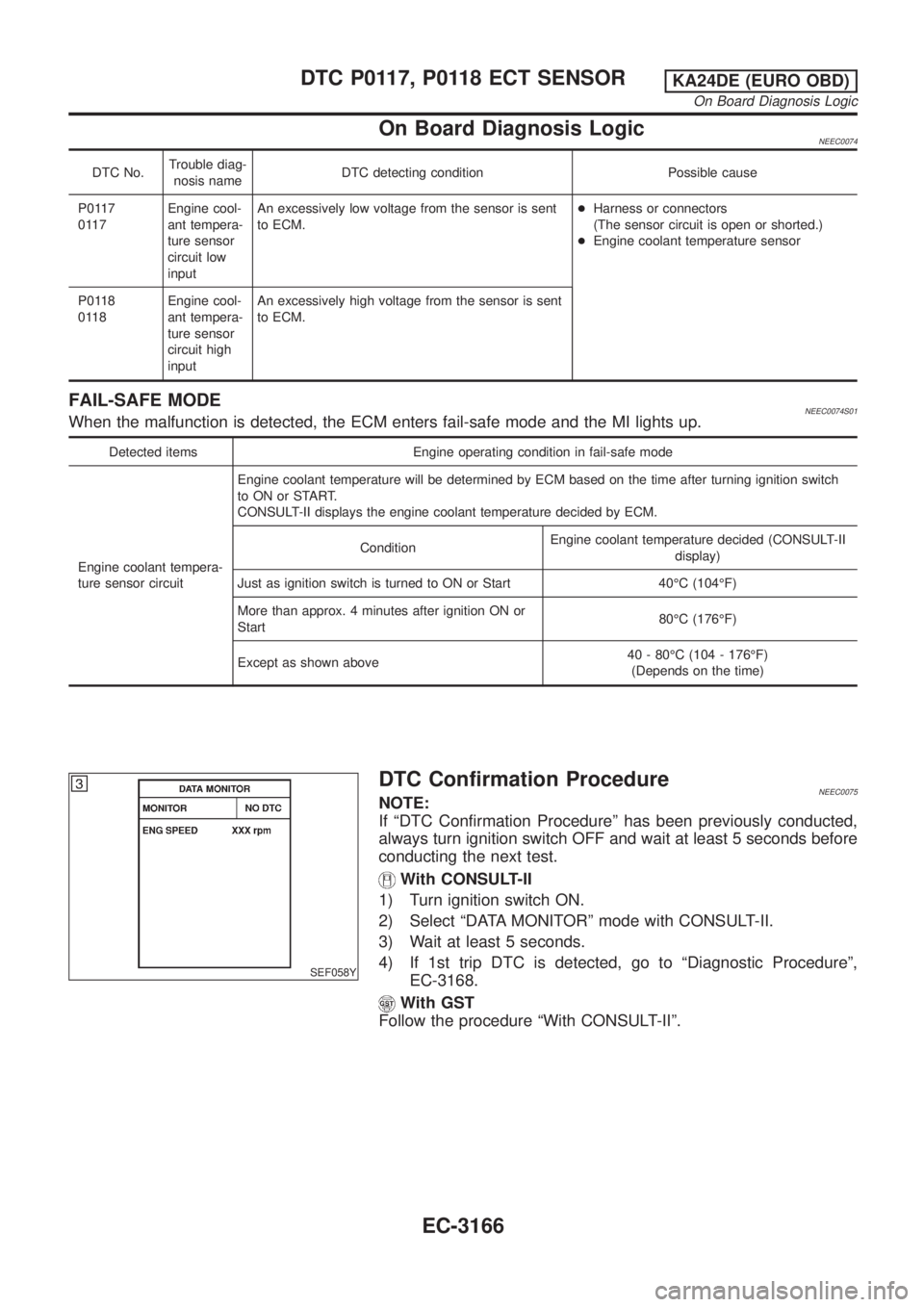
DTC Confirmation ProcedureNEEC0075NOTE:
If ªDTC Confirmation Procedureº has been previously conducted,
always turn ignition switch OFF and wait at least 5 seconds before
conducting the next test.
With CONSULT-II
1) Turn ignition switch ON.
2) Select ªDATA MONITORº mode with CONSULT-II.
3) Wait at least 5 seconds.
4) If 1st trip DTC is detected, go to ªDiagnostic Procedureº,
EC-3168.
With GST
Follow the procedure ªWith CONSULT-IIº.
DTC P0117, P0118 ECT SENSORKA24DE (EURO OBD)
On Board Diagnosis Logic
EC-3166
Page 193 of 1306
Diagnostic ProcedureNEEC0077
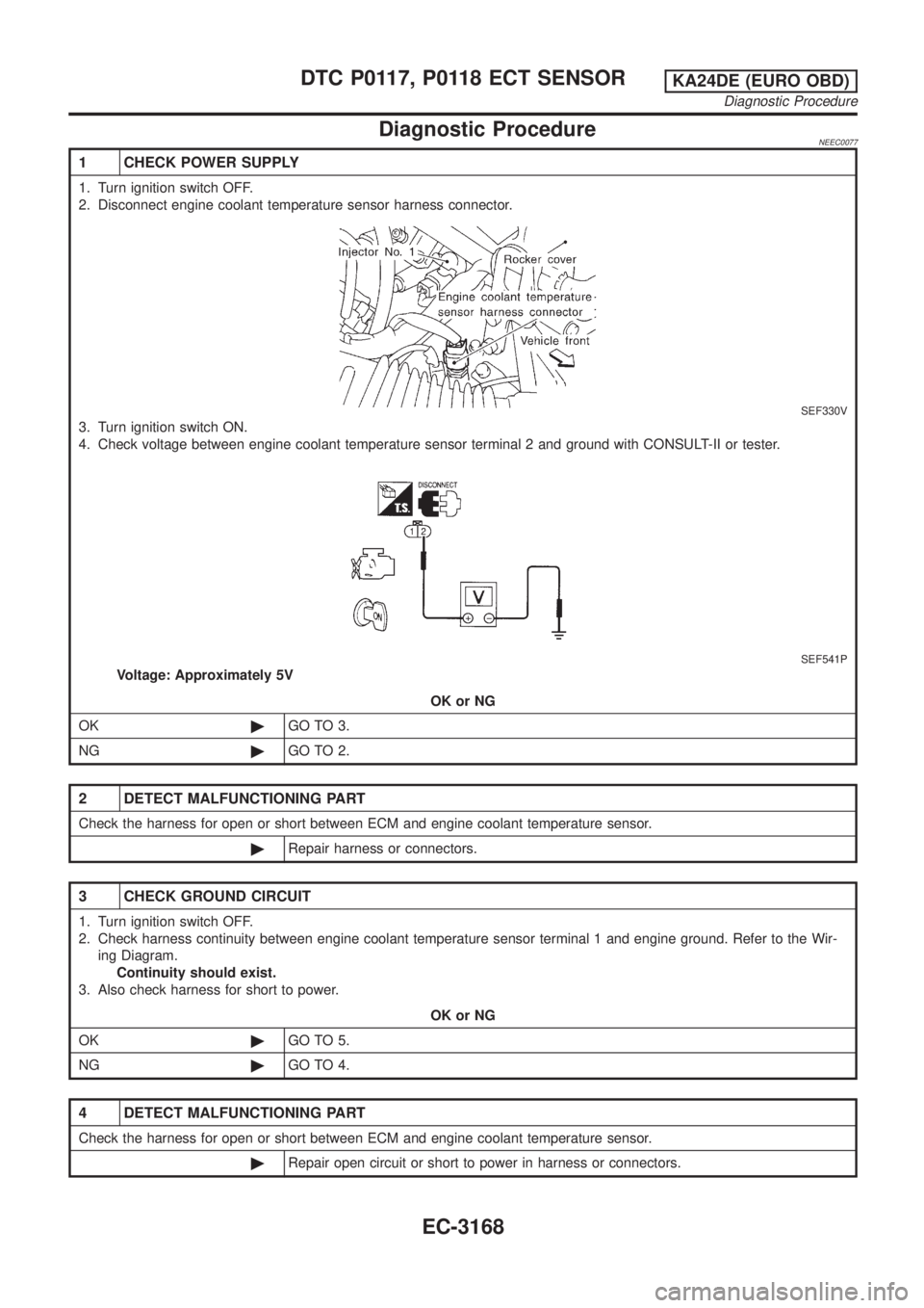
1 CHECK POWER SUPPLY
1. Turn ignition switch OFF.
2. Disconnect engine coolant temperature sensor harness connector.
SEF330V
3. Turn ignition switch ON.
4. Check voltage between engine coolant temperature sensor terminal 2 and ground with CONSULT-II or tester.
SEF541P
Voltage: Approximately 5V
OK or NG
OK©GO TO 3.
NG©GO TO 2.
2 DETECT MALFUNCTIONING PART
Check the harness for open or short between ECM and engine coolant temperature sensor.
©Repair harness or connectors.
3 CHECK GROUND CIRCUIT
1. Turn ignition switch OFF.
2. Check harness continuity between engine coolant temperature sensor terminal 1 and engine ground. Refer to the Wir-
ing Diagram.
Continuity should exist.
3. Also check harness for short to power.
OK or NG
OK©GO TO 5.
NG©GO TO 4.
4 DETECT MALFUNCTIONING PART
Check the harness for open or short between ECM and engine coolant temperature sensor.
©Repair open circuit or short to power in harness or connectors.
DTC P0117, P0118 ECT SENSORKA24DE (EURO OBD)
Diagnostic Procedure
EC-3168