2001 NISSAN PICK-UP coolant
[x] Cancel search: coolantPage 53 of 1306

Air Conditioning Cut Control
DESCRIPTION=NEEC0016Input/Output Signal ChartNEEC0016S01
Sensor Input Signal to ECMECM func-
tionActuator
Air conditioner switch Air conditioner ªONº signal
Air condi-
tioner cut
controlAir conditioner relay Throttle position sensor Throttle valve opening angle
Camshaft position sensor Engine speed
Engine coolant temperature sensor Engine coolant temperature
Ignition switch Start signal
Vehicle speed sensor Vehicle speed
Power steering oil pressure switch Power steering operation
System DescriptionNEEC0016S02This system improves engine operation when the air conditioner is used.
Under the following conditions, the air conditioner is turned off.
+When the accelerator pedal is fully depressed.
+When cranking the engine.
+When the engine coolant temperature becomes excessively high.
+When operating power steering and air conditioner during low engine speed or when fully releasing accel-
erator pedal.
+When engine speed is excessively low.
Fuel Cut Control (at no load & high engine
speed)
DESCRIPTIONNEEC0017Input/Output Signal ChartNEEC0017S01
Sensor Input Signal to ECMECM func-
tionActuator
Vehicle speed sensor Vehicle speed
Fuel cut
controlInjectors PNP switch Neutral position
Throttle position sensor Throttle position
Camshaft position sensor Engine speed
If the engine speed is above 3,000 rpm with no load, (for example, in Neutral and engine speed over 3,000
rpm) fuel will be cut off after some time. The exact time when the fuel is cut off varies based on engine speed.
Fuel cut will operate until the engine speed reaches 1,500 rpm, then fuel cut is cancelled.
NOTE:
This function is different from deceleration control listed under ªMultiport Fuel Injection (MFI) Systemº,
EC-3024.
ENGINE AND EMISSION BASIC CONTROL SYSTEM
DESCRIPTION
KA24DE (EURO OBD)
Air Conditioning Cut Control
EC-3028
Page 60 of 1306

SEF500V
Fast Idle Cam (FIC)
COMPONENT DESCRIPTIONNEEC0502The FIC is installed on the throttle body to maintain adequate
engine speed while the engine is cold. It is operated by a volumet-
ric change in wax located inside the thermo-element. The thermo-
element is operated by engine coolant temperature.
For inspection refer to ªTROUBLE DIAGNOSIS-BASIC
INSPECTIONº, ªBasic Inspectionº, EC-3086.
Idle Speed/Ignition Timing/Idle Mixture Ratio
Adjustment
NEEC0028PREPARATIONNEEC0028S05+Make sure that the following parts are in good order.
a)Battery
b)Ignition system
c)Engine oil and coolant levels
d)Fuses
e)ECM harness connector
f)Vacuum hoses
g)Air intake system
(Oil filler cap, oil level gauge, etc.)
h)Fuel pressure
i)Engine compression
j)Throttle valve
k)EVAP system
+On models equipped with air conditioner, checks should be carried out while the air conditioner is
ªOFFº.
+When measuring ªCOº percentage, insert probe more than 40 cm (15.7 in) into tail pipe.
+Turn off headlamps, heater blower.
+Keep front wheels pointed straight ahead.
BASIC SERVICE PROCEDUREKA24DE (EURO OBD)
Fast Idle Cam (FIC)
EC-3035
Page 62 of 1306
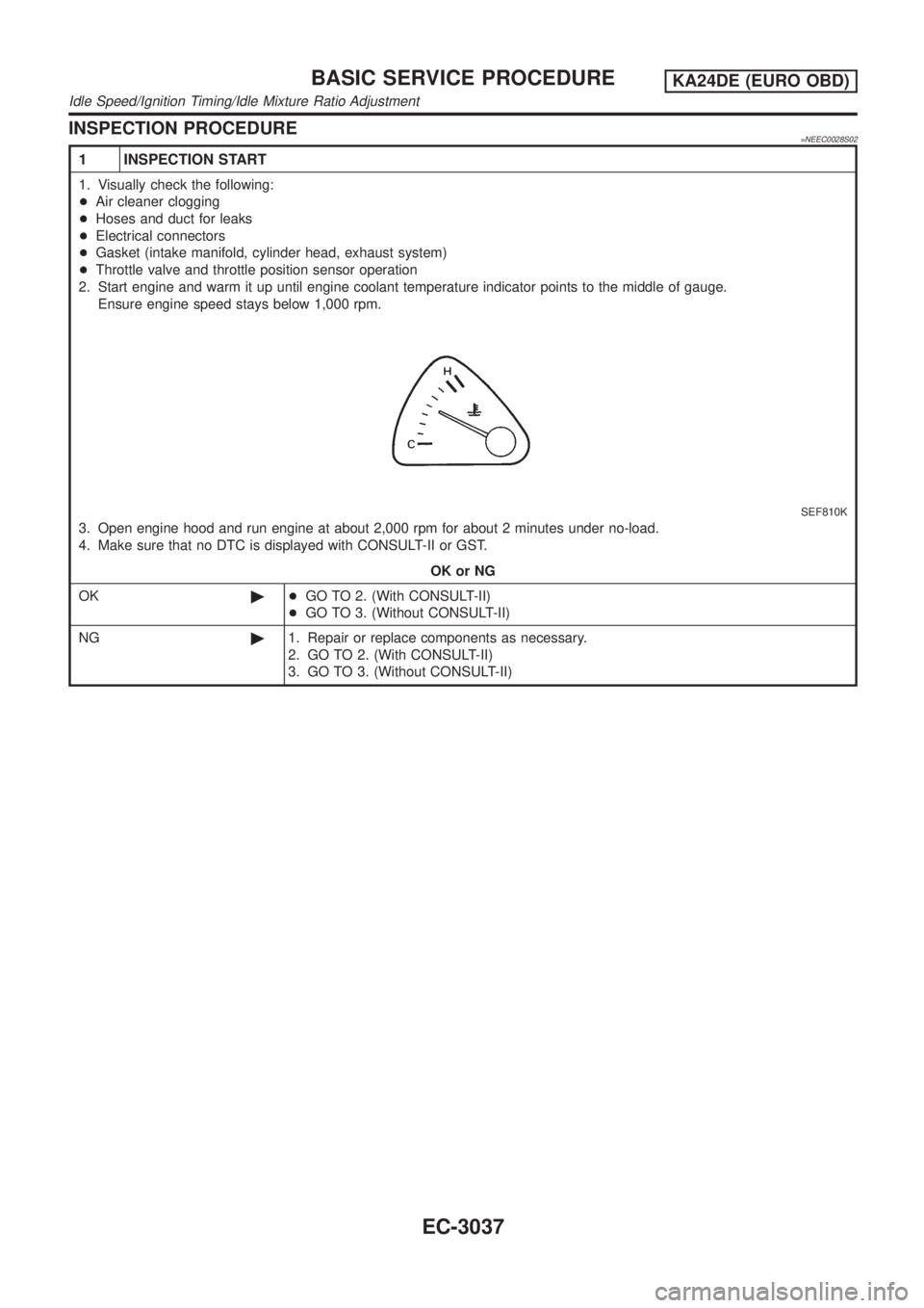
INSPECTION PROCEDURE=NEEC0028S02
1 INSPECTION START
1. Visually check the following:
+Air cleaner clogging
+Hoses and duct for leaks
+Electrical connectors
+Gasket (intake manifold, cylinder head, exhaust system)
+Throttle valve and throttle position sensor operation
2. Start engine and warm it up until engine coolant temperature indicator points to the middle of gauge.
Ensure engine speed stays below 1,000 rpm.
SEF810K
3. Open engine hood and run engine at about 2,000 rpm for about 2 minutes under no-load.
4. Make sure that no DTC is displayed with CONSULT-II or GST.
OK or NG
OK©+GO TO 2. (With CONSULT-II)
+GO TO 3. (Without CONSULT-II)
NG©1. Repair or replace components as necessary.
2. GO TO 2. (With CONSULT-II)
3. GO TO 3. (Without CONSULT-II)
BASIC SERVICE PROCEDUREKA24DE (EURO OBD)
Idle Speed/Ignition Timing/Idle Mixture Ratio Adjustment
EC-3037
Page 71 of 1306
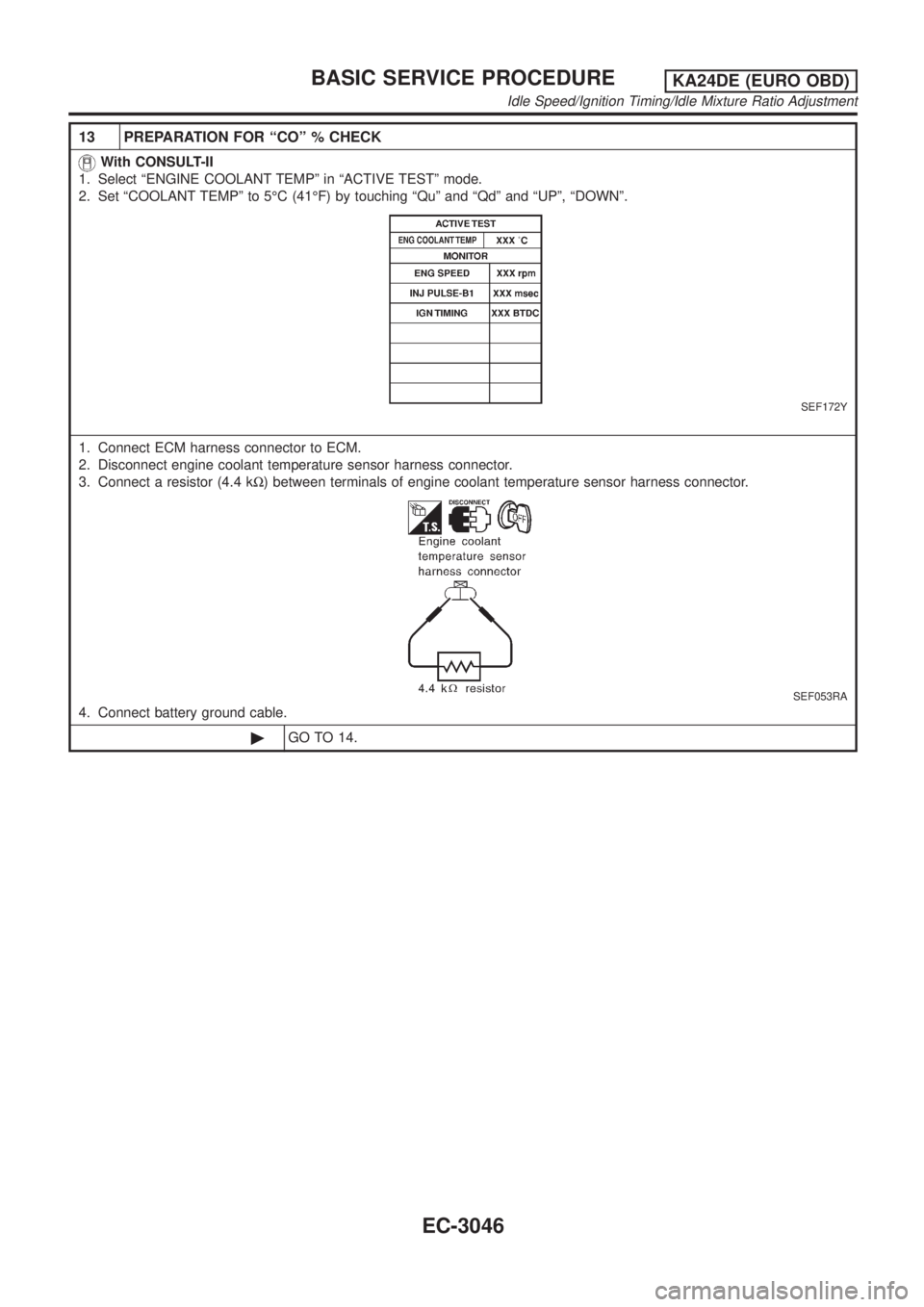
13 PREPARATION FOR ªCOº % CHECK
With CONSULT-II
1. Select ªENGINE COOLANT TEMPº in ªACTIVE TESTº mode.
2. Set ªCOOLANT TEMPº to 5ÉC (41ÉF) by touching ªQuº and ªQdº and ªUPº, ªDOWNº.
SEF172Y
1. Connect ECM harness connector to ECM.
2. Disconnect engine coolant temperature sensor harness connector.
3. Connect a resistor (4.4 kW) between terminals of engine coolant temperature sensor harness connector.
SEF053RA
4. Connect battery ground cable.
©GO TO 14.
BASIC SERVICE PROCEDUREKA24DE (EURO OBD)
Idle Speed/Ignition Timing/Idle Mixture Ratio Adjustment
EC-3046
Page 72 of 1306
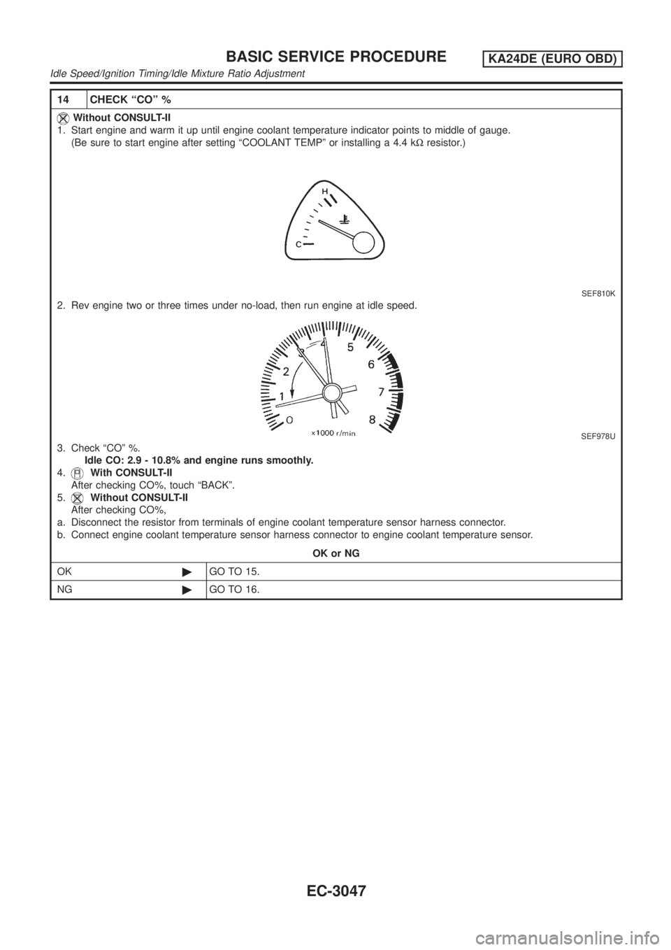
14 CHECK ªCOº %
Without CONSULT-II
1. Start engine and warm it up until engine coolant temperature indicator points to middle of gauge.
(Be sure to start engine after setting ªCOOLANT TEMPº or installing a 4.4 kWresistor.)
SEF810K
2. Rev engine two or three times under no-load, then run engine at idle speed.
SEF978U
3. Check ªCOº %.
Idle CO: 2.9 - 10.8% and engine runs smoothly.
4.
With CONSULT-II
After checking CO%, touch ªBACKº.
5.
Without CONSULT-II
After checking CO%,
a. Disconnect the resistor from terminals of engine coolant temperature sensor harness connector.
b. Connect engine coolant temperature sensor harness connector to engine coolant temperature sensor.
OK or NG
OK©GO TO 15.
NG©GO TO 16.
BASIC SERVICE PROCEDUREKA24DE (EURO OBD)
Idle Speed/Ignition Timing/Idle Mixture Ratio Adjustment
EC-3047
Page 73 of 1306
15 CHECK HEATED OXYGEN SENSOR 1 SIGNAL
With CONSULT-II
1. Replace heated oxygen sensor 1.
2. See ªHO2S1 MNTR (B1)º in ªDATA MONITORº mode.
3. Maintain engine at 2,000 rpm under no-load (engine is warmed up to normal operating temperature.). Check that the
monitor fluctuates between ªLEANº and ªRICHº more than five times during 10 seconds.
1 cycle: RICH®LEAN®RICH
2 cycles: RICH®LEAN®RICH®LEAN®RICH
Without CONSULT-II
1. Stop engine.
2. Replace heated oxygen sensor 1.
3. Start engine and warm it up to normal operating temperature.
4. Run engine at approx. 2,000 rpm for approx. 2 minutes under no-load.
5. Set voltmeter probe between ECM terminal 50 and ground.
6. Make sure that voltage fluctuates between 0 - 0.3V and 0.6 - 1.0V more than 5 times during 10 seconds at 2,000 rpm.
1 time: 0 - 0.3V®0.6 - 1.0V®0 - 0.3V
2 times: 0 - 0.3V®0.6 - 1.0V®0 - 0.3V®0.6 - 1.0V®0 - 0.3V
OK or NG
OK©GO TO 12.
NG©GO TO 16.
16 DETECT MALFUNCTIONING PART
1. Connect heated oxygen sensor 1 harness connector to heated oxygen sensor 1.
2. Check fuel pressure regulator. Refer to EC-3034.
3. Check mass air flow sensor and its circuit.
Refer to EC-3143, EC-3151.
4. Check injector and its circuit.
Refer to EC-3369.
Clean or replace if necessary.
5. Check engine coolant temperature sensor and its circuit. Refer to EC-3165.
6. Check ECM function by substituting another known-good ECM.
(ECM may be the cause of a problem, but this is rarely the case.)
©GO TO 12.
+If a vehicle contains a part which is operating outside of design specifications with no MI
illumination, the part shall not be replaced prior to emission testing unless it is determined that
the part has been tampered with or abused in such a way that the diagnostic system cannot rea-
sonably be expected to detect the resulting malfunction.
BASIC SERVICE PROCEDUREKA24DE (EURO OBD)
Idle Speed/Ignition Timing/Idle Mixture Ratio Adjustment
EC-3048
Page 75 of 1306
trip (meeting the required driving pattern), the 1st trip DTC is cleared from the ECM memory. If the same mal-
function is detected in the 2nd trip, both the 1st trip DTC and DTC are stored in the ECM memory and the MI
lights up. In other words, the DTC is stored in the ECM memory and the MI lights up when the same malfunc-
tion occurs in two consecutive trips. If a 1st trip DTC is stored and a non-diagnostic operation is performed
between the 1st and 2nd trips, only the 1st trip DTC will continue to be stored. For malfunctions that blink or
light up the MI during the 1st trip, the DTC and 1st trip DTC are stored in the ECM memory.
Procedures for clearing the DTC and the 1st trip DTC from the ECM memory are described in ªHOW TO
ERASE EMISSION-RELATED DIAGNOSTIC INFORMATIONº. Refer to EC-3060.
For malfunctions in which 1st trip DTCs are displayed, refer to EC-3058. These items are required by legal
regulations to continuously monitor the system/component. In addition, the items monitored non-continuously
are also displayed on CONSULT-II.
1st trip DTC is specified in Mode 7 of ISO 15031-5. 1st trip DTC detection occurs without lighting up the MI
and therefore does not warn the driver of a problem. However, 1st trip DTC detection will not prevent the
vehicle from being tested, for example during Inspection/Maintenance (I/M) tests.
When a 1st trip DTC is detected, check, print out or write down and erase (1st trip) DTC and Freeze Frame
data as specified in ªWork Flowº procedure Step II, refer to page EC-3084. Then perform ªDTC Confirmation
Procedureº or ªOverall Function Checkº to try to duplicate the problem. If the malfunction is duplicated, the
item requires repair.
How to read DTC and 1st Trip DTCNEEC0031S0101DTC and 1st trip DTC can be read by the following methods.
With CONSULT-II
With GST
CONSULT-II or GST (Generic Scan Tool) Examples: P0340 etc.
These DTCs are prescribed by ISO 15031-5.
(CONSULT-II also displays the malfunctioning component or system.)
+1st trip DTC No. is the same as DTC No.
+Output of a DTC indicates a malfunction. However, GST does not indicate whether the malfunction
is still occurring or has occurred in the past and has returned to normal.
CONSULT-II can identify malfunction status as shown below. Therefore, using CONSULT-II (if avail-
able) is recommended.
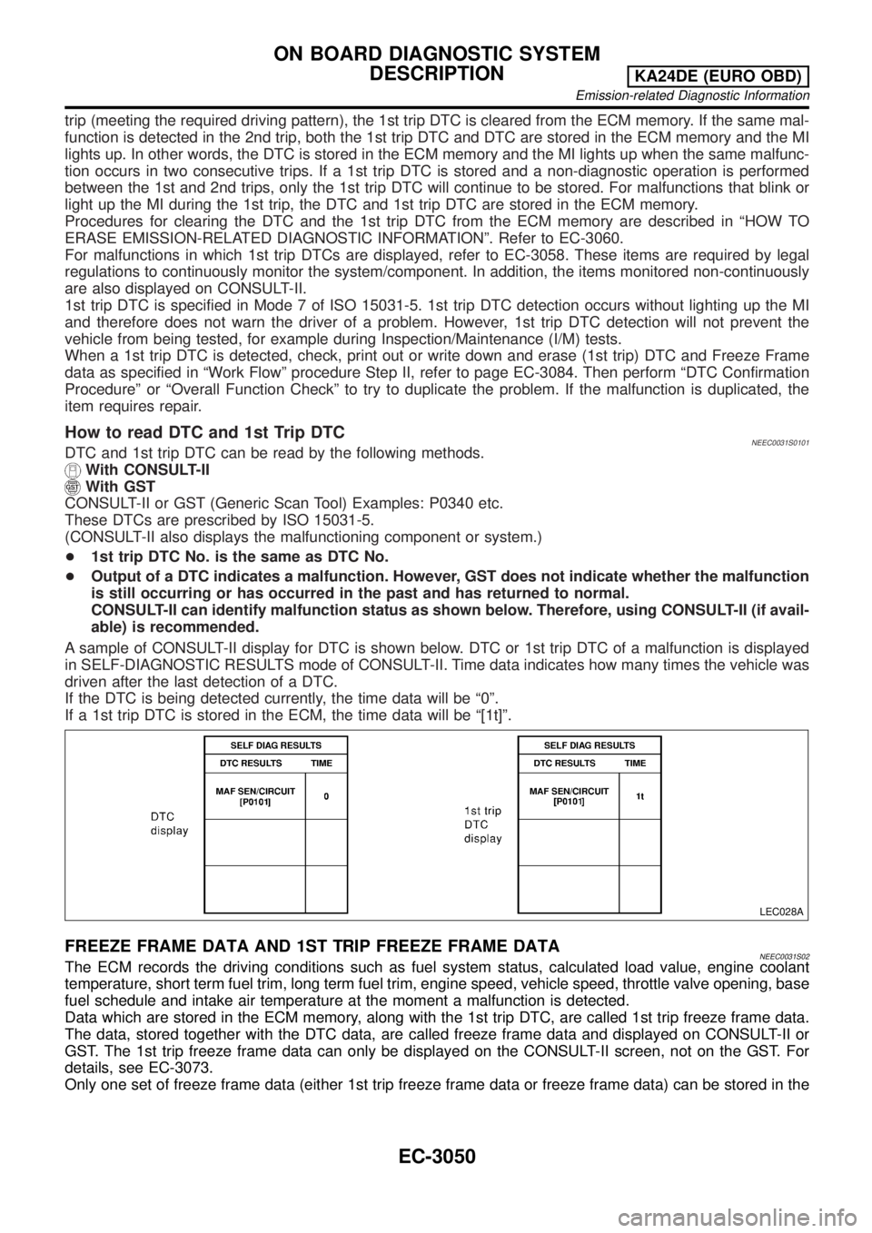
A sample of CONSULT-II display for DTC is shown below. DTC or 1st trip DTC of a malfunction is displayed
in SELF-DIAGNOSTIC RESULTS mode of CONSULT-II. Time data indicates how many times the vehicle was
driven after the last detection of a DTC.
If the DTC is being detected currently, the time data will be ª0º.
If a 1st trip DTC is stored in the ECM, the time data will be ª[1t]º.
LEC028A
FREEZE FRAME DATA AND 1ST TRIP FREEZE FRAME DATANEEC0031S02The ECM records the driving conditions such as fuel system status, calculated load value, engine coolant
temperature, short term fuel trim, long term fuel trim, engine speed, vehicle speed, throttle valve opening, base
fuel schedule and intake air temperature at the moment a malfunction is detected.
Data which are stored in the ECM memory, along with the 1st trip DTC, are called 1st trip freeze frame data.
The data, stored together with the DTC data, are called freeze frame data and displayed on CONSULT-II or
GST. The 1st trip freeze frame data can only be displayed on the CONSULT-II screen, not on the GST. For
details, see EC-3073.
Only one set of freeze frame data (either 1st trip freeze frame data or freeze frame data) can be stored in the
ON BOARD DIAGNOSTIC SYSTEM
DESCRIPTION
KA24DE (EURO OBD)
Emission-related Diagnostic Information
EC-3050
Page 82 of 1306
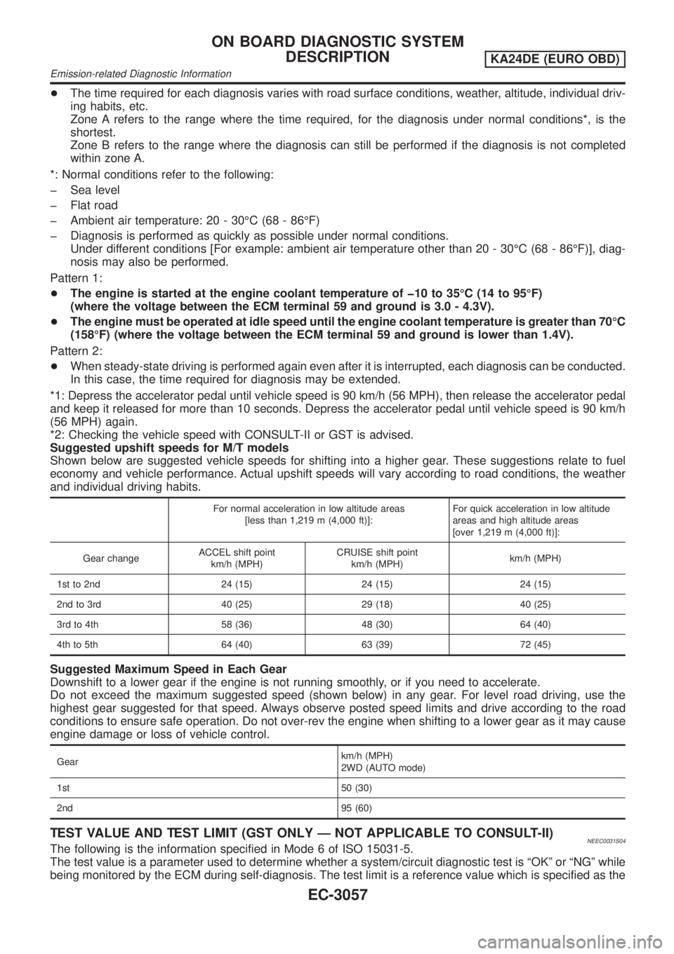
+The time required for each diagnosis varies with road surface conditions, weather, altitude, individual driv-
ing habits, etc.
Zone A refers to the range where the time required, for the diagnosis under normal conditions*, is the
shortest.
Zone B refers to the range where the diagnosis can still be performed if the diagnosis is not completed
within zone A.
*: Normal conditions refer to the following:
þ Sea level
þ Flat road
þ Ambient air temperature: 20 - 30ÉC (68 - 86ÉF)
þ Diagnosis is performed as quickly as possible under normal conditions.
Under different conditions [For example: ambient air temperature other than 20 - 30ÉC (68 - 86ÉF)], diag-
nosis may also be performed.
Pattern 1:
+The engine is started at the engine coolant temperature of þ10 to 35ÉC (14 to 95ÉF)
(where the voltage between the ECM terminal 59 and ground is 3.0 - 4.3V).
+The engine must be operated at idle speed until the engine coolant temperature is greater than 70ÉC
(158ÉF) (where the voltage between the ECM terminal 59 and ground is lower than 1.4V).
Pattern 2:
+When steady-state driving is performed again even after it is interrupted, each diagnosis can be conducted.
In this case, the time required for diagnosis may be extended.
*1: Depress the accelerator pedal until vehicle speed is 90 km/h (56 MPH), then release the accelerator pedal
and keep it released for more than 10 seconds. Depress the accelerator pedal until vehicle speed is 90 km/h
(56 MPH) again.
*2: Checking the vehicle speed with CONSULT-II or GST is advised.
Suggested upshift speeds for M/T models
Shown below are suggested vehicle speeds for shifting into a higher gear. These suggestions relate to fuel
economy and vehicle performance. Actual upshift speeds will vary according to road conditions, the weather
and individual driving habits.
For normal acceleration in low altitude areas
[less than 1,219 m (4,000 ft)]:For quick acceleration in low altitude
areas and high altitude areas
[over 1,219 m (4,000 ft)]:
Gear changeACCEL shift point
km/h (MPH)CRUISE shift point
km/h (MPH)km/h (MPH)
1st to 2nd 24 (15) 24 (15) 24 (15)
2nd to 3rd 40 (25) 29 (18) 40 (25)
3rd to 4th 58 (36) 48 (30) 64 (40)
4th to 5th 64 (40) 63 (39) 72 (45)
Suggested Maximum Speed in Each Gear
Downshift to a lower gear if the engine is not running smoothly, or if you need to accelerate.
Do not exceed the maximum suggested speed (shown below) in any gear. For level road driving, use the
highest gear suggested for that speed. Always observe posted speed limits and drive according to the road
conditions to ensure safe operation. Do not over-rev the engine when shifting to a lower gear as it may cause
engine damage or loss of vehicle control.
Gearkm/h (MPH)
2WD (AUTO mode)
1st 50 (30)
2nd 95 (60)
TEST VALUE AND TEST LIMIT (GST ONLY Ð NOT APPLICABLE TO CONSULT-II)NEEC0031S04The following is the information specified in Mode 6 of ISO 15031-5.
The test value is a parameter used to determine whether a system/circuit diagnostic test is ªOKº or ªNGº while
being monitored by the ECM during self-diagnosis. The test limit is a reference value which is specified as the
ON BOARD DIAGNOSTIC SYSTEM
DESCRIPTION
KA24DE (EURO OBD)
Emission-related Diagnostic Information
EC-3057