Page 360 of 1306

SEC340D
DTC Confirmation ProcedureNEEC0157
SEC341D
SEC342D
CAUTION:
Always drive vehicle at a safe speed.
NOTE:
+ªCOMPLETEDº will appear on CONSULT-II screen when all
tests ªCOND1º, ªCOND2º and ªCOND3º are completed.
+If ªDTC Confirmation Procedureº has been previously
conducted, always turn ignition switch ªOFFº and wait at least
5 seconds before conducting the next test.
TESTING CONDITION:
Never stop engine during this procedure. If the engine is
stopped, retry this procedure from step 2 in ªProcedure for
COND1º.
WITH CONSULT-IINEEC0157S01Procedure for COND1NEEC0157S01011. Start engine and warm it up to normal operating temperature.
2. Turn ignition switch ªOFFº and wait at least 5 seconds.
3. Turn ignition switch ªONº and select ªHO2S2 (B1) P1147º of
ªHO2S2º in ªDTC WORK SUPPORTº mode with CONSULT-II.
4. Touch ªSTARTº.
5. Start engine and let it idle for at least 30 seconds.
6. Rev engine up to 2,000 rpm 2 or 3 times quickly under no load.
If ªCOMPLETEDº appears on CONSULT-II screen, go to step
2 in ªProcedure for COND3º.
If ªCOMPLETEDº does not appear on CONSULT-II screen, go
to the following step.
7. Drive vehicle at a speed of more than 70 km/h (43 MPH) for 2
consecutive minutes.
8. When the following conditions are met, ªTESTINGº will be dis-
played at ªCOND1º on the CONSULT-II screen. Maintain the
conditions continuously until ªTESTINGº changes to ªCOM-
PLETEDº. (It will take approximately 60 seconds.)
ENG SPEED More than 1,000 rpm
B/FUEL SCHDL More than 1.0 msec
COOLANT TEMP/S 70 - 105ÉC
Selector level Suitable position
NOTE:
+If ªTESTINGº is not displayed after 5 minutes, retry from
step 2 in ªProcedure for COND1º.
+If ªCOMPLETEDº already appears at ªCOND2º on CON-
SULT-II screen before ªProcedure for COND2º is
conducted, it is unnecessary to conduct step 1 in ªProce-
dure for COND2º.
DTC P1147 HO2S2KA24DE (EURO OBD)
DTC Confirmation Procedure
EC-3335
Page 369 of 1306
On Board Diagnosis LogicNEEC1534If the cooling fan or another component in the cooling system malfunctions, engine coolant temperature will
rise.
When the engine coolant temperature reaches an abnormally high temperature condition, a malfunction is
indicated.
DTC No. Malfunction is detected when ...Check Items
(Possible Cause)
P1217
1217+Engine coolant temperature reaches an abnormally high
temperature.+Cooling fan (crankshaft driven)
Radiator hose
+Radiator
+Radiator cap
+Water pump
+Thermostat
+Engine coolant temperature sensor
For more information, refer to ªMAIN 11 CAUSES
OF OVERHEATINGº, EC-3348.
CAUTION:
When a malfunction is indicated, be sure to replace the coolant. Refer to MA section, ªChanging Engine
Coolantº. Also, replace the engine oil.
1) Fill radiator with coolant up to specified level with a filling speed of 2 liters per minute. Be sure
to use coolant with the proper mixture ratio. Refer to MA section, ªAnti-freeze Coolant Mixture
Ratioº.
2) After refilling coolant, run engine to ensure that no water-flow noise is emitted.
SEF621W
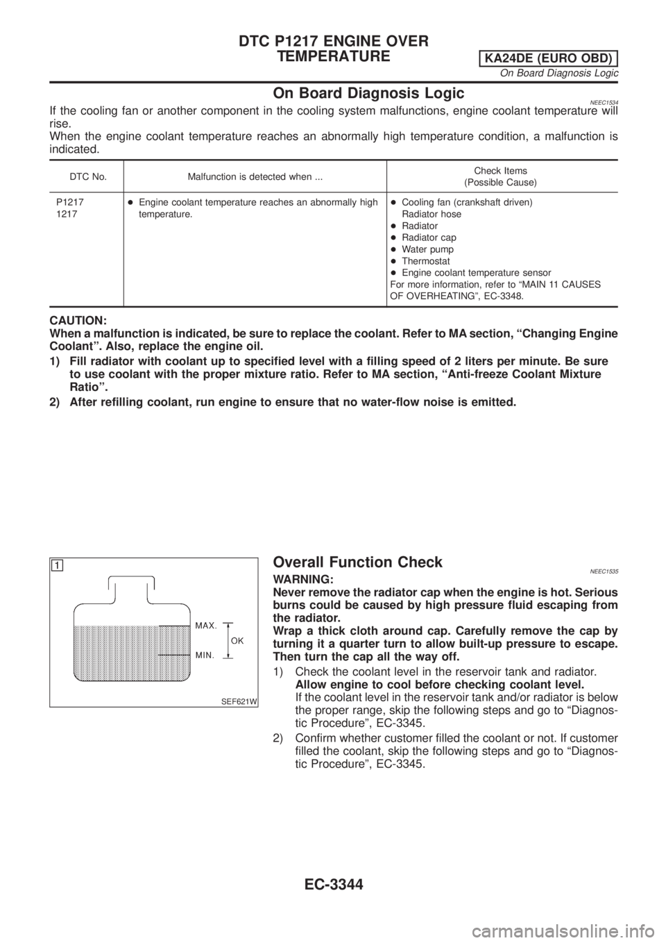
Overall Function CheckNEEC1535WARNING:
Never remove the radiator cap when the engine is hot. Serious
burns could be caused by high pressure fluid escaping from
the radiator.
Wrap a thick cloth around cap. Carefully remove the cap by
turning it a quarter turn to allow built-up pressure to escape.
Then turn the cap all the way off.
1) Check the coolant level in the reservoir tank and radiator.
Allow engine to cool before checking coolant level.
If the coolant level in the reservoir tank and/or radiator is below
the proper range, skip the following steps and go to ªDiagnos-
tic Procedureº, EC-3345.
2) Confirm whether customer filled the coolant or not. If customer
filled the coolant, skip the following steps and go to ªDiagnos-
tic Procedureº, EC-3345.
DTC P1217 ENGINE OVER
TEMPERATURE
KA24DE (EURO OBD)
On Board Diagnosis Logic
EC-3344
Page 372 of 1306
4 CHECK ENGINE COOLANT TEMPERATURE SENSOR
Check resistance as shown in the figure.
SEF152P
MTBL0285
SEF012P
OK or NG
OK©GO TO 5.
NG©Replace engine coolant temperature sensor.
5 CHECK MAIN 11 CAUSES
If the cause cannot be isolated, go to ªMAIN 11 CAUSES OF OVERHEATINGº, EC-3348.
©INSPECTION END
Perform FINAL CHECK by the following procedure after repair
is completed.
1. Warm up engine. Run the vehicle for at least 20 minutes. Pay
attention to engine coolant temperature gauge on the instru-
ment panel. If the reading shows an abnormally high
temperature, another part may be malfunctioning.
2. Stop vehicle and let engine idle. Check the intake and exhaust
systems for leaks by listening for noise or visually inspecting
the components.
3. Allow engine to cool and visually check for oil and coolant
leaks. Then, perform ªOVERALL FUNCTION CHECKº.
DTC P1217 ENGINE OVER
TEMPERATURE
KA24DE (EURO OBD)
Diagnostic Procedure
EC-3347
Page 373 of 1306
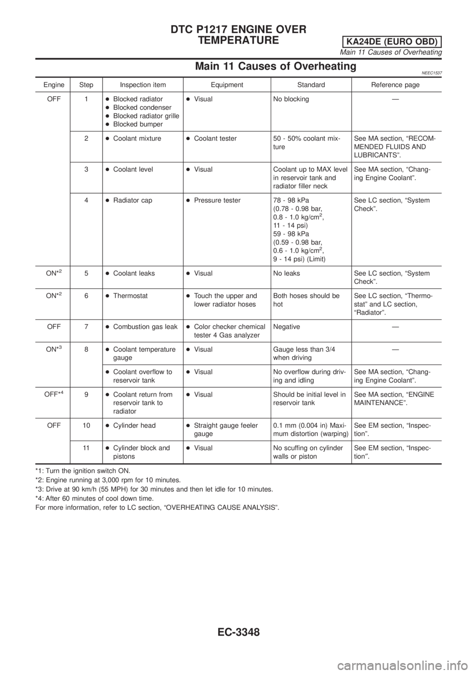
Main 11 Causes of OverheatingNEEC1537
Engine Step Inspection item Equipment Standard Reference page
OFF 1+Blocked radiator
+Blocked condenser
+Blocked radiator grille
+Blocked bumper+Visual No blocking Ð
2+Coolant mixture+Coolant tester 50 - 50% coolant mix-
tureSee MA section, ªRECOM-
MENDED FLUIDS AND
LUBRICANTSº.
3+Coolant level+Visual Coolant up to MAX level
in reservoir tank and
radiator filler neckSee MA section, ªChang-
ing Engine Coolantº.
4+Radiator cap+Pressure tester 78 - 98 kPa
(0.78 - 0.98 bar,
0.8 - 1.0 kg/cm
2,
11 - 14 psi)
59-98kPa
(0.59 - 0.98 bar,
0.6 - 1.0 kg/cm
2,
9 - 14 psi) (Limit)See LC section, ªSystem
Checkº.
ON*
25+Coolant leaks+Visual No leaks See LC section, ªSystem
Checkº.
ON*
26+Thermostat+Touch the upper and
lower radiator hosesBoth hoses should be
hotSee LC section, ªThermo-
statº and LC section,
ªRadiatorº.
OFF 7+Combustion gas leak+Color checker chemical
tester 4 Gas analyzerNegative Ð
ON*
38+Coolant temperature
gauge+Visual Gauge less than 3/4
when drivingÐ
+Coolant overflow to
reservoir tank+Visual No overflow during driv-
ing and idlingSee MA section, ªChang-
ing Engine Coolantº.
OFF*
49+Coolant return from
reservoir tank to
radiator+Visual Should be initial level in
reservoir tankSee MA section, ªENGINE
MAINTENANCEº.
OFF 10+Cylinder head+Straight gauge feeler
gauge0.1 mm (0.004 in) Maxi-
mum distortion (warping)See EM section, ªInspec-
tionº.
11+Cylinder block and
pistons+Visual No scuffing on cylinder
walls or pistonSee EM section, ªInspec-
tion².
*1: Turn the ignition switch ON.
*2: Engine running at 3,000 rpm for 10 minutes.
*3: Drive at 90 km/h (55 MPH) for 30 minutes and then let idle for 10 minutes.
*4: After 60 minutes of cool down time.
For more information, refer to LC section, ªOVERHEATING CAUSE ANALYSISº.
DTC P1217 ENGINE OVER
TEMPERATURE
KA24DE (EURO OBD)
Main 11 Causes of Overheating
EC-3348
Page 423 of 1306
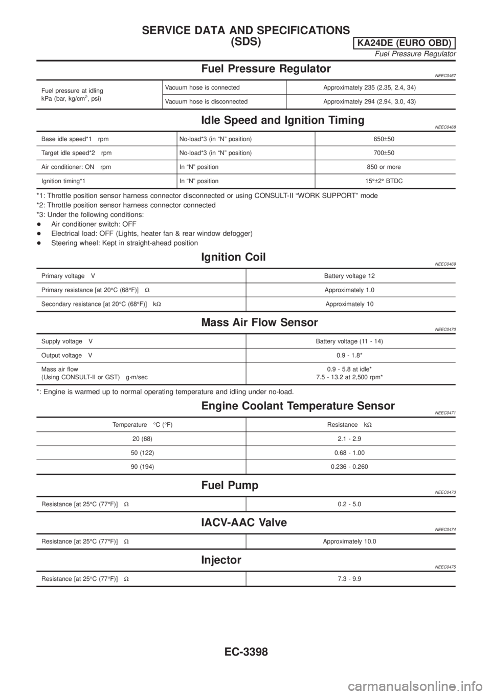
Fuel Pressure RegulatorNEEC0467
Fuel pressure at idling
kPa (bar, kg/cm2, psi)Vacuum hose is connected Approximately 235 (2.35, 2.4, 34)
Vacuum hose is disconnected Approximately 294 (2.94, 3.0, 43)
Idle Speed and Ignition TimingNEEC0468
Base idle speed*1 rpm No-load*3 (in ªNº position) 650±50
Target idle speed*2 rpm No-load*3 (in ªNº position) 700±50
Air conditioner: ON rpm In ªNº position 850 or more
Ignition timing*1 In ªNº position 15ɱ2É BTDC
*1: Throttle position sensor harness connector disconnected or using CONSULT-II ªWORK SUPPORTº mode
*2: Throttle position sensor harness connector connected
*3: Under the following conditions:
+Air conditioner switch: OFF
+Electrical load: OFF (Lights, heater fan & rear window defogger)
+Steering wheel: Kept in straight-ahead position
Ignition CoilNEEC0469
Primary voltage VBattery voltage 12
Primary resistance [at 20ÉC (68ÉF)]WApproximately 1.0
Secondary resistance [at 20ÉC (68ÉF)] kWApproximately 10
Mass Air Flow SensorNEEC0470
Supply voltage VBattery voltage (11 - 14)
Output voltage V0.9 - 1.8*
Mass air flow
(Using CONSULT-II or GST) g´m/sec0.9 - 5.8 at idle*
7.5 - 13.2 at 2,500 rpm*
*: Engine is warmed up to normal operating temperature and idling under no-load.
Engine Coolant Temperature SensorNEEC0471
Temperature ÉC (ÉF) Resistance kW
20 (68) 2.1 - 2.9
50 (122) 0.68 - 1.00
90 (194) 0.236 - 0.260
Fuel PumpNEEC0473
Resistance [at 25ÉC (77ÉF)]W0.2 - 5.0
IACV-AAC ValveNEEC0474
Resistance [at 25ÉC (77ÉF)]WApproximately 10.0
InjectorNEEC0475
Resistance [at 25ÉC (77ÉF)]W7.3 - 9.9
SERVICE DATA AND SPECIFICATIONS
(SDS)
KA24DE (EURO OBD)
Fuel Pressure Regulator
EC-3398
Page 425 of 1306
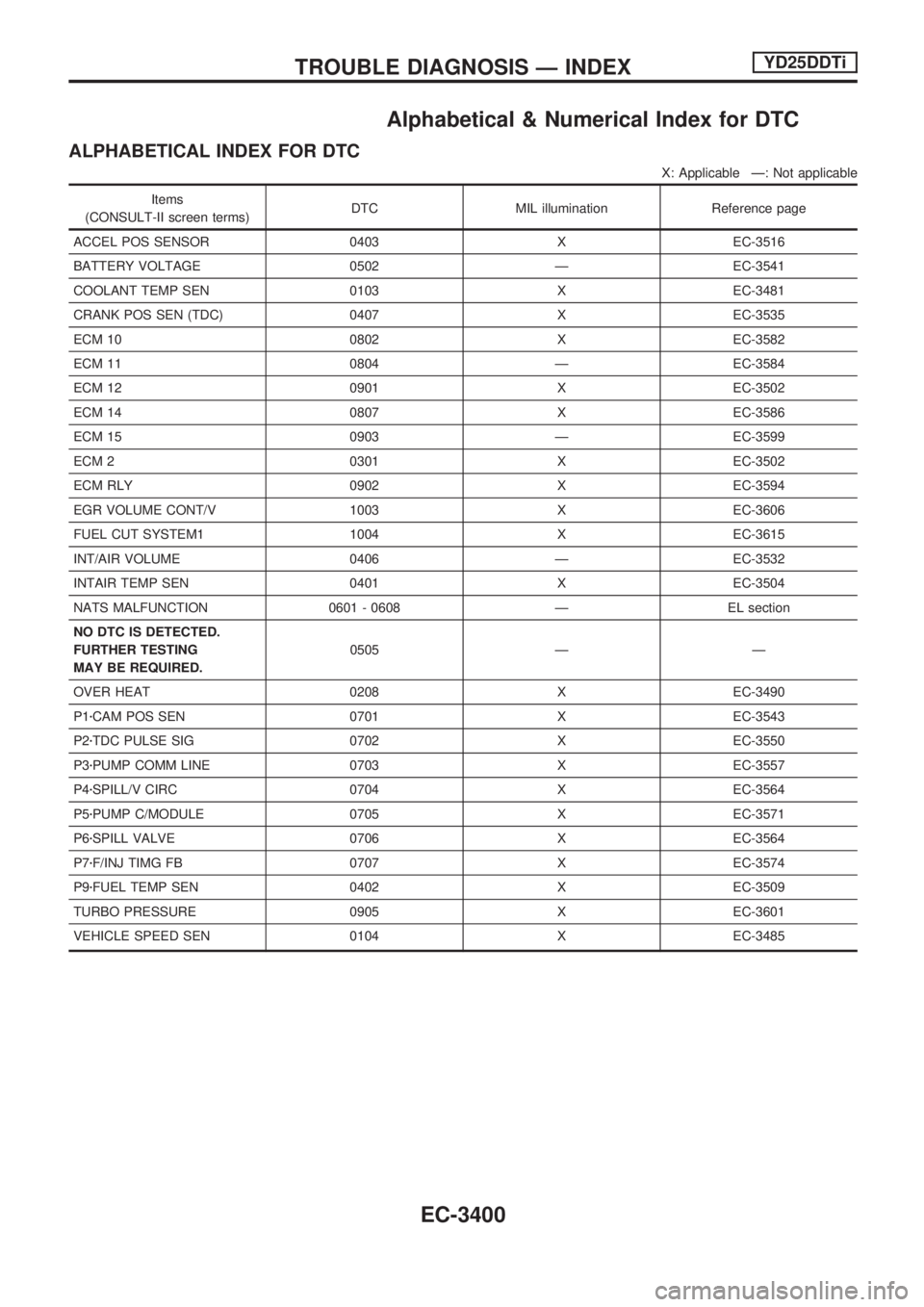
Alphabetical & Numerical Index for DTC
ALPHABETICAL INDEX FOR DTC
X: Applicable Ð: Not applicable
Items
(CONSULT-II screen terms)DTC MIL illumination Reference page
ACCEL POS SENSOR 0403 X EC-3516
BATTERY VOLTAGE 0502 Ð EC-3541
COOLANT TEMP SEN 0103 X EC-3481
CRANK POS SEN (TDC) 0407 X EC-3535
ECM 10 0802 X EC-3582
ECM 11 0804 Ð EC-3584
ECM 12 0901 X EC-3502
ECM 14 0807 X EC-3586
ECM 15 0903 Ð EC-3599
ECM 2 0301 X EC-3502
ECM RLY 0902 X EC-3594
EGR VOLUME CONT/V 1003 X EC-3606
FUEL CUT SYSTEM1 1004 X EC-3615
INT/AIR VOLUME 0406 Ð EC-3532
INTAIR TEMP SEN 0401 X EC-3504
NATS MALFUNCTION 0601 - 0608 Ð EL section
NO DTC IS DETECTED.
FURTHER TESTING
MAY BE REQUIRED.0505 Ð Ð
OVER HEAT 0208 X EC-3490
P1zCAM POS SEN 0701 X EC-3543
P2zTDC PULSE SIG 0702 X EC-3550
P3zPUMP COMM LINE 0703 X EC-3557
P4zSPILL/V CIRC 0704 X EC-3564
P5zPUMP C/MODULE 0705 X EC-3571
P6zSPILL VALVE 0706 X EC-3564
P7zF/INJ TIMG FB 0707 X EC-3574
P9zFUEL TEMP SEN 0402 X EC-3509
TURBO PRESSURE 0905 X EC-3601
VEHICLE SPEED SEN 0104 X EC-3485
TROUBLE DIAGNOSIS Ð INDEXYD25DDTi
EC-3400
Page 426 of 1306
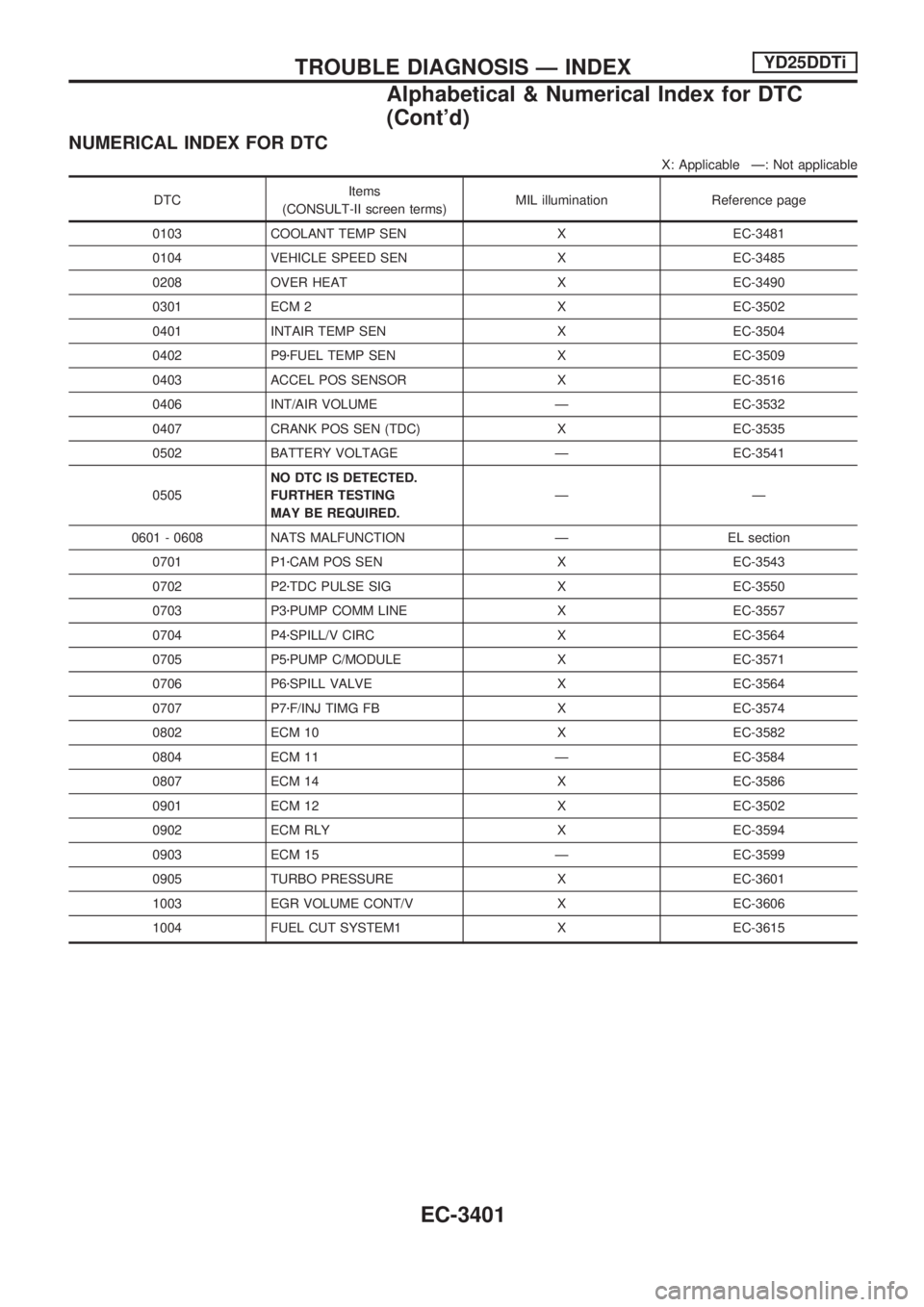
NUMERICAL INDEX FOR DTC
X: Applicable Ð: Not applicable
DTCItems
(CONSULT-II screen terms)MIL illumination Reference page
0103 COOLANT TEMP SEN X EC-3481
0104 VEHICLE SPEED SEN X EC-3485
0208 OVER HEAT X EC-3490
0301 ECM 2 X EC-3502
0401 INTAIR TEMP SEN X EC-3504
0402 P9zFUEL TEMP SEN X EC-3509
0403 ACCEL POS SENSOR X EC-3516
0406 INT/AIR VOLUME Ð EC-3532
0407 CRANK POS SEN (TDC) X EC-3535
0502 BATTERY VOLTAGE Ð EC-3541
0505NO DTC IS DETECTED.
FURTHER TESTING
MAY BE REQUIRED.ÐÐ
0601 - 0608 NATS MALFUNCTION Ð EL section
0701 P1zCAM POS SEN X EC-3543
0702 P2zTDC PULSE SIG X EC-3550
0703 P3zPUMP COMM LINE X EC-3557
0704 P4zSPILL/V CIRC X EC-3564
0705 P5zPUMP C/MODULE X EC-3571
0706 P6zSPILL VALVE X EC-3564
0707 P7zF/INJ TIMG FB X EC-3574
0802 ECM 10 X EC-3582
0804 ECM 11 Ð EC-3584
0807 ECM 14 X EC-3586
0901 ECM 12 X EC-3502
0902 ECM RLY X EC-3594
0903 ECM 15 Ð EC-3599
0905 TURBO PRESSURE X EC-3601
1003 EGR VOLUME CONT/V X EC-3606
1004 FUEL CUT SYSTEM1 X EC-3615
TROUBLE DIAGNOSIS Ð INDEXYD25DDTi
Alphabetical & Numerical Index for DTC
(Cont'd)
EC-3401
Page 435 of 1306
System Chart
Input (Sensor) ECM Function Output (Actuator)
+Electronic control fuel injection pump
+Crankshaft position sensor (TDC)
+Engine coolant temperature sensor
+Accelerator position sensor
+Accelerator position switch
+Park/Neutral position (PNP) switch
+Ignition switch
+Battery voltage
+Vehicle speed sensor
+Air conditioner switch
+Stop lamp switch
+Charge air pressure sensor
+Intake air temperature sensorFuel injection control Electronic control fuel injection pump
Fuel injection timing control Electronic control fuel injection pump
Fuel cut control Electronic control fuel injection pump
Glow control system Glow relay & glow lamp
On board diagnostic system MIL (On the instrument panel)
EGR volume control EGR volume control valve
Cooling fan control Cooling fan relay
Air conditioning cut control Air conditioner relay
ENGINE AND EMISSION CONTROL OVERALL SYSTEMYD25DDTi
EC-3410