Page 663 of 1306
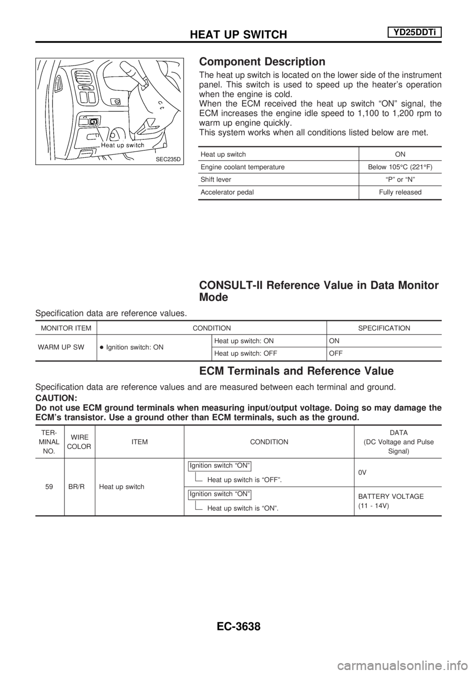
Component Description
The heat up switch is located on the lower side of the instrument
panel. This switch is used to speed up the heater's operation
when the engine is cold.
When the ECM received the heat up switch ªONº signal, the
ECM increases the engine idle speed to 1,100 to 1,200 rpm to
warm up engine quickly.
This system works when all conditions listed below are met.
Heat up switch ON
Engine coolant temperature Below 105ÉC (221ÉF)
Shift lever ªPº or ªNº
Accelerator pedal Fully released
CONSULT-II Reference Value in Data Monitor
Mode
Specification data are reference values.
MONITOR ITEM CONDITION SPECIFICATION
WARM UP SW+Ignition switch: ONHeat up switch: ON ON
Heat up switch: OFF OFF
ECM Terminals and Reference Value
Specification data are reference values and are measured between each terminal and ground.
CAUTION:
Do not use ECM ground terminals when measuring input/output voltage. Doing so may damage the
ECM's transistor. Use a ground other than ECM terminals, such as the ground.
TER-
MINAL
NO.WIRE
COLORITEM CONDITIONDATA
(DC Voltage and Pulse
Signal)
59 BR/R Heat up switchIgnition switch ªONº
Heat up switch is ªOFFº.0V
Ignition switch ªONº
Heat up switch is ªONº.BATTERY VOLTAGE
(11 - 14V)
SEC235D
HEAT UP SWITCHYD25DDTi
EC-3638
Page 675 of 1306
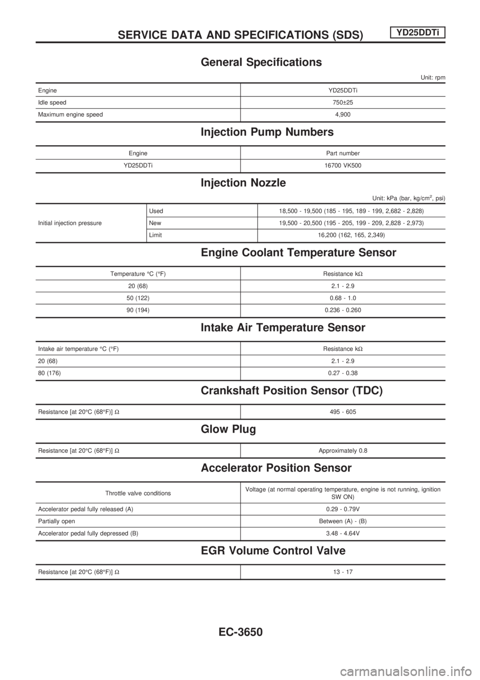
General Specifications
Unit: rpm
EngineYD25DDTi
Idle speed750 25
Maximum engine speed4,900
Injection Pump Numbers
Engine Part number
YD25DDTi 16700 VK500
Injection Nozzle
Unit: kPa (bar, kg/cm2, psi)
Initial injection pressureUsed 18,500 - 19,500 (185 - 195, 189 - 199, 2,682 - 2,828)
New 19,500 - 20,500 (195 - 205, 199 - 209, 2,828 - 2,973)
Limit 16,200 (162, 165, 2,349)
Engine Coolant Temperature Sensor
Temperature ÉC (ÉF) Resistance kW
20 (68) 2.1 - 2.9
50 (122) 0.68 - 1.0
90 (194) 0.236 - 0.260
Intake Air Temperature Sensor
Intake air temperature ÉC (ÉF)Resistance kW
20 (68)2.1 - 2.9
80 (176)0.27 - 0.38
Crankshaft Position Sensor (TDC)
Resistance [at 20ÉC (68ÉF)]W495 - 605
Glow Plug
Resistance [at 20ÉC (68ÉF)]WApproximately 0.8
Accelerator Position Sensor
Throttle valve conditionsVoltage (at normal operating temperature, engine is not running, ignition
SW ON)
Accelerator pedal fully released (A) 0.29 - 0.79V
Partially openBetween (A) - (B)
Accelerator pedal fully depressed (B) 3.48 - 4.64V
EGR Volume Control Valve
Resistance [at 20ÉC (68ÉF)]W13-17
SERVICE DATA AND SPECIFICATIONS (SDS)YD25DDTi
EC-3650
Page 702 of 1306
Bulb Replacement
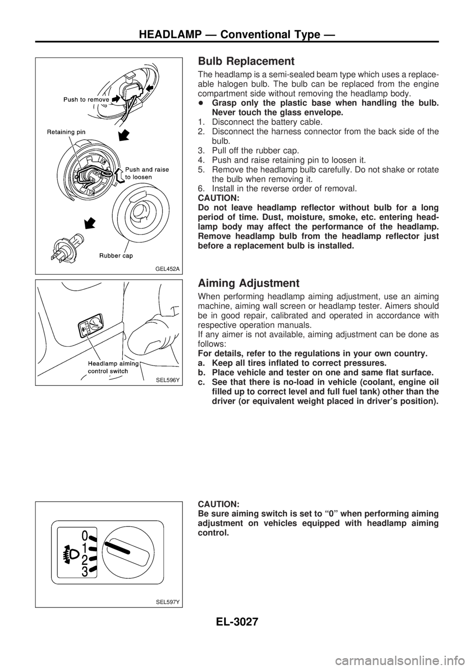
The headlamp is a semi-sealed beam type which uses a replace-
able halogen bulb. The bulb can be replaced from the engine
compartment side without removing the headlamp body.
+Grasp only the plastic base when handling the bulb.
Never touch the glass envelope.
1. Disconnect the battery cable.
2. Disconnect the harness connector from the back side of the
bulb.
3. Pull off the rubber cap.
4. Push and raise retaining pin to loosen it.
5. Remove the headlamp bulb carefully. Do not shake or rotate
the bulb when removing it.
6. Install in the reverse order of removal.
CAUTION:
Do not leave headlamp reflector without bulb for a long
period of time. Dust, moisture, smoke, etc. entering head-
lamp body may affect the performance of the headlamp.
Remove headlamp bulb from the headlamp reflector just
before a replacement bulb is installed.
Aiming Adjustment
When performing headlamp aiming adjustment, use an aiming
machine, aiming wall screen or headlamp tester. Aimers should
be in good repair, calibrated and operated in accordance with
respective operation manuals.
If any aimer is not available, aiming adjustment can be done as
follows:
For details, refer to the regulations in your own country.
a. Keep all tires inflated to correct pressures.
b. Place vehicle and tester on one and same flat surface.
c. See that there is no-load in vehicle (coolant, engine oil
filled up to correct level and full fuel tank) other than the
driver (or equivalent weight placed in driver's position).
CAUTION:
Be sure aiming switch is set to ª0º when performing aiming
adjustment on vehicles equipped with headlamp aiming
control.
GEL452A
SEL596Y
SEL597Y
HEADLAMP Ð Conventional Type Ð
EL-3027
Page 869 of 1306
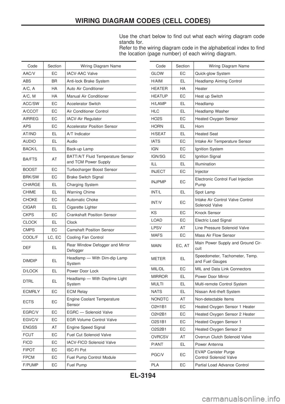
Use the chart below to find out what each wiring diagram code
stands for.
Refer to the wiring diagram code in the alphabetical index to find
the location (page number) of each wiring diagram.
Code Section Wiring Diagram Name
AAC/V EC IACV-AAC Valve
ABS BR Anti-lock Brake System
A/C, A HA Auto Air Conditioner
A/C, M HA Manual Air Conditioner
ACC/SW EC Accelerator Switch
A/CCOT EC Air Conditioner Control
AIRREG EC IACV-Air Regulator
APS EC Accelerator Position Sensor
AT/IND EL A/T Indicator
AUDIO EL Audio
BACK/L EL Back-up Lamp
BA/FTS ATBATT/A/T Fluid Temperature Sensor
and TCM Power Supply
BOOST EC Turbocharger Boost Sensor
BRK/SW EC Brake Switch Signal
CHARGE EL Charging System
CHIME EL Warning Chime
CHOKE EC Automatic Choke
CIGAR EL Cigarette Lighter
CKPS EC Crankshaft Position Sensor
CLOCK EL Clock
CMPS EC Camshaft Position Sensor
COOL/F LC, EC Cooling Fan Control
DEF ELRear Window Defogger and Mirror
Defogger
DIMDIP ELHeadlamp Ð With Dim-dip Lamp
System
D/LOCK EL Power Door Lock
DTRL ELHeadlamp Ð With Daytime Light
System
ECMRLY EC ECM Relay
ECTS ECEngine Coolant Temperature
Sensor
EGRC/V EC EGRC Ð Solenoid Valve
EGVC/V EC EGR Volume Control Valve
ENGSS AT Engine Speed Signal
FCUT EC Fuel Cut Solenoid Valve
FICD EC IACV-FICD Solenoid Valve
FIPOT EC ISC-FI Pot
FPCM EC Fuel Pump Control Module
F/PUMP EC Fuel PumpCode Section Wiring Diagram Name
GLOW EC Quick-glow System
H/AIM EL Headlamp Aiming Control
HEATER HA Heater
HEATUP EC Heat up Switch
H/LAMP EL Headlamp
HLC EL Headlamp Washer
HO2S EC Heated Oxygen Sensor
HORN EL Horn
H/SEAT EL Heated Seat
IATS EC Intake Air Temperature Sensor
IGN EC Ignition System
IGN/SG EC Ignition Signal
ILL EL Illumination
INJECT EC Injector
INJPMP ECElectronic Control Fuel Injection
Pump
INT/L EL Spot Lamp
INT/V ECIntake Air Control Valve Control
Solenoid Valve
KS EC Knock Sensor
LOAD EC Electric Load Signal
LPSV AT Line Pressure Solenoid Valve
MAFS EC Mass Air Flow Sensor
MAIN EC, ATMain Power Supply and Ground Cir-
cuit
METER ELSpeedometer, Tachometer, Temp.
and Fuel Gauges
MIL/DL EC MIL and Data Link Connectors
MIRROR EL Power Door Mirror
MULTI EL Multi-remote Control System
NATS EL Nissan Anti-theft System
NONDTC AT Non-detectable Items
O2H1B1 EC Heated Oxygen Sensor 1 Heater
O2H2B1 EC Heated Oxygen Sensor 2 Heater
O2S1B1 EC Heated Oxygen Sensor 1
O2S2B1 EC Heated Oxygen Sensor 2
OVRCSV AT Overrun Clutch Solenoid Valve
P/ANT EL Power Antenna
PGC/V ECEVAP Canister Purge
Control Solenoid Valve
PLA EC Partial Load Advance Control
WIRING DIAGRAM CODES (CELL CODES)
EL-3194
Page 880 of 1306
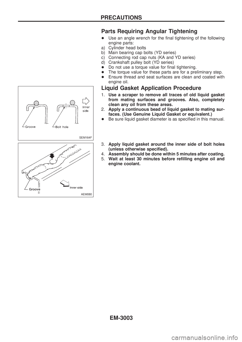
Parts Requiring Angular Tightening
+Use an angle wrench for the final tightening of the following
engine parts:
a) Cylinder head bolts
b) Main bearing cap bolts (YD series)
c) Connecting rod cap nuts (KA and YD series)
d) Crankshaft pulley bolt (YD series)
+Do not use a torque value for final tightening.
+The torque value for these parts are for a preliminary step.
+Ensure thread and seat surfaces are clean and coated with
engine oil.
Liquid Gasket Application Procedure
1.Use a scraper to remove all traces of old liquid gasket
from mating surfaces and grooves. Also, completely
clean any oil from these areas.
2.Apply a continuous bead of liquid gasket to mating sur-
faces. (Use Genuine Liquid Gasket or equivalent.)
+Be sure liquid gasket diameter is as specified in this manual.
3.Apply liquid gasket around the inner side of bolt holes
(unless otherwise specified).
4.Assembly should be done within 5 minutes after coating.
5.Wait at least 30 minutes before refilling engine oil and
engine coolant.
SEM164F
AEM080
PRECAUTIONS
EM-3003
Page 898 of 1306
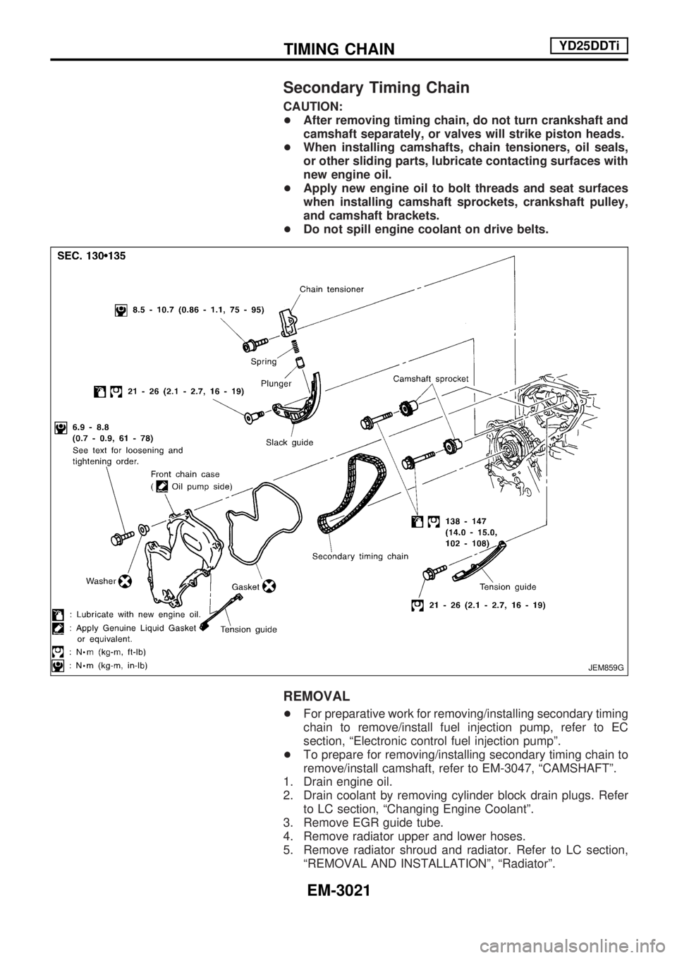
Secondary Timing Chain
CAUTION:
+After removing timing chain, do not turn crankshaft and
camshaft separately, or valves will strike piston heads.
+When installing camshafts, chain tensioners, oil seals,
or other sliding parts, lubricate contacting surfaces with
new engine oil.
+Apply new engine oil to bolt threads and seat surfaces
when installing camshaft sprockets, crankshaft pulley,
and camshaft brackets.
+Do not spill engine coolant on drive belts.
REMOVAL
+For preparative work for removing/installing secondary timing
chain to remove/install fuel injection pump, refer to EC
section, ªElectronic control fuel injection pumpº.
+To prepare for removing/installing secondary timing chain to
remove/install camshaft, refer to EM-3047, ªCAMSHAFTº.
1. Drain engine oil.
2. Drain coolant by removing cylinder block drain plugs. Refer
to LC section, ªChanging Engine Coolantº.
3. Remove EGR guide tube.
4. Remove radiator upper and lower hoses.
5. Remove radiator shroud and radiator. Refer to LC section,
ªREMOVAL AND INSTALLATIONº, ªRadiatorº.
JEM859G
TIMING CHAINYD25DDTi
EM-3021
Page 904 of 1306
CAUTION:
+After removing timing chain, do not turn crankshaft and
camshaft separately, or valves will strike piston heads.
+When installing camshafts, chain tensioners, oil seals,
or other sliding parts, lubricate contacting surfaces with
new engine oil.
+Apply new engine oil to bolt threads and seat surfaces
when installing camshaft sprockets, crankshaft pulley,
and camshaft brackets.
+Do not spill engine coolant on drive belts.
REMOVAL
1. Remove charge air cooler and bracket.
2. Remove rocker cover. Refer to EM-3045, ªRemoval and
Installationº, ªROCKER COVERº.
3. Remove EGR guide tube.
4. Remove radiator shroud and radiator. Refer to LC section,
ªREMOVAL AND INSTALLATIONº, ªRadiatorº.
5. Remove idler pulley, idler pulley bracket and drive belts.
6. Remove upper and lower oil pans. Refer to EM-3015,
ªRemoval
and Installationº, ªOIL PANº.
7. Remove injection tube.
Refer to EC section, ªInjection Tube and Injection Nozzleº.
8. Remove secondary timing chain and associated parts.
Refer to EM-3021, ªSecondary Timing Chainº.
9. When removing rear chain case, remove camshaft sprock-
ets.
Refer to EM-3047, ªCAMSHAFTº.
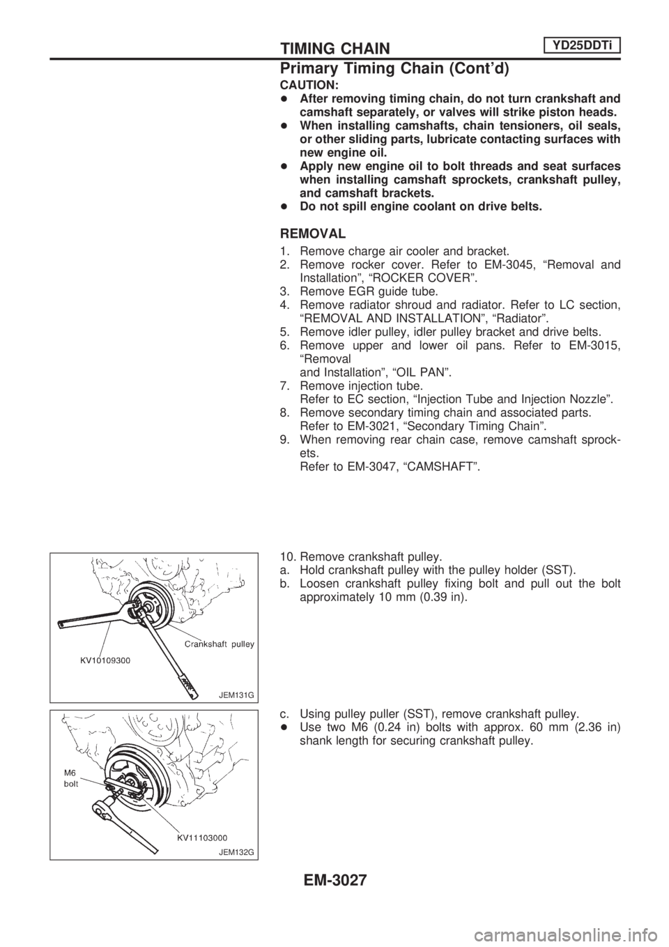
10. Remove crankshaft pulley.
a. Hold crankshaft pulley with the pulley holder (SST).
b. Loosen crankshaft pulley fixing bolt and pull out the bolt
approximately 10 mm (0.39 in).
c. Using pulley puller (SST), remove crankshaft pulley.
+Use two M6 (0.24 in) bolts with approx. 60 mm (2.36 in)
shank length for securing crankshaft pulley.
JEM131G
JEM132G
TIMING CHAINYD25DDTi
Primary Timing Chain (Cont'd)
EM-3027
Page 912 of 1306
Removal and Installation
1. Intake manifold
2. EGR guide tube
3. EGR volume control valve
4. EGR spacer5. EGR tube
6. Cylinder head
7. Cylinder block8. Injection tube clamp
9. Injection tube
10 Injection nozzle oil seal
REMOVAL
1. Drain engine coolant. Refer to LC section, ªChanging engine
coolantº.
2. Remove charge air cooler. Refer to EM-3014, ªRemoval and-
Installationº.
3. Remove EGR volume control valve, EGR spacer and EGR
guide tube.
4. Remove fuel injection tubes and intake manifold.
SEM866G
INTAKE MANIFOLDYD25DDTi
EM-3035