2001 NISSAN PICK-UP coolant
[x] Cancel search: coolantPage 924 of 1306
CAUTION:
+When installing camshafts, chain tensioners, oil seals,
or other sliding parts, lubricate contacting surfaces with
new engine oil.
+Apply new engine oil to threads and seat surfaces when
installing cylinder head, camshaft sprocket, crankshaft
pulley, and camshaft bracket.
+Attach tags to valve lifters so as not to mix them up.
Removal
1. Drain engine coolant. Refer to LC section, ªChanging Engine
Coolantº.
2. Remove exhaust manifold, Turbocharger. Refer to EM-3039,
ªRemoval and Installationº.
3. Remove intake manifold. Refer to EM-3035, ªRemoval and
Installationº.
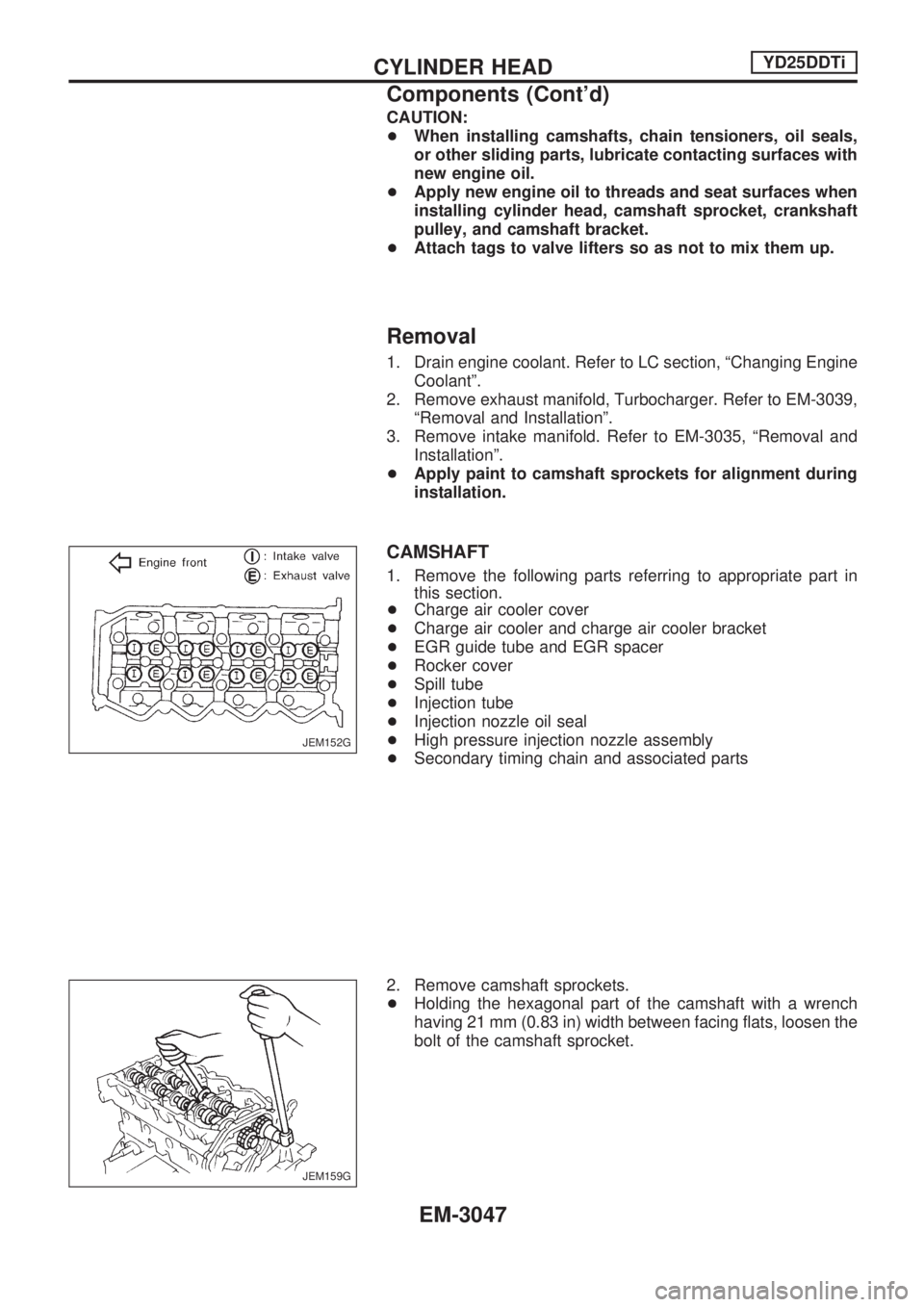
+Apply paint to camshaft sprockets for alignment during
installation.
CAMSHAFT
1. Remove the following parts referring to appropriate part in
this section.
+Charge air cooler cover
+Charge air cooler and charge air cooler bracket
+EGR guide tube and EGR spacer
+Rocker cover
+Spill tube
+Injection tube
+Injection nozzle oil seal
+High pressure injection nozzle assembly
+Secondary timing chain and associated parts
2. Remove camshaft sprockets.
+Holding the hexagonal part of the camshaft with a wrench
having 21 mm (0.83 in) width between facing flats, loosen the
bolt of the camshaft sprocket.
JEM152G
JEM159G
CYLINDER HEADYD25DDTi
Components (Cont'd)
EM-3047
Page 941 of 1306
Removal
Preparation
1. Drain coolant from radiator drain plugs.
2. Remove the following parts.
+Engine hood
+Charge air cooler
+Under protector
+Battery
+Radiator shroud
+Radiator
+Accessory belt
+Cooling fan
+Exhaust front tube
Engine room (Left)
3. Remove air duct and air cleaner case.
4. Disconnect harness connectors from alternator and air con-
ditioner compressor.
5. Remove alternator.
6. Remove installation bolts. Relocate air conditioner compres-
sor. Use a rope to temporarily anchor it to vehicle side.
7. Disconnect and relocate heating hose, install blank cap to
hose to prevent coolant from leaking.
8. Remove heat insulator.
Engine room (Right)
9. Remove fuel feed and return hoses.
CAUTION:
Install blank caps immediately to avoid fuel leakage.
10. Remove all harness connectors on the engine, and move
harnesses to the side of the vehicle.
Vehicle underfloor
11. Remove starter motor.
12. Remove front propeller shaft.
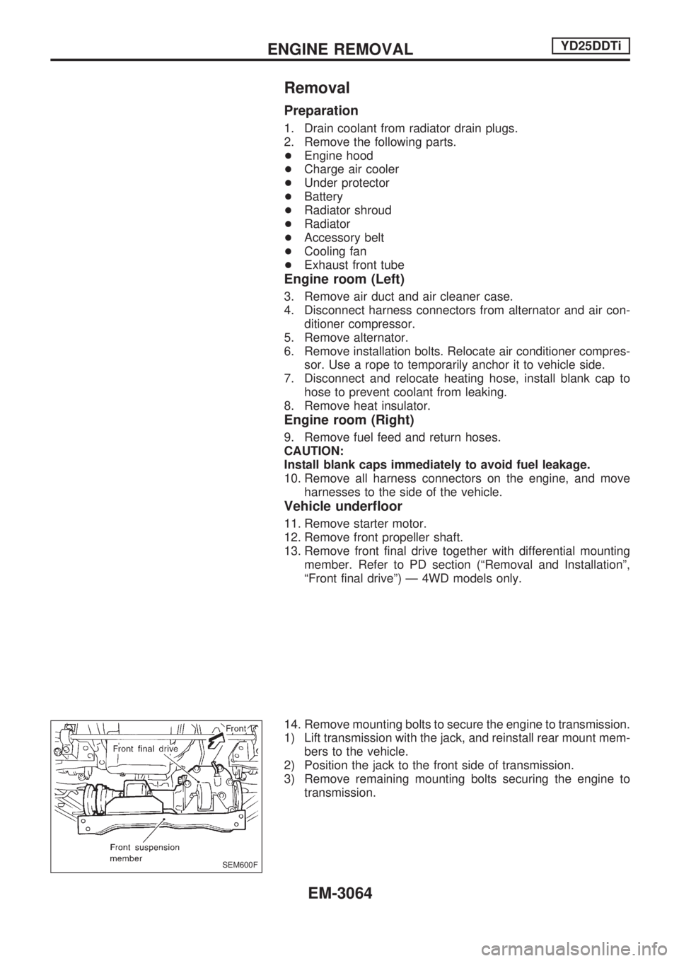
13. Remove front final drive together with differential mounting
member. Refer to PD section (ªRemoval and Installationº,
ªFront final driveº) Ð 4WD models only.
14. Remove mounting bolts to secure the engine to transmission.
1) Lift transmission with the jack, and reinstall rear mount mem-
bers to the vehicle.
2) Position the jack to the front side of transmission.
3) Remove remaining mounting bolts securing the engine to
transmission.
SEM600F
ENGINE REMOVALYD25DDTi
EM-3064
Page 942 of 1306
Removal operation
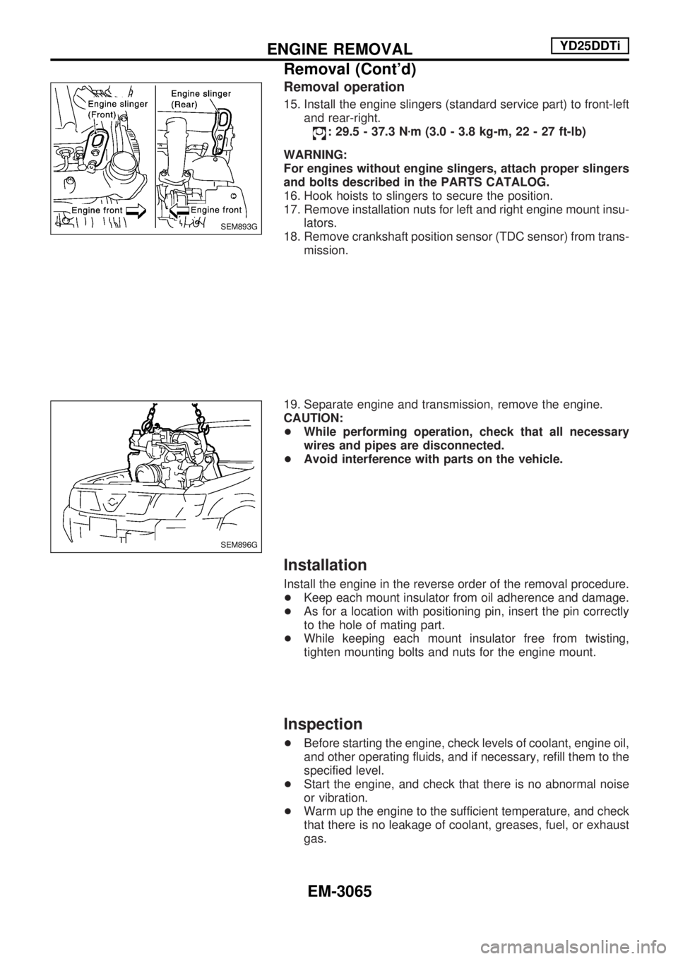
15. Install the engine slingers (standard service part) to front-left
and rear-right.
: 29.5 - 37.3 Nzm (3.0 - 3.8 kg-m, 22 - 27 ft-lb)
WARNING:
For engines without engine slingers, attach proper slingers
and bolts described in the PARTS CATALOG.
16. Hook hoists to slingers to secure the position.
17. Remove installation nuts for left and right engine mount insu-
lators.
18. Remove crankshaft position sensor (TDC sensor) from trans-
mission.
19. Separate engine and transmission, remove the engine.
CAUTION:
+While performing operation, check that all necessary
wires and pipes are disconnected.
+Avoid interference with parts on the vehicle.
Installation
Install the engine in the reverse order of the removal procedure.
+Keep each mount insulator from oil adherence and damage.
+As for a location with positioning pin, insert the pin correctly
to the hole of mating part.
+While keeping each mount insulator free from twisting,
tighten mounting bolts and nuts for the engine mount.
Inspection
+Before starting the engine, check levels of coolant, engine oil,
and other operating fluids, and if necessary, refill them to the
specified level.
+Start the engine, and check that there is no abnormal noise
or vibration.
+Warm up the engine to the sufficient temperature, and check
that there is no leakage of coolant, greases, fuel, or exhaust
gas.
SEM893G
SEM896G
ENGINE REMOVALYD25DDTi
Removal (Cont'd)
EM-3065
Page 945 of 1306
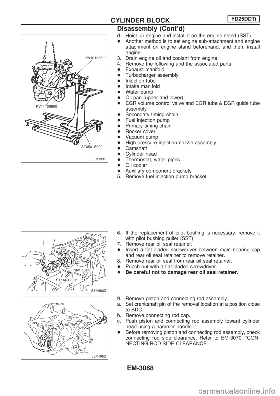
d. Hoist up engine and install it on the engine stand (SST).
+Another method is to set engine sub-attachment and engine
attachment on engine stand beforehand, and then, install
engine.
3. Drain engine oil and coolant from engine.
4. Remove the following and the associated parts:
+Exhaust manifold
+Turbocharger assembly
+Injection tube
+Intake manifold
+Water pump
+Oil pan (upper and lower)
+EGR volume control valve and EGR tube & EGR guide tube
assembly
+Secondary timing chain
+Fuel injection pump
+Primary timing chain
+Rocker cover
+Vacuum pump
+High pressure injection nozzle assembly
+Camshaft
+Cylinder head
+Thermostat, water pipes
+Oil cooler
+Auxiliary component brackets
5. Remove fuel injection pump bracket.
6. If the replacement of pilot bushing is necessary, remove it
with pilot bushing puller (SST).
7. Remove rear oil seal retainer.
+Insert a flat-bladed screwdriver between main bearing cap
and rear oil seal retainer to remove retainer.
8. Remove rear oil seal from rear oil seal retainer.
+Punch out with a flat-bladed screwdriver.
+Be careful not to damage rear oil seal retainer.
9. Remove piston and connecting rod assembly.
a. Set crankshaft pin of the removal location at a position close
to BDC.
b. Remove connecting rod cap.
c. Push piston and connecting rod assembly toward cylinder
head using a hammer handle.
+Before removing piston and connecting rod assembly, check
connecting rod side clearance. Refer to EM-3070, ªCON-
NECTING ROD SIDE CLEARANCEº.
JEM193G
SEM500G
JEM195G
CYLINDER BLOCKYD25DDTi
Disassembly (Cont'd)
EM-3068
Page 959 of 1306

CRANKSHAFT
1. Blow air sufficiently into the coolant passage, oil passage in
the cylinder block, inside of crankshaft case, and inside of
cylinder bores to remove any foreign materials.
2. Install oil jet relief valves.
3. Install oil jets.
4. Install main bearings and thrust bearings.
a. Remove debris, dust, and oil from the locations on the cylin-
der block and main bearing caps where bearings are
installed.
b. Install thrust bearing on each side of cylinder block No. 3
housing.
+Install thrust bearings with oil groove facing in the direction
of the crankshaft arm (outside).
c. Be sure to install main bearings in the correct direction.
+Make sure those with oil holes or oil grooves are mounted on
the cylinder block side, and those without oil holes or oil
grooves are on the main cap side.
+Before installing, apply engine oil on the front (inner) surfaces
of bearings. Do not apply oil to the back surfaces, but thor-
oughly clean them.
+Align stopper notches on bearings and install.
+Check the oil holes on cylinder block and those on bearings
are aligned.
5. Install crankshaft to cylinder block.
+Make sure crankshaft rotates smoothly by hand.
6. Install main bearing caps.
+Identify main bearing caps by the punched mark. Install
correctly, matching the journal No. on the bearing cap and
the journal, with the front mark facing forward.
+Main bearing caps are commonly processed with the cylin-
der block. Therefore, caps and cylinder block should be
replaced as a set.
JEM223G
JEM224G
JEM213G
JEM225G
CYLINDER BLOCKYD25DDTi
Assembly (Cont'd)
EM-3082
Page 1023 of 1306
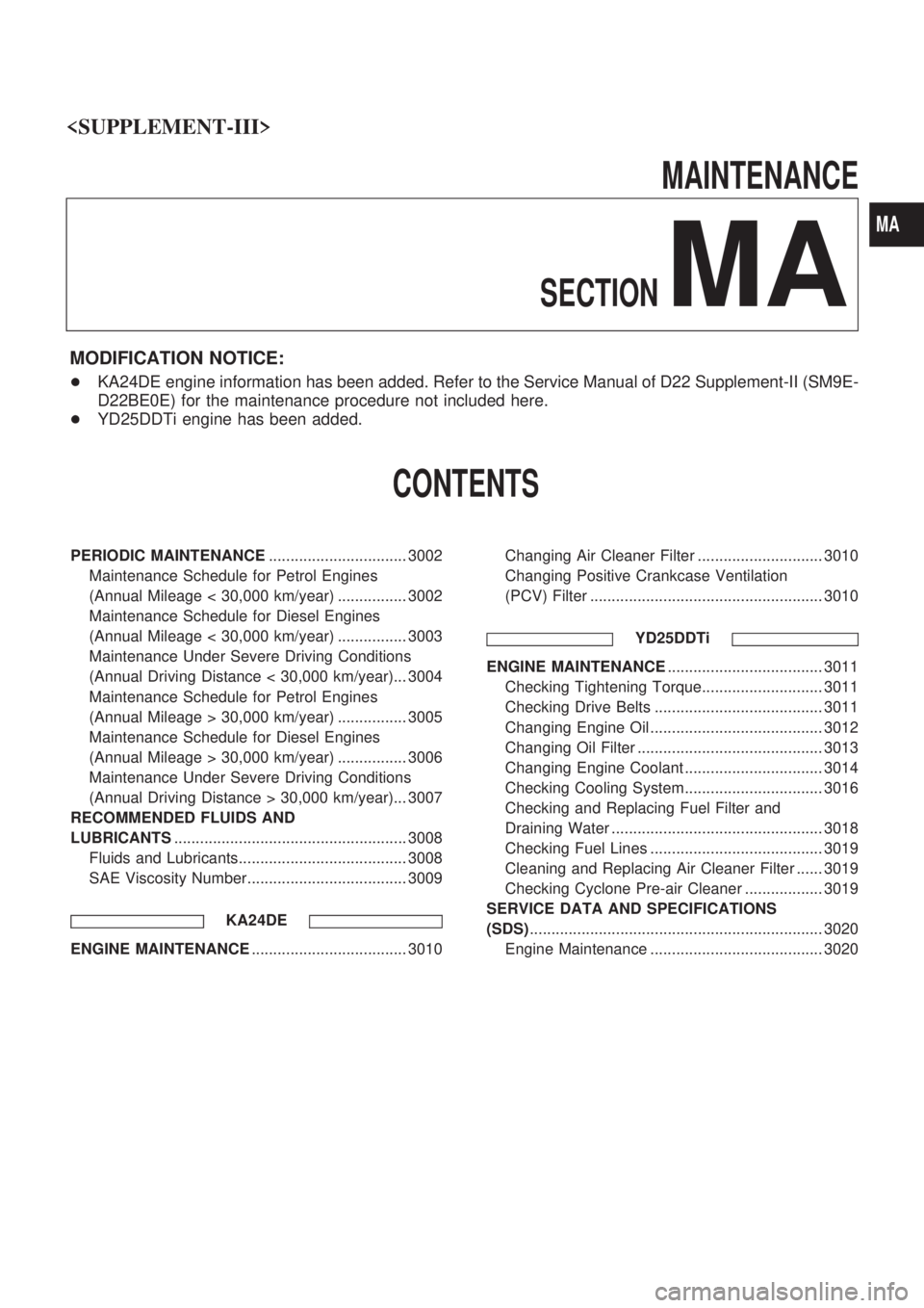
MAINTENANCE
SECTION
MA
MODIFICATION NOTICE:
+KA24DE engine information has been added. Refer to the Service Manual of D22 Supplement-II (SM9E-
D22BE0E) for the maintenance procedure not included here.
+YD25DDTi engine has been added.
CONTENTS
PERIODIC MAINTENANCE................................ 3002
Maintenance Schedule for Petrol Engines
(Annual Mileage < 30,000 km/year) ................ 3002
Maintenance Schedule for Diesel Engines
(Annual Mileage < 30,000 km/year) ................ 3003
Maintenance Under Severe Driving Conditions
(Annual Driving Distance < 30,000 km/year)... 3004
Maintenance Schedule for Petrol Engines
(Annual Mileage > 30,000 km/year) ................ 3005
Maintenance Schedule for Diesel Engines
(Annual Mileage > 30,000 km/year) ................ 3006
Maintenance Under Severe Driving Conditions
(Annual Driving Distance > 30,000 km/year)... 3007
RECOMMENDED FLUIDS AND
LUBRICANTS...................................................... 3008
Fluids and Lubricants....................................... 3008
SAE Viscosity Number..................................... 3009
KA24DE
ENGINE MAINTENANCE.................................... 3010Changing Air Cleaner Filter ............................. 3010
Changing Positive Crankcase Ventilation
(PCV) Filter ...................................................... 3010
YD25DDTi
ENGINE MAINTENANCE.................................... 3011
Checking Tightening Torque............................ 3011
Checking Drive Belts ....................................... 3011
Changing Engine Oil ........................................ 3012
Changing Oil Filter ........................................... 3013
Changing Engine Coolant ................................ 3014
Checking Cooling System................................ 3016
Checking and Replacing Fuel Filter and
Draining Water ................................................. 3018
Checking Fuel Lines ........................................ 3019
Cleaning and Replacing Air Cleaner Filter ...... 3019
Checking Cyclone Pre-air Cleaner .................. 3019
SERVICE DATA AND SPECIFICATIONS
(SDS).................................................................... 3020
Engine Maintenance ........................................ 3020
MA
Page 1024 of 1306
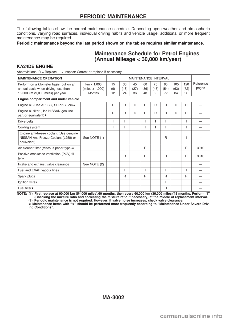
The following tables show the normal maintenance schedule. Depending upon weather and atmospheric
conditions, varying road surfaces, individual driving habits and vehicle usage, additional or more frequent
maintenance may be required.
Periodic maintenance beyond the last period shown on the tables requires similar maintenance.
Maintenance Schedule for Petrol Engines
(Annual Mileage < 30,000 km/year)
KA24DE ENGINE
Abbreviations: R = Replace I = Inspect: Correct or replace if necessary
MAINTENANCE OPERATIONMAINTENANCE INTERVAL
Reference
pages Perform on a kilometer basis, but on an
annual basis when driving less than
15,000 km (9,000 miles) per yearkm x 1,000
(miles x 1,000)
Months15
(9)
1230
(18)
2445
(27)
3660
(36)
4875
(45)
6090
(54)
72105
(63)
84120
(72)
96
Engine compartment and under vehicle
Engine oil (Use API SG, SH or SJ oil)HR RRRRRRR Ð
Engine oil filter (Use NISSAN genuine
part or equivalent)HR RRRRRRR Ð
Drive belts IIIIIIII Ð
Cooling system IIIIIIII Ð
Engine anti-freeze coolant (Use genuine
NISSAN Anti-Freeze Coolant (L250) or
equivalent)See NOTE (1) I R I Ð
Air cleaner filter (Viscous paper type)HR R 3010
Positive crankcase ventilation (PCV) fil-
terHRRRR3010
Intake and exhaust valve clearance See NOTE (2) Ð
Fuel and EVAP vapour linesIIIIÐ
Spark plugsRRRRÐ
Ignition wires I I Ð
Fuel filterHRÐ
NOTE: (1) First replace at 90,000 km (54,000 miles)/60 months, then every 60,000 km (36,000 miles)/48 months. Perform ªIº
(Checking the mixture ratio and correcting the mixture ratio if necessary) at the middle of replacement interval.
(2) Periodic maintenance is not required. However, if valve noise increases, check valve clearance.
HMaintenance items with ªHº should be performed more frequently according to ªMaintenance Under Severe Driv-
ing Conditionsº.
PERIODIC MAINTENANCE
MA-3002
Page 1025 of 1306
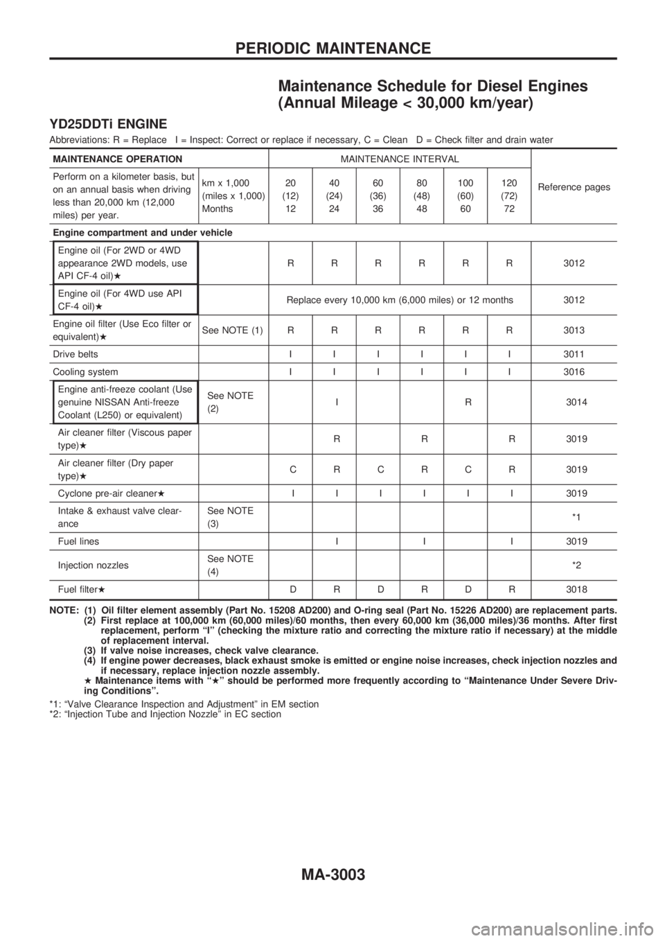
Maintenance Schedule for Diesel Engines
(Annual Mileage < 30,000 km/year)
YD25DDTi ENGINE
Abbreviations: R = Replace I = Inspect: Correct or replace if necessary, C = Clean D = Check filter and drain water
MAINTENANCE OPERATIONMAINTENANCE INTERVAL
Reference pages Perform on a kilometer basis, but
on an annual basis when driving
less than 20,000 km (12,000
miles) per year.km x 1,000
(miles x 1,000)
Months20
(12)
1240
(24)
2460
(36)
3680
(48)
48100
(60)
60120
(72)
72
Engine compartment and under vehicle
Engine oil (For 2WD or 4WD
appearance 2WD models, use
API CF-4 oil)HRRRRRR3012
Engine oil (For 4WD use API
CF-4 oil)HReplace every 10,000 km (6,000 miles) or 12 months 3012
Engine oil filter (Use Eco filter or
equivalent)HSee NOTE (1)RRRRRR3013
Drive beltsIIIIII3011
Cooling systemIIIIII3016
Engine anti-freeze coolant (Use
genuine NISSAN Anti-freeze
Coolant (L250) or equivalent)See NOTE
(2)I R 3014
Air cleaner filter (Viscous paper
type)HR R R 3019
Air cleaner filter (Dry paper
type)HCRCRCR3019
Cyclone pre-air cleanerHIIIIII3019
Intake & exhaust valve clear-
anceSee NOTE
(3)*1
Fuel lines I I I 3019
Injection nozzlesSee NOTE
(4)*2
Fuel filterHDRDRDR3018
NOTE: (1) Oil filter element assembly (Part No. 15208 AD200) and O-ring seal (Part No. 15226 AD200) are replacement parts.
(2) First replace at 100,000 km (60,000 miles)/60 months, then every 60,000 km (36,000 miles)/36 months. After first
replacement, perform ªIº (checking the mixture ratio and correcting the mixture ratio if necessary) at the middle
of replacement interval.
(3) If valve noise increases, check valve clearance.
(4) If engine power decreases, black exhaust smoke is emitted or engine noise increases, check injection nozzles and
if necessary, replace injection nozzle assembly.
HMaintenance items with ªHº should be performed more frequently according to ªMaintenance Under Severe Driv-
ing Conditionsº.
*1: ªValve Clearance Inspection and Adjustmentº in EM section
*2: ªInjection Tube and Injection Nozzleº in EC section
PERIODIC MAINTENANCE
MA-3003