Page 372 of 1306
4 CHECK ENGINE COOLANT TEMPERATURE SENSOR
Check resistance as shown in the figure.
SEF152P
MTBL0285
SEF012P
OK or NG
OK©GO TO 5.
NG©Replace engine coolant temperature sensor.
5 CHECK MAIN 11 CAUSES
If the cause cannot be isolated, go to ªMAIN 11 CAUSES OF OVERHEATINGº, EC-3348.
©INSPECTION END
Perform FINAL CHECK by the following procedure after repair
is completed.
1. Warm up engine. Run the vehicle for at least 20 minutes. Pay
attention to engine coolant temperature gauge on the instru-
ment panel. If the reading shows an abnormally high
temperature, another part may be malfunctioning.
2. Stop vehicle and let engine idle. Check the intake and exhaust
systems for leaks by listening for noise or visually inspecting
the components.
3. Allow engine to cool and visually check for oil and coolant
leaks. Then, perform ªOVERALL FUNCTION CHECKº.
DTC P1217 ENGINE OVER
TEMPERATURE
KA24DE (EURO OBD)
Diagnostic Procedure
EC-3347
Page 373 of 1306
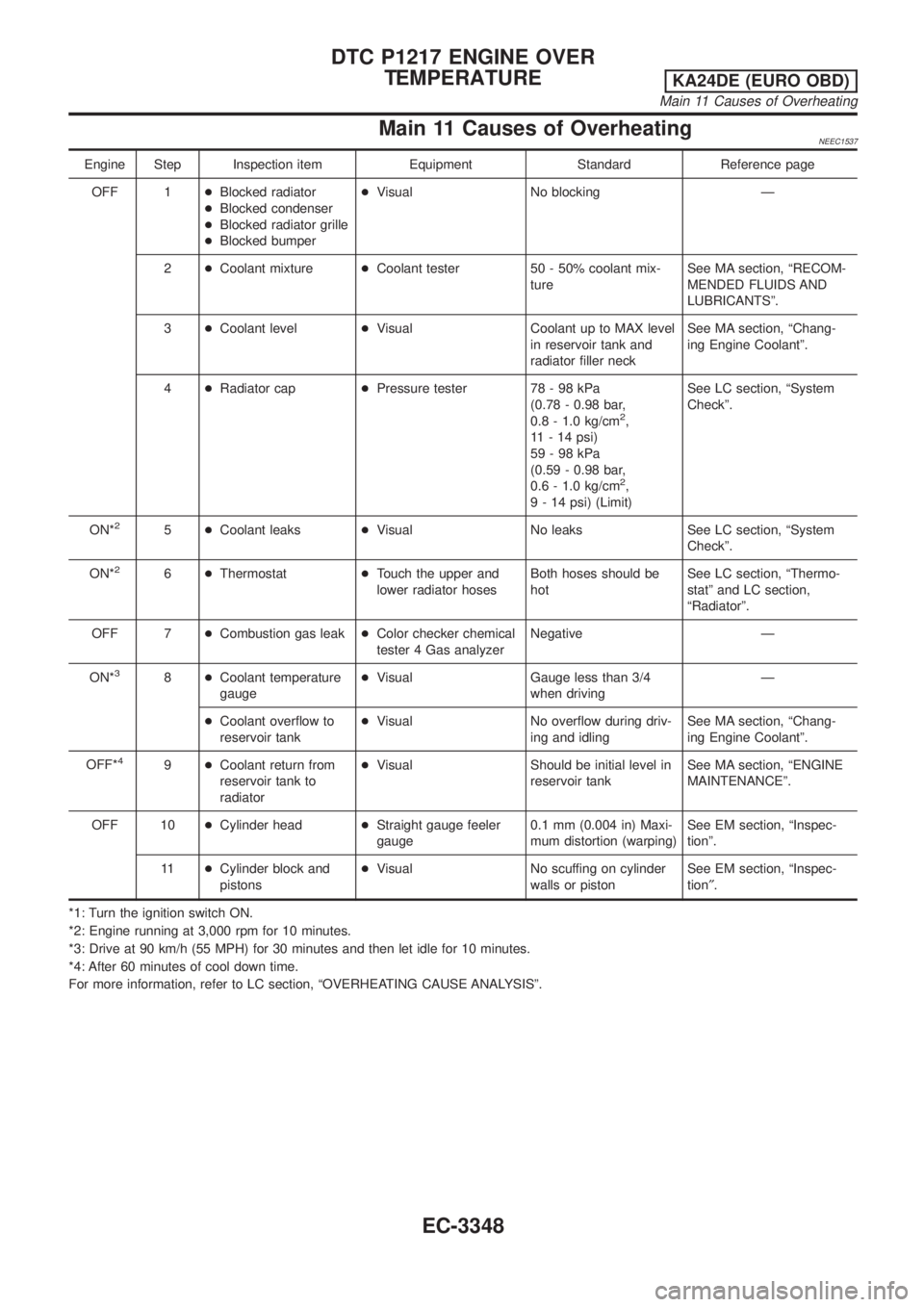
Main 11 Causes of OverheatingNEEC1537
Engine Step Inspection item Equipment Standard Reference page
OFF 1+Blocked radiator
+Blocked condenser
+Blocked radiator grille
+Blocked bumper+Visual No blocking Ð
2+Coolant mixture+Coolant tester 50 - 50% coolant mix-
tureSee MA section, ªRECOM-
MENDED FLUIDS AND
LUBRICANTSº.
3+Coolant level+Visual Coolant up to MAX level
in reservoir tank and
radiator filler neckSee MA section, ªChang-
ing Engine Coolantº.
4+Radiator cap+Pressure tester 78 - 98 kPa
(0.78 - 0.98 bar,
0.8 - 1.0 kg/cm
2,
11 - 14 psi)
59-98kPa
(0.59 - 0.98 bar,
0.6 - 1.0 kg/cm
2,
9 - 14 psi) (Limit)See LC section, ªSystem
Checkº.
ON*
25+Coolant leaks+Visual No leaks See LC section, ªSystem
Checkº.
ON*
26+Thermostat+Touch the upper and
lower radiator hosesBoth hoses should be
hotSee LC section, ªThermo-
statº and LC section,
ªRadiatorº.
OFF 7+Combustion gas leak+Color checker chemical
tester 4 Gas analyzerNegative Ð
ON*
38+Coolant temperature
gauge+Visual Gauge less than 3/4
when drivingÐ
+Coolant overflow to
reservoir tank+Visual No overflow during driv-
ing and idlingSee MA section, ªChang-
ing Engine Coolantº.
OFF*
49+Coolant return from
reservoir tank to
radiator+Visual Should be initial level in
reservoir tankSee MA section, ªENGINE
MAINTENANCEº.
OFF 10+Cylinder head+Straight gauge feeler
gauge0.1 mm (0.004 in) Maxi-
mum distortion (warping)See EM section, ªInspec-
tionº.
11+Cylinder block and
pistons+Visual No scuffing on cylinder
walls or pistonSee EM section, ªInspec-
tion².
*1: Turn the ignition switch ON.
*2: Engine running at 3,000 rpm for 10 minutes.
*3: Drive at 90 km/h (55 MPH) for 30 minutes and then let idle for 10 minutes.
*4: After 60 minutes of cool down time.
For more information, refer to LC section, ªOVERHEATING CAUSE ANALYSISº.
DTC P1217 ENGINE OVER
TEMPERATURE
KA24DE (EURO OBD)
Main 11 Causes of Overheating
EC-3348
Page 476 of 1306
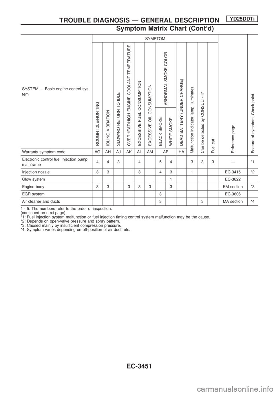
SYSTEM Ð Basic engine control sys-
temSYMPTOM
Reference page
Feature of symptom, Check pointROUGH IDLE/HUNTING
IDLING VIBRATION
SLOW/NO RETURN TO IDLE
OVERHEAT/HIGH ENGINE COOLANT TEMPERATURE
EXCESSIVE FUEL CONSUMPTION
EXCESSIVE OIL CONSUMPTION
ABNORMAL SMOKE COLOR
DEAD BATTERY (UNDER CHARGE)
Malfunction indicator lamp illuminates.
Can be detected by CONSULT-II?
Fuel cutBLACK SMOKE
WHITE SMOKEWarranty symptom code AG AH AJ AK AL AM AP HA
Electronic control fuel injection pump
mainframe443 4 54 333 Ð *1
Injection nozzle 3 3 3 4 3 1 EC-3415 *2
Glow system 1 EC-3622
Engine body 3 3 3 3 3 3 EM section *3
EGR system 3 EC-3606
Air cleaner and ducts 3 3 MA section *4
1 - 5: The numbers refer to the order of inspection.
(continued on next page)
*1: Fuel injection system malfunction or fuel injection timing control system malfunction may be the cause.
*2: Depends on open-valve pressure and spray pattern.
*3: Caused mainly by insufficient compression pressure.
*4: Symptom varies depending on off-position of air duct, etc.
TROUBLE DIAGNOSIS Ð GENERAL DESCRIPTIONYD25DDTi
Symptom Matrix Chart (Cont'd)
EC-3451
Page 478 of 1306
SYSTEM Ð ENGINE CONTROL system
Malfunction
SYMPTOM
Reference page
Feature of symptom, Check pointROUGH IDLE/HUNTING
IDLING VIBRATION
SLOW/NO RETURN TO IDLE
OVERHEAT/HIGH ENGINE COOLANT TEMPERATURE
EXCESSIVE FUEL CONSUMPTION
EXCESSIVE OIL CONSUMPTION
ABNORMAL SMOKE COLOR
DEAD BATTERY (UNDER CHARGE)
Malfunction indicator lamp illuminates.
Can be detected by CONSULT-II?
Fuel cutBLACK SMOKE
WHITE SMOKEWarranty symptom code AG AH AJ AK AL AM AP HA
ENGINE CONTROL
Electronic control fuel injection pump
circuit*a, *b 1 1 1
111
Ð
*c, *d 1
Engine coolant temperature sensor
circuit*a, *b 1 1 1 1 1 EC-3481 *1
Vehicle speed sensor circuit *a, *b 1 EC-3485
1 - 5: The numbers refer to the order of inspection.
(continued on next page)
*a: Open
*b: Short
*c: Ground short
*d: Noise
*1: Compensation according to engine coolant temperature does not function.
TROUBLE DIAGNOSIS Ð GENERAL DESCRIPTIONYD25DDTi
Symptom Matrix Chart (Cont'd)
EC-3453
Page 480 of 1306
SYSTEM Ð ENGINE CONTROL system
Malfunction
SYMPTOM
Reference page
Feature of symptom, Check pointROUGH IDLE/HUNTING
IDLING VIBRATION
SLOW/NO RETURN TO IDLE
OVERHEAT/HIGH ENGINE COOLANT TEMPERATURE
EXCESSIVE FUEL CONSUMPTION
EXCESSIVE OIL CONSUMPTION
ABNORMAL SMOKE COLOR
DEAD BATTERY (UNDER CHARGE)
Malfunction indicator lamp illuminates.
Can be detected by CONSULT-II?
Fuel cutBLACK SMOKE
WHITE SMOKEWarranty symptom code AG AH AJ AK AL AM AP HA
ENGINE CONTROL
Fuel cut system line*a, *c 1 1
EC-3615
*b 1 *2
Accelerator position sensor circuit *a, *b 1 1 EC-3516
Crankshaft position sensor (TDC) cir-
cuit*a, *b,
*d1 1 1 1 EC-3535
Charge air pressure sensor circuit*a, *c
1 EC-3601
*b 1
1 - 5: The numbers refer to the order of inspection.
(continued on next page)
*a: Open
*b: Short
*c: Ground short
*d: Noise
*2: Engine runs on after turning ignition switch OFF.
TROUBLE DIAGNOSIS Ð GENERAL DESCRIPTIONYD25DDTi
Symptom Matrix Chart (Cont'd)
EC-3455
Page 482 of 1306
SYSTEM Ð ENGINE CONTROL system
Malfunction
SYMPTOM
Reference page
Feature of symptom, Check pointROUGH IDLE/HUNTING
IDLING VIBRATION
SLOW/NO RETURN TO IDLE
OVERHEAT/HIGH ENGINE COOLANT TEMPERATURE
EXCESSIVE FUEL CONSUMPTION
EXCESSIVE OIL CONSUMPTION
ABNORMAL SMOKE COLOR
DEAD BATTERY (UNDER CHARGE)
Malfunction indicator lamp illuminates.
Can be detected by CONSULT-II?
Fuel cutBLACK SMOKE
WHITE SMOKEWarranty symptom code AG AH AJ AK AL AM AP HA
ENGINE CONTROL
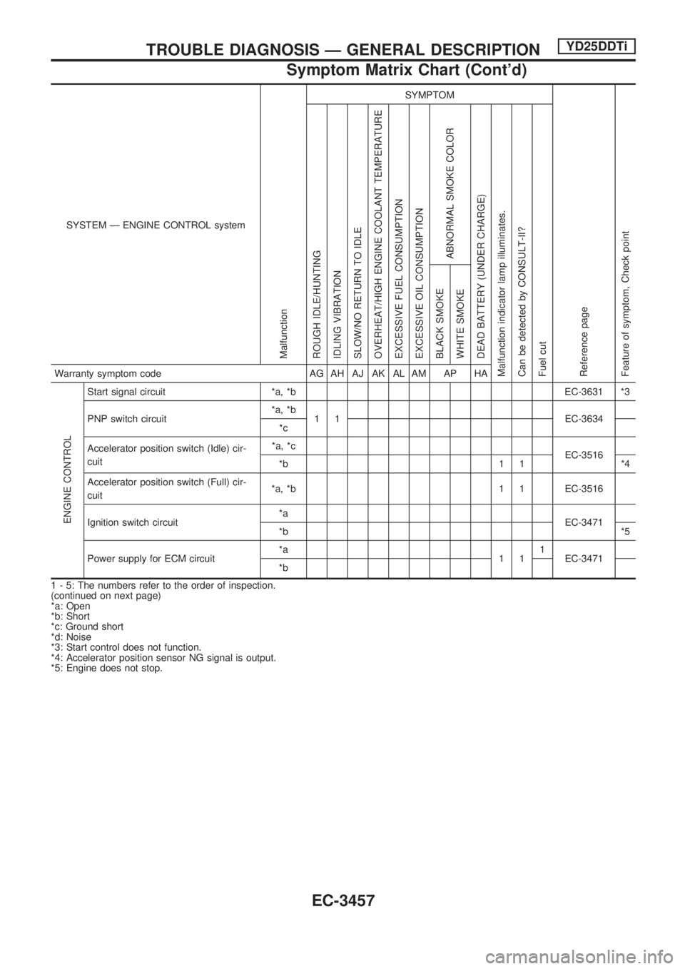
Start signal circuit *a, *b EC-3631 *3
PNP switch circuit*a, *b
1 1 EC-3634
*c
Accelerator position switch (Idle) cir-
cuit*a, *c
EC-3516
*b 1 1 *4
Accelerator position switch (Full) cir-
cuit*a, *b 1 1 EC-3516
Ignition switch circuit*a
EC-3471
*b*5
Power supply for ECM circuit*a
111
EC-3471
*b
1 - 5: The numbers refer to the order of inspection.
(continued on next page)
*a: Open
*b: Short
*c: Ground short
*d: Noise
*3: Start control does not function.
*4: Accelerator position sensor NG signal is output.
*5: Engine does not stop.
TROUBLE DIAGNOSIS Ð GENERAL DESCRIPTIONYD25DDTi
Symptom Matrix Chart (Cont'd)
EC-3457
Page 484 of 1306
SYSTEM Ð ENGINE CONTROL system
Malfunction
SYMPTOM
Reference page
Feature of symptom, Check pointROUGH IDLE/HUNTING
IDLING VIBRATION
SLOW/NO RETURN TO IDLE
OVERHEAT/HIGH ENGINE COOLANT TEMPERATURE
EXCESSIVE FUEL CONSUMPTION
EXCESSIVE OIL CONSUMPTION
ABNORMAL SMOKE COLOR
DEAD BATTERY (UNDER CHARGE)
Malfunction indicator lamp illuminates.
Can be detected by CONSULT-II?
Fuel cutBLACK SMOKE
WHITE SMOKEWarranty symptom code AG AH AJ AK AL AM AP HA
ENGINE CONTROL
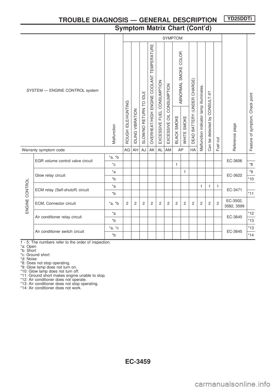
EGR volume control valve circuit*a, *b
EC-3606
*c 1 *8
Glow relay circuit*a 1
EC-3622*9
*b*10
ECM relay (Self-shutoff) circuit*a 111
EC-3471
*b*11
ECM, Connector circuit *a, *b222222222222EC-3502,
3582, 3599
Air conditioner relay circuit*a
EC-3645*12
*b*13
Air conditioner switch circuit*a, *c
EC-3645*13
*b*14
1 - 5: The numbers refer to the order of inspection.
*a: Open
*b: Short
*c: Ground short
*d: Noise
*8: Does not stop operating.
*9: Glow lamp does not turn on.
*10: Glow lamp does not turn off.
*11: Ground short makes engine unable to stop.
*12: Air conditioner does not operate.
*13: Air conditioner does not stop operating.
*14: Air conditioner does not work.
TROUBLE DIAGNOSIS Ð GENERAL DESCRIPTIONYD25DDTi
Symptom Matrix Chart (Cont'd)
EC-3459
Page 515 of 1306
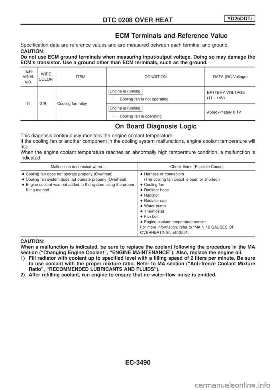
ECM Terminals and Reference Value
Specification data are reference values and are measured between each terminal and ground.
CAUTION:
Do not use ECM ground terminals when measuring input/output voltage. Doing so may damage the
ECM's transistor. Use a ground other than ECM terminals, such as the ground.
TER-
MINAL
NO.WIRE
COLORITEM CONDITION DATA (DC Voltage)
14 G/B Cooling fan relayEngine is running.
Cooling fan is not operatingBATTERY VOLTAGE
(11 - 14V)
Engine is running.
Cooling fan is operatingApproximately 0.1V
On Board Diagnosis Logic
This diagnosis continuously monitors the engine coolant temperature.
If the cooling fan or another component in the cooling system malfunctions, engine coolant temperature will
rise.
When the engine coolant temperature reaches an abnormally high temperature condition, a malfunction is
indicated.
Malfunction is detected when ... Check Items (Possible Cause)
+Cooling fan does not operate properly (Overheat).
+Cooling fan system does not operate properly (Overheat).
+Engine coolant was not added to the system using the proper
filling method.+Harness or connectors
(The cooling fan circuit is open or shorted.)
+Cooling fan
+Radiator hose
+Radiator
+Radiator cap
+Water pump
+Thermostat
+Fan belt
+Engine coolant temperature sensor
For more information, refer to ªMAIN 12 CAUSES OF
OVERHEATINGº, EC-3501.
CAUTION:
When a malfunction is indicated, be sure to replace the coolant following the procedure in the MA
section (ªChanging Engine Coolantº, ªENGINE MAINTENANCEº). Also, replace the engine oil.
1) Fill radiator with coolant up to specified level with a filling speed of 2 liters per minute. Be sure
to use coolant with the proper mixture ratio. Refer to MA section (ªAnti-freeze Coolant Mixture
Ratioº, ªRECOMMENDED LUBRICANTS AND FLUIDSº).
2) After refilling coolant, run engine to ensure that no water-flow noise is emitted.
DTC 0208 OVER HEATYD25DDTi
EC-3490