2001 NISSAN PICK-UP battery replacement
[x] Cancel search: battery replacementPage 1093 of 1306
![NISSAN PICK-UP 2001 Repair Manual If no malfunction is detected on ªSELF-DIAG [CURRENT]º even
though malfunction is detected by the ªAIR BAGº warning lamp,
check the battery voltage.
If the battery voltage is less than 9V, charge NISSAN PICK-UP 2001 Repair Manual If no malfunction is detected on ªSELF-DIAG [CURRENT]º even
though malfunction is detected by the ªAIR BAGº warning lamp,
check the battery voltage.
If the battery voltage is less than 9V, charge](/manual-img/5/57372/w960_57372-1092.png)
If no malfunction is detected on ªSELF-DIAG [CURRENT]º even
though malfunction is detected by the ªAIR BAGº warning lamp,
check the battery voltage.
If the battery voltage is less than 9V, charge the battery. Then
go to DIAGNOSTIC PROCEDURE 4 for final checking, page
RS-3028.
If the battery voltage is OK, go to DIAGNOSTIC PROCEDURE
6, page RS-3032, to diagnose the following situations:
+Self-diagnostic result (previously stored in the memory)
might not be erased after repair.
+The SRS system malfunctions intermittently.
8. Touch ªPRINTº.
9. Compare diagnostic codes to the CONSULT-II DIAGNOS-
TIC CODE CHART, page RS-3023.
10. Touch ªBACKº key of CONSULT-II until ªSELECT SYSTEMº
appears in order to return to User mode from Diagnosis
mode.
11. Turn ignition switch ªOFFº, then turn off and disconnect
CONSULT-II and both battery cables.
12. Repair the system as outlined by the ªRepair orderº in CON-
SULT-II DIAGNOSTIC CODE CHART, that corresponds to
the self-diagnostic result. For replacement procedure of com-
ponent parts, refer to RS-3005 and ªRemoval and Installa-
tionº in RS section of Service Manual (Pub. No. SM9E-
D22BG0) for details.
13. After repairing the system, go to DIAGNOSTIC PROCE-
DURE 4 for final checking, page RS-3028.
SRS701
TROUBLE DIAGNOSES Ð Supplemental Restraint System (SRS)
Self-diagnosis (Cont'd)
RS-3022
Page 1094 of 1306
![NISSAN PICK-UP 2001 Repair Manual CONSULT-II DIAGNOSTIC CODE CHART (ªSELF-DIAG [CURRENT]º)
Diagnostic item ExplanationRepair order
Recheck SRS at each
replacement.
NO DTC IS DETECTED When malfunction is indicated
by the ªAIR BAGº NISSAN PICK-UP 2001 Repair Manual CONSULT-II DIAGNOSTIC CODE CHART (ªSELF-DIAG [CURRENT]º)
Diagnostic item ExplanationRepair order
Recheck SRS at each
replacement.
NO DTC IS DETECTED When malfunction is indicated
by the ªAIR BAGº](/manual-img/5/57372/w960_57372-1093.png)
CONSULT-II DIAGNOSTIC CODE CHART (ªSELF-DIAG [CURRENT]º)
Diagnostic item ExplanationRepair order
Recheck SRS at each
replacement.
NO DTC IS DETECTED When malfunction is indicated
by the ªAIR BAGº warning lamp
in User mode+Low battery voltage (Less
than 9V)+Go to DIAGNOSTIC PROCE-
DURE 4 (RS-3028) after
charging battery.
+Self-diagnostic result ªSELF-
DIAG [PAST]º (previously
stored in the memory) might
not be erased after repair.
+Intemittent malfunction has
been detected in the past.+Go to DIAGNOSTIC PROCE-
DURE 6 (RS-3032).
+No malfunction is detected.+Go to DIAGNOSTIC PROCE-
DURE 4 (RS-3028).
DRIVER AIRBAG MOD-
ULE
[OPEN]+Driver air bag module circuit is open. (including the spiral cable) 1. Visually check the wiring har-
ness connection.
2. Replace the harness if it has
visible damage.
3. Replace the spiral cable.
4. Replace driver air bag mod-
ule.
(Before disposal, it must be
deployed.)
5. Replace the diagnosis sensor
unit.
6. Replace the related harness. DRIVER AIRBAG MOD-
ULE
[VB-SHORT]+Driver air bag module circuit is shorted to a power supply circuit.
(including the spiral cable)
DRIVER AIRBAG MOD-
ULE
[GND-SHORT]+Driver air bag module circuit is shorted to ground. (including the
spiral cable)
DRIVER AIRBAG MOD-
ULE
[SHORT]+Driver air bag module circuits are shorted to each other.
ASSIST A/B MODULE
[VB-SHORT]+Front passenger air bag module circuit is shorted to a power sup-
ply circuit.1. Visually check the wiring har-
ness connection.
2. Replace the harness if it has
visible damage.
3. Replace front passenger air
bag module.
(Before disposal, it must be
deployed.)
4. Replace the diagnosis sensor
unit.
5. Replace the related harness. ASSIST A/B MODULE
[OPEN]+Front passenger air bag module circuit is open.
ASSIST A/B MODULE
[GND-SHORT]+Front passenger air bag module circuit is shorted to ground.
ASSIST A/B MODULE
[SHORT]+Front passenger air bag module circuits are shorted to each
other.
PRE-TEN FRONT LH
[OPEN]+The circuit for seat belt pre-tensioner (LH) is open. 1. Visually check the wiring har-
ness connections.
2. Replace the harness if it has
visible damage.
3. Replace seat belt (LH).
(Before disposing, it must be
deactivated.)
4. Replace the diagnosis sensor
unit.
5. Replace the related harness. PRE-TEN FRONT LH
[VB-SHORT]+The circuit for seat belt pre-tensioner (LH) is shorted to a power
supply circuit.
PRE-TEN FRONT LH
[GND-SHORT]+The circuit for seat belt pre-tensioner (LH) is shorted to ground.
PRE-TEN FRONT RH
[OPEN/VB-SHORT]+The circuit for seat belt pre-tensioner (RH) is open or shorted to
some power supply circuit.1. Visually check the wiring har-
ness connections.
2. Replace the harness if it has
visible damage.
3. Replace seat belt (RH).
(Before disposing, it must be
deactivated.)
4. Replace the diagnosis sensor
unit.
5. Replace the related harness. PRE-TEN FRONT RH
[VB-SHORT]+The circuit for seat belt pre-tensioner (RH) is shorted to a power
supply circuit.
PRE-TEN FRONT RH
[GND-SHORT]+The circuit for front RH pre-tensioner is shorted to ground.
* Follow the procedures in numerical order when repairing malfunctioning parts. Confirm whether malfunction is eliminated
using the air bag warning lamp or CONSULT-II each time repair is finished. If malfunction is still observed, proceed to the
next step. When malfunction is eliminated, further repair work is not required.
TROUBLE DIAGNOSES Ð Supplemental Restraint System (SRS)
Self-diagnosis (Cont'd)
RS-3023
Page 1096 of 1306
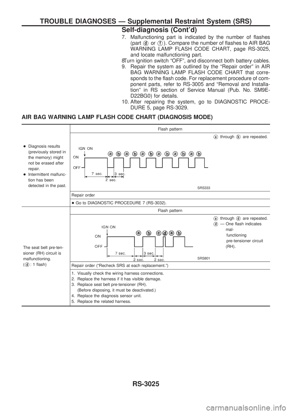
7. Malfunctioning part is indicated by the number of flashes
(part
VdorVf). Compare the number of flashes to AIR BAG
WARNING LAMP FLASH CODE CHART, page RS-3025,
and locate malfunctioning part.
8.Turn ignition switch ªOFFº, and disconnect both battery cables.
9. Repair the system as outlined by the ªRepair orderº in AIR
BAG WARNING LAMP FLASH CODE CHART that corre-
sponds to the flash code. For replacement procedure of com-
ponent parts, refer to RS-3005 and ªRemoval and Installa-
tionº in RS section of Service Manual (Pub. No. SM9E-
D22BG0) for details.
10. After repairing the system, go to DIAGNOSTIC PROCE-
DURE 5, page RS-3029.
AIR BAG WARNING LAMP FLASH CODE CHART (DIAGNOSIS MODE)
+Diagnosis results
(previously stored in
the memory) might
not be erased after
repair.
+Intermittent malfunc-
tion has been
detected in the past.Flash pattern
SRS333
VathroughVbare repeated.
Repair order
+Go to DIAGNOSTIC PROCEDURE 7 (RS-3032).
The seat belt pre-ten-
sioner (RH) circuit is
malfunctioning.
(
Vd: 1 flash)Flash pattern
SRS801
VathroughVdare repeated.
VdÐ One flash indicates
mal-
functioning
pre-tensioner circuit
(RH).
Repair order (ªRecheck SRS at each replacement.º)
1. Visually check the wiring harness connections.
2. Replace the harness if it has visible damage.
3. Replace seat belt pre-tensioner (RH).
(Before disposing, it must be deactivated.)
4. Replace the diagnosis sensor unit.
5. Replace the related harness.
TROUBLE DIAGNOSES Ð Supplemental Restraint System (SRS)
Self-diagnosis (Cont'd)
RS-3025
Page 1105 of 1306
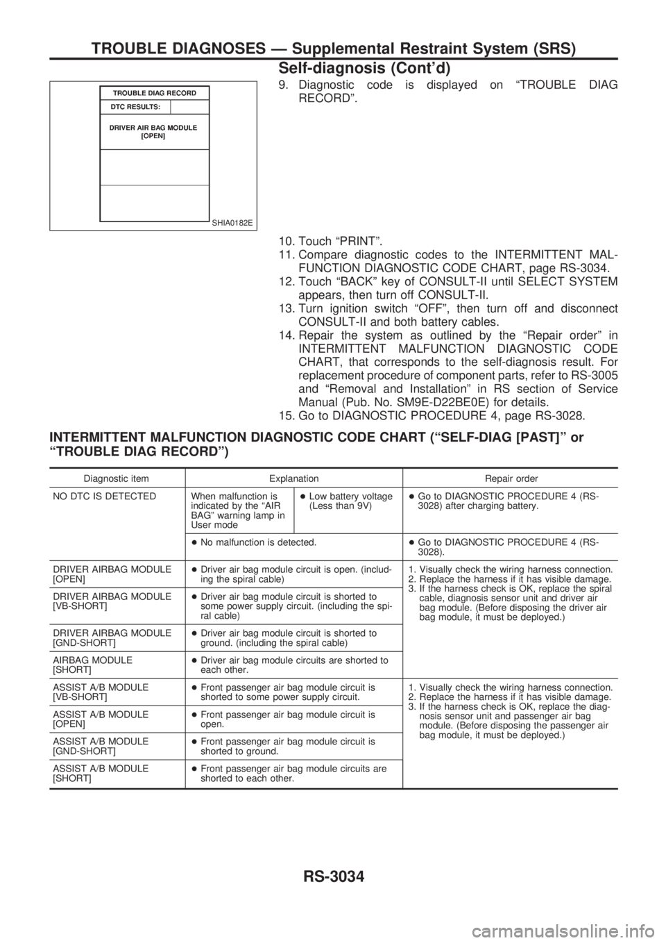
9. Diagnostic code is displayed on ªTROUBLE DIAG
RECORDº.
10. Touch ªPRINTº.
11. Compare diagnostic codes to the INTERMITTENT MAL-
FUNCTION DIAGNOSTIC CODE CHART, page RS-3034.
12. Touch ªBACKº key of CONSULT-II until SELECT SYSTEM
appears, then turn off CONSULT-II.
13. Turn ignition switch ªOFFº, then turn off and disconnect
CONSULT-II and both battery cables.
14. Repair the system as outlined by the ªRepair orderº in
INTERMITTENT MALFUNCTION DIAGNOSTIC CODE
CHART, that corresponds to the self-diagnosis result. For
replacement procedure of component parts, refer to RS-3005
and ªRemoval and Installationº in RS section of Service
Manual (Pub. No. SM9E-D22BE0E) for details.
15. Go to DIAGNOSTIC PROCEDURE 4, page RS-3028.
INTERMITTENT MALFUNCTION DIAGNOSTIC CODE CHART (ªSELF-DIAG [PAST]º or
ªTROUBLE DIAG RECORDº)
Diagnostic item Explanation Repair order
NO DTC IS DETECTED When malfunction is
indicated by the ªAIR
BAGº warning lamp in
User mode+Low battery voltage
(Less than 9V)+Go to DIAGNOSTIC PROCEDURE 4 (RS-
3028) after charging battery.
+No malfunction is detected.+Go to DIAGNOSTIC PROCEDURE 4 (RS-
3028).
DRIVER AIRBAG MODULE
[OPEN]+Driver air bag module circuit is open. (includ-
ing the spiral cable)1. Visually check the wiring harness connection.
2. Replace the harness if it has visible damage.
3. If the harness check is OK, replace the spiral
cable, diagnosis sensor unit and driver air
bag module. (Before disposing the driver air
bag module, it must be deployed.) DRIVER AIRBAG MODULE
[VB-SHORT]+Driver air bag module circuit is shorted to
some power supply circuit. (including the spi-
ral cable)
DRIVER AIRBAG MODULE
[GND-SHORT]+Driver air bag module circuit is shorted to
ground. (including the spiral cable)
AIRBAG MODULE
[SHORT]+Driver air bag module circuits are shorted to
each other.
ASSIST A/B MODULE
[VB-SHORT]+Front passenger air bag module circuit is
shorted to some power supply circuit.1. Visually check the wiring harness connection.
2. Replace the harness if it has visible damage.
3. If the harness check is OK, replace the diag-
nosis sensor unit and passenger air bag
module. (Before disposing the passenger air
bag module, it must be deployed.) ASSIST A/B MODULE
[OPEN]+Front passenger air bag module circuit is
open.
ASSIST A/B MODULE
[GND-SHORT]+Front passenger air bag module circuit is
shorted to ground.
ASSIST A/B MODULE
[SHORT]+Front passenger air bag module circuits are
shorted to each other.
SHIA0182E
TROUBLE DIAGNOSES Ð Supplemental Restraint System (SRS)
Self-diagnosis (Cont'd)
RS-3034
Page 1112 of 1306
ELECTRICAL SYSTEM
SECTION
EL
MODIFICATION NOTICE:
+Wiring diagrams have been changed.
+Combination meter has been changed.
+Headlamp has been changed.
+Headlamp aiming control has been added.
+Headlamp washer has been added.
+A hazard reminder feature has been added to the multi-remote control system.
+NATS (Nissan Anti-Theft System) has been changed.
CONTENTS
PRECAUTIONS................................................... 3004
Supplemental Restraint System (SRS)²AIR
BAG²and²SEAT BELT PRE-TENSIONER².. 3004
POWER SUPPLY ROUTING............................... 3005
Schematic ........................................................ 3005
Wiring Diagram - POWER -............................. 3006
BATTERY............................................................. 3013
Service Data and Specifications (SDS) ........... 3013
STARTING SYSTEM........................................... 3014
Wiring Diagram - START -/M/T Models .......... 3014
Construction ..................................................... 3015
Service Data and Specifications (SDS) ........... 3017
CHARGING SYSTEM.......................................... 3018
Wiring Diagram - CHARGE -/Diesel Engine ... 3018
Wiring Diagram - CHARGE - (KA engine) ...... 3019
Construction ..................................................... 3020
Service Data and Specifications (SDS) ........... 3022
HEADLAMP - Conventional Type -................... 3023
Wiring Diagram - H/LAMP -/LHD Models ........ 3023
Wiring Diagram - H/LAMP -/RHD Models ....... 3025
Bulb Replacement............................................ 3027
Aiming Adjustment ........................................... 3027
Low Beam ........................................................ 3028
HEADLAMP - Daytime Light System -............. 3029
Wiring Diagram - DTRL - ................................. 3029
Bulb Replacement............................................ 3032
Aiming Adjustment ........................................... 3032
HEADLAMP - Dim-dip Lamp System -............. 3033Wiring Diagram - DIMDIP -.............................. 3033
Bulb Replacement............................................ 3036
Aiming Adjustment ........................................... 3036
HEADLAMP - Headlamp Aiming Control -....... 3037
Wiring Diagram - H/AIM - ................................ 3037
PARKING, LICENSE AND TAIL LAMPS........... 3039
Wiring Diagram - TAIL/L -/Except LHD Models
for Europe ........................................................ 3039
Wiring Diagram - TAIL/L -/LHD Models for
Europe.............................................................. 3041
STOP LAMP........................................................ 3043
Wiring Diagram - STOP/L - ............................. 3043
BACK-UP LAMP.................................................. 3044
Wiring Diagram - BACK/L -/M/T Models ......... 3044
REAR FOG LAMP............................................... 3045
Wiring Diagram - R/FOG -/LHD Models .......... 3045
Wiring Diagram - R/FOG -/RHD Models ......... 3046
TURN SIGNAL AND HAZARD WARNING
LAMPS................................................................. 3047
Wiring Diagram - TURN - ................................ 3047
Trouble Diagnoses ........................................... 3049
ILLUMINATION.................................................... 3050
Wiring Diagram - ILL -/LHD Models ................ 3050
Wiring Diagram - ILL -/RHD Models................ 3052
INTERIOR ROOM LAMP..................................... 3054
Wiring Diagram - ROOM/L - ............................ 3054
SPOT LAMP........................................................ 3055
Wiring Diagram - INT/L - ................................. 3055
EL
Page 1113 of 1306
METER AND GAUGES....................................... 3056
System Description .......................................... 3056
Combination Meter/With Tachometer .............. 3057
Combination Meter/Without Tachometer ......... 3058
Schematic/With Tachometer ............................ 3059
Schematic/Without Tachometer ....................... 3060
Construction ..................................................... 3061
Wiring Diagram - METER -/Gasoline Engine
with Tachometer .............................................. 3062
Wiring Diagram - METER -/Gasoline Engine
without Tachometer ......................................... 3064
Wiring Diagram - METER -/LHD Diesel Engine
Models with Tachometer.................................. 3065
Wiring Diagram - METER -/RHD Diesel
Engine Models with Tachometer ..................... 3067
Wiring Diagram - METER -/Diesel Engine
without Tachometer ......................................... 3069
Meter/Gauge Operation and Odo/Trip Meter
Segment Check in Diagnosis Mode ................ 3070
Trouble Diagnoses/With Tachometer .............. 3071
Trouble Diagnoses/Without Tachometer ......... 3076
WARNING LAMPS.............................................. 3081
Schematic/With Tachometer ............................ 3081
Schematic/Without Tachometer ....................... 3082
Wiring Diagram - WARN -/Gasoline Engine
with Tachometer .............................................. 3083
Wiring Diagram - WARN -/Gasoline Engine
without Tachometer ......................................... 3087
Wiring Diagram - WARN -/Diesel Engine with
Tachometer ...................................................... 3091
Wiring Diagram - WARN -/Diesel Engine
without Tachometer ......................................... 3095
A/T INDICATOR................................................... 3100
Wiring Diagram - AT/IND -/RHD Models ......... 3100
Wiring Diagram - CHIME -/LHD Models.......... 3101
Wiring Diagram - CHIME -/RHD Models ......... 3102
FRONT WIPER AND WASHER.......................... 3103
Wiring Diagram - WIPER -/Without Intermittent
for Floor-shift .................................................... 3103
Wiring Diagram - WIPER -/Without Intermittent
for RHD Column-shift Models .......................... 3106
HEADLAMP WASHER........................................ 3108
Wiring Diagram - HLC - ................................... 3108
HORN................................................................... 3109
Wiring Diagram - HORN -................................ 3109
CIGARETTE LIGHTER........................................ 3110
Wiring Diagram - CIGAR - ............................... 3110
CLOCK................................................................. 3111
Wiring Diagram - CLOCK - .............................. 3111
REAR WINDOW DEFOGGER AND MIRROR
DEFOGGER......................................................... 3112
Wiring Diagram - DEF - ................................... 3112
AUDIO.................................................................. 3113
Wiring Diagram - AUDIO -/LHD Models .......... 3113Wiring Diagram - AUDIO -/RHD Models ......... 3114
AUDIO ANTENNA............................................... 3115
Power Antenna/Wiring Diagram - P/ANT - ...... 3115
POWER DOOR MIRROR.................................... 3116
Wiring Diagram - MIRROR -/LHD Models....... 3116
Wiring Diagram - MIRROR -/RHD Models ...... 3117
HEATED SEAT.................................................... 3118
Wiring Diagram - H/SEAT - ............................. 3118
POWER WINDOW............................................... 3120
Schematic/Without Interruption Detection
Function ........................................................... 3120
Schematic/With Interruption Detection
Function ........................................................... 3121
Wiring Diagram - WINDOW -/Without
Interruption Detection Function........................ 3122
Wiring Diagram - WINDOW -/With Interruption
Detection Function ........................................... 3126
Trouble Diagnoses/Without Interruption
Detection Function ........................................... 3130
Trouble Diagnoses/With Interruption Detection
Function ........................................................... 3131
POWER DOOR LOCK......................................... 3133
Wiring Diagram - D/LOCK - ............................. 3133
MULTI-REMOTE CONTROL SYSTEM............... 3135
System Description .......................................... 3135
MULTI-REMOTE CONTROL SYSTEM............... 3136
Wiring Diagram - MULTI - ............................... 3136
Trouble Diagnoses ........................................... 3137
ID Code Entry Procedure ................................ 3139
Remote Controller Battery Replacement ......... 3140
THEFT WARNING SYSTEM............................... 3141
Wiring Diagram - PRWIRE - ............................ 3141
NATS (Nissan Anti-Theft System).................... 3142
Component Parts and Harness Connector
Location............................................................ 3142
System Description .......................................... 3143
System Composition ........................................ 3144
Wiring Diagram - NATS -/LHD Models............ 3145
Wiring Diagram - NATS -/RHD Diesel Engine
Models.............................................................. 3146
CONSULT-II ..................................................... 3147
Trouble Diagnoses ........................................... 3149
How to Replace NATS IMMU .......................... 3160
LOCATION OF ELECTRICAL UNITS................. 3161
Engine Compartment ....................................... 3161
Passenger Compartment ................................. 3162
HARNESS LAYOUT............................................ 3164
Main Harness ................................................... 3164
Engine Room Harness..................................... 3174
Engine Control Harness/KA engine ................. 3182
Engine Control Harness................................... 3184
Engine Harness ............................................... 3185
Alternator Harness ........................................... 3187
Instrument Harness.......................................... 3189
EL-3002
Page 1138 of 1306
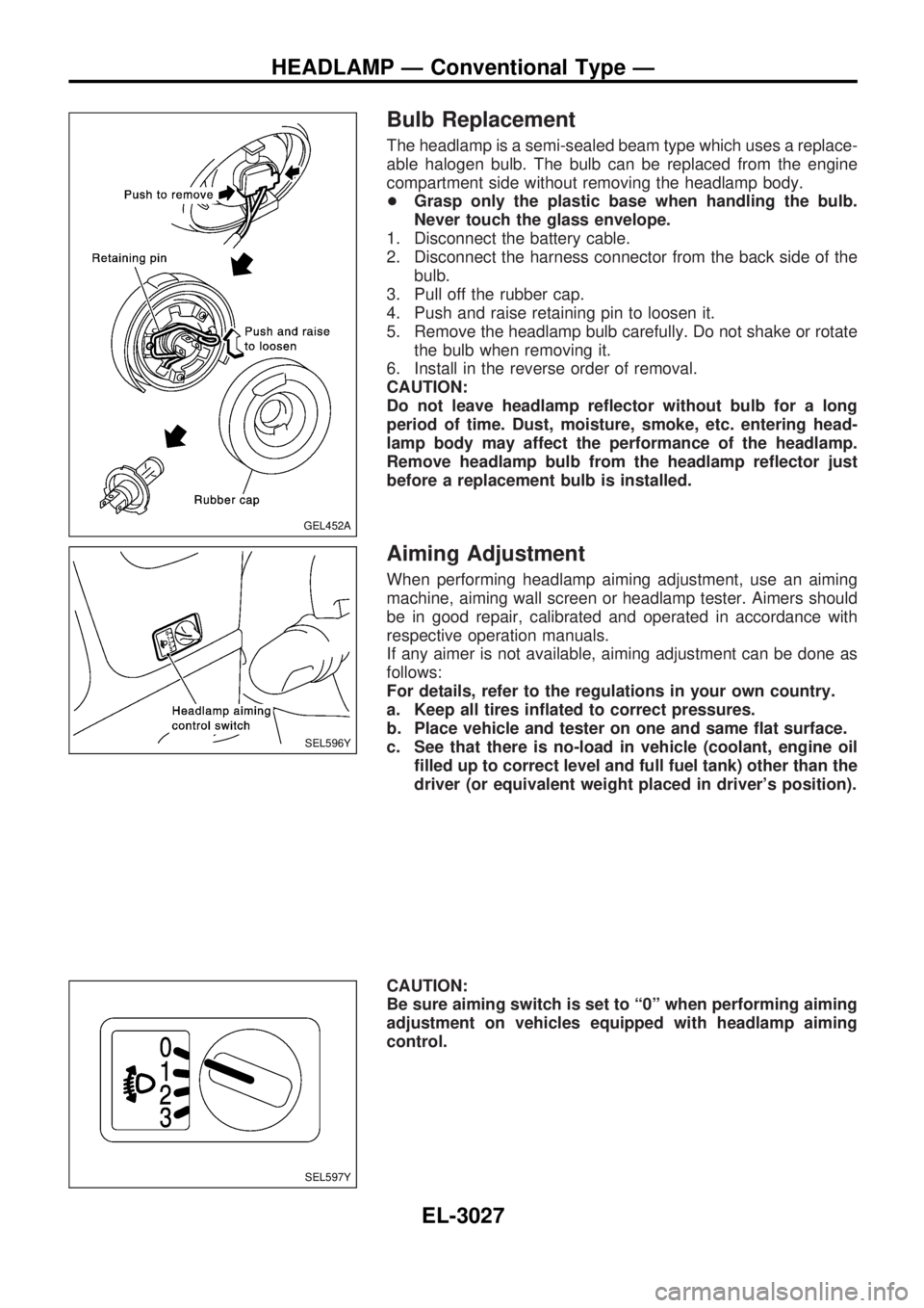
Bulb Replacement
The headlamp is a semi-sealed beam type which uses a replace-
able halogen bulb. The bulb can be replaced from the engine
compartment side without removing the headlamp body.
+Grasp only the plastic base when handling the bulb.
Never touch the glass envelope.
1. Disconnect the battery cable.
2. Disconnect the harness connector from the back side of the
bulb.
3. Pull off the rubber cap.
4. Push and raise retaining pin to loosen it.
5. Remove the headlamp bulb carefully. Do not shake or rotate
the bulb when removing it.
6. Install in the reverse order of removal.
CAUTION:
Do not leave headlamp reflector without bulb for a long
period of time. Dust, moisture, smoke, etc. entering head-
lamp body may affect the performance of the headlamp.
Remove headlamp bulb from the headlamp reflector just
before a replacement bulb is installed.
Aiming Adjustment
When performing headlamp aiming adjustment, use an aiming
machine, aiming wall screen or headlamp tester. Aimers should
be in good repair, calibrated and operated in accordance with
respective operation manuals.
If any aimer is not available, aiming adjustment can be done as
follows:
For details, refer to the regulations in your own country.
a. Keep all tires inflated to correct pressures.
b. Place vehicle and tester on one and same flat surface.
c. See that there is no-load in vehicle (coolant, engine oil
filled up to correct level and full fuel tank) other than the
driver (or equivalent weight placed in driver's position).
CAUTION:
Be sure aiming switch is set to ª0º when performing aiming
adjustment on vehicles equipped with headlamp aiming
control.
GEL452A
SEL596Y
SEL597Y
HEADLAMP Ð Conventional Type Ð
EL-3027
Page 1251 of 1306
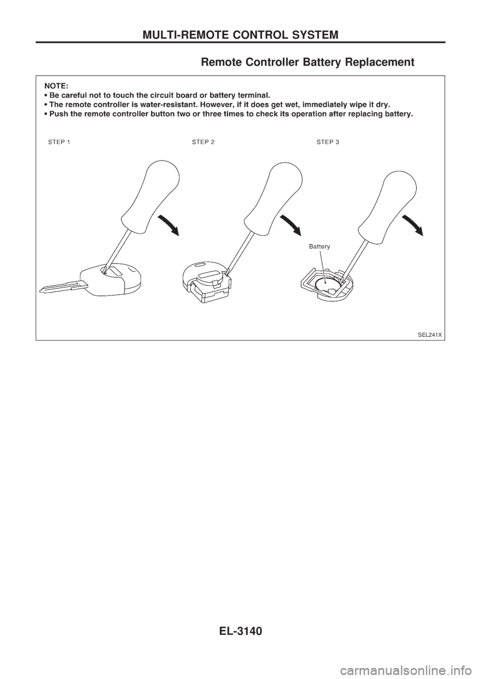
Remote Controller Battery Replacement
SEL241X
MULTI-REMOTE CONTROL SYSTEM
EL-3140