2001 NISSAN PICK-UP battery replacement
[x] Cancel search: battery replacementPage 676 of 1306

ELECTRICAL SYSTEM
SECTION
EL
MODIFICATION NOTICE:
+Wiring diagrams have been changed.
+Combination meter has been changed.
+Headlamp has been changed.
+Headlamp aiming control has been added.
+Headlamp washer has been added.
+A hazard reminder feature has been added to the multi-remote control system.
+NATS (Nissan Anti-Theft System) has been changed.
CONTENTS
PRECAUTIONS................................................... 3004
Supplemental Restraint System (SRS)²AIR
BAG²and²SEAT BELT PRE-TENSIONER².. 3004
POWER SUPPLY ROUTING............................... 3005
Schematic ........................................................ 3005
Wiring Diagram - POWER -............................. 3006
BATTERY............................................................. 3013
Service Data and Specifications (SDS) ........... 3013
STARTING SYSTEM........................................... 3014
Wiring Diagram - START -/M/T Models .......... 3014
Construction ..................................................... 3015
Service Data and Specifications (SDS) ........... 3017
CHARGING SYSTEM.......................................... 3018
Wiring Diagram - CHARGE -/Diesel Engine ... 3018
Wiring Diagram - CHARGE - (KA engine) ...... 3019
Construction ..................................................... 3020
Service Data and Specifications (SDS) ........... 3022
HEADLAMP - Conventional Type -................... 3023
Wiring Diagram - H/LAMP -/LHD Models ........ 3023
Wiring Diagram - H/LAMP -/RHD Models ....... 3025
Bulb Replacement............................................ 3027
Aiming Adjustment ........................................... 3027
Low Beam ........................................................ 3028
HEADLAMP - Daytime Light System -............. 3029
Wiring Diagram - DTRL - ................................. 3029
Bulb Replacement............................................ 3032
Aiming Adjustment ........................................... 3032
HEADLAMP - Dim-dip Lamp System -............. 3033Wiring Diagram - DIMDIP -.............................. 3033
Bulb Replacement............................................ 3036
Aiming Adjustment ........................................... 3036
HEADLAMP - Headlamp Aiming Control -....... 3037
Wiring Diagram - H/AIM - ................................ 3037
PARKING, LICENSE AND TAIL LAMPS........... 3039
Wiring Diagram - TAIL/L -/Except LHD Models
for Europe ........................................................ 3039
Wiring Diagram - TAIL/L -/LHD Models for
Europe.............................................................. 3041
STOP LAMP........................................................ 3043
Wiring Diagram - STOP/L - ............................. 3043
BACK-UP LAMP.................................................. 3044
Wiring Diagram - BACK/L -/M/T Models ......... 3044
REAR FOG LAMP............................................... 3045
Wiring Diagram - R/FOG -/LHD Models .......... 3045
Wiring Diagram - R/FOG -/RHD Models ......... 3046
TURN SIGNAL AND HAZARD WARNING
LAMPS................................................................. 3047
Wiring Diagram - TURN - ................................ 3047
Trouble Diagnoses ........................................... 3049
ILLUMINATION.................................................... 3050
Wiring Diagram - ILL -/LHD Models ................ 3050
Wiring Diagram - ILL -/RHD Models................ 3052
INTERIOR ROOM LAMP..................................... 3054
Wiring Diagram - ROOM/L - ............................ 3054
SPOT LAMP........................................................ 3055
Wiring Diagram - INT/L - ................................. 3055
EL
Page 677 of 1306

METER AND GAUGES....................................... 3056
System Description .......................................... 3056
Combination Meter/With Tachometer .............. 3057
Combination Meter/Without Tachometer ......... 3058
Schematic/With Tachometer ............................ 3059
Schematic/Without Tachometer ....................... 3060
Construction ..................................................... 3061
Wiring Diagram - METER -/Gasoline Engine
with Tachometer .............................................. 3062
Wiring Diagram - METER -/Gasoline Engine
without Tachometer ......................................... 3064
Wiring Diagram - METER -/LHD Diesel Engine
Models with Tachometer.................................. 3065
Wiring Diagram - METER -/RHD Diesel
Engine Models with Tachometer ..................... 3067
Wiring Diagram - METER -/Diesel Engine
without Tachometer ......................................... 3069
Meter/Gauge Operation and Odo/Trip Meter
Segment Check in Diagnosis Mode ................ 3070
Trouble Diagnoses/With Tachometer .............. 3071
Trouble Diagnoses/Without Tachometer ......... 3076
WARNING LAMPS.............................................. 3081
Schematic/With Tachometer ............................ 3081
Schematic/Without Tachometer ....................... 3082
Wiring Diagram - WARN -/Gasoline Engine
with Tachometer .............................................. 3083
Wiring Diagram - WARN -/Gasoline Engine
without Tachometer ......................................... 3087
Wiring Diagram - WARN -/Diesel Engine with
Tachometer ...................................................... 3091
Wiring Diagram - WARN -/Diesel Engine
without Tachometer ......................................... 3095
A/T INDICATOR................................................... 3100
Wiring Diagram - AT/IND -/RHD Models ......... 3100
Wiring Diagram - CHIME -/LHD Models.......... 3101
Wiring Diagram - CHIME -/RHD Models ......... 3102
FRONT WIPER AND WASHER.......................... 3103
Wiring Diagram - WIPER -/Without Intermittent
for Floor-shift .................................................... 3103
Wiring Diagram - WIPER -/Without Intermittent
for RHD Column-shift Models .......................... 3106
HEADLAMP WASHER........................................ 3108
Wiring Diagram - HLC - ................................... 3108
HORN................................................................... 3109
Wiring Diagram - HORN -................................ 3109
CIGARETTE LIGHTER........................................ 3110
Wiring Diagram - CIGAR - ............................... 3110
CLOCK................................................................. 3111
Wiring Diagram - CLOCK - .............................. 3111
REAR WINDOW DEFOGGER AND MIRROR
DEFOGGER......................................................... 3112
Wiring Diagram - DEF - ................................... 3112
AUDIO.................................................................. 3113
Wiring Diagram - AUDIO -/LHD Models .......... 3113Wiring Diagram - AUDIO -/RHD Models ......... 3114
AUDIO ANTENNA............................................... 3115
Power Antenna/Wiring Diagram - P/ANT - ...... 3115
POWER DOOR MIRROR.................................... 3116
Wiring Diagram - MIRROR -/LHD Models....... 3116
Wiring Diagram - MIRROR -/RHD Models ...... 3117
HEATED SEAT.................................................... 3118
Wiring Diagram - H/SEAT - ............................. 3118
POWER WINDOW............................................... 3120
Schematic/Without Interruption Detection
Function ........................................................... 3120
Schematic/With Interruption Detection
Function ........................................................... 3121
Wiring Diagram - WINDOW -/Without
Interruption Detection Function........................ 3122
Wiring Diagram - WINDOW -/With Interruption
Detection Function ........................................... 3126
Trouble Diagnoses/Without Interruption
Detection Function ........................................... 3130
Trouble Diagnoses/With Interruption Detection
Function ........................................................... 3131
POWER DOOR LOCK......................................... 3133
Wiring Diagram - D/LOCK - ............................. 3133
MULTI-REMOTE CONTROL SYSTEM............... 3135
System Description .......................................... 3135
MULTI-REMOTE CONTROL SYSTEM............... 3136
Wiring Diagram - MULTI - ............................... 3136
Trouble Diagnoses ........................................... 3137
ID Code Entry Procedure ................................ 3139
Remote Controller Battery Replacement ......... 3140
THEFT WARNING SYSTEM............................... 3141
Wiring Diagram - PRWIRE - ............................ 3141
NATS (Nissan Anti-Theft System).................... 3142
Component Parts and Harness Connector
Location............................................................ 3142
System Description .......................................... 3143
System Composition ........................................ 3144
Wiring Diagram - NATS -/LHD Models............ 3145
Wiring Diagram - NATS -/RHD Diesel Engine
Models.............................................................. 3146
CONSULT-II ..................................................... 3147
Trouble Diagnoses ........................................... 3149
How to Replace NATS IMMU .......................... 3160
LOCATION OF ELECTRICAL UNITS................. 3161
Engine Compartment ....................................... 3161
Passenger Compartment ................................. 3162
HARNESS LAYOUT............................................ 3164
Main Harness ................................................... 3164
Engine Room Harness..................................... 3174
Engine Control Harness/KA engine ................. 3182
Engine Control Harness................................... 3184
Engine Harness ............................................... 3185
Alternator Harness ........................................... 3187
Instrument Harness.......................................... 3189
EL-3002
Page 702 of 1306
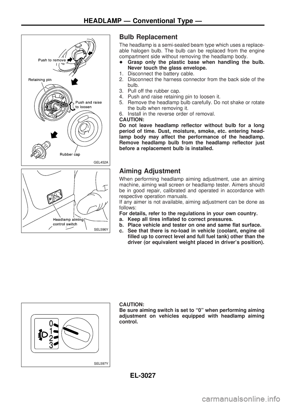
Bulb Replacement
The headlamp is a semi-sealed beam type which uses a replace-
able halogen bulb. The bulb can be replaced from the engine
compartment side without removing the headlamp body.
+Grasp only the plastic base when handling the bulb.
Never touch the glass envelope.
1. Disconnect the battery cable.
2. Disconnect the harness connector from the back side of the
bulb.
3. Pull off the rubber cap.
4. Push and raise retaining pin to loosen it.
5. Remove the headlamp bulb carefully. Do not shake or rotate
the bulb when removing it.
6. Install in the reverse order of removal.
CAUTION:
Do not leave headlamp reflector without bulb for a long
period of time. Dust, moisture, smoke, etc. entering head-
lamp body may affect the performance of the headlamp.
Remove headlamp bulb from the headlamp reflector just
before a replacement bulb is installed.
Aiming Adjustment
When performing headlamp aiming adjustment, use an aiming
machine, aiming wall screen or headlamp tester. Aimers should
be in good repair, calibrated and operated in accordance with
respective operation manuals.
If any aimer is not available, aiming adjustment can be done as
follows:
For details, refer to the regulations in your own country.
a. Keep all tires inflated to correct pressures.
b. Place vehicle and tester on one and same flat surface.
c. See that there is no-load in vehicle (coolant, engine oil
filled up to correct level and full fuel tank) other than the
driver (or equivalent weight placed in driver's position).
CAUTION:
Be sure aiming switch is set to ª0º when performing aiming
adjustment on vehicles equipped with headlamp aiming
control.
GEL452A
SEL596Y
SEL597Y
HEADLAMP Ð Conventional Type Ð
EL-3027
Page 815 of 1306
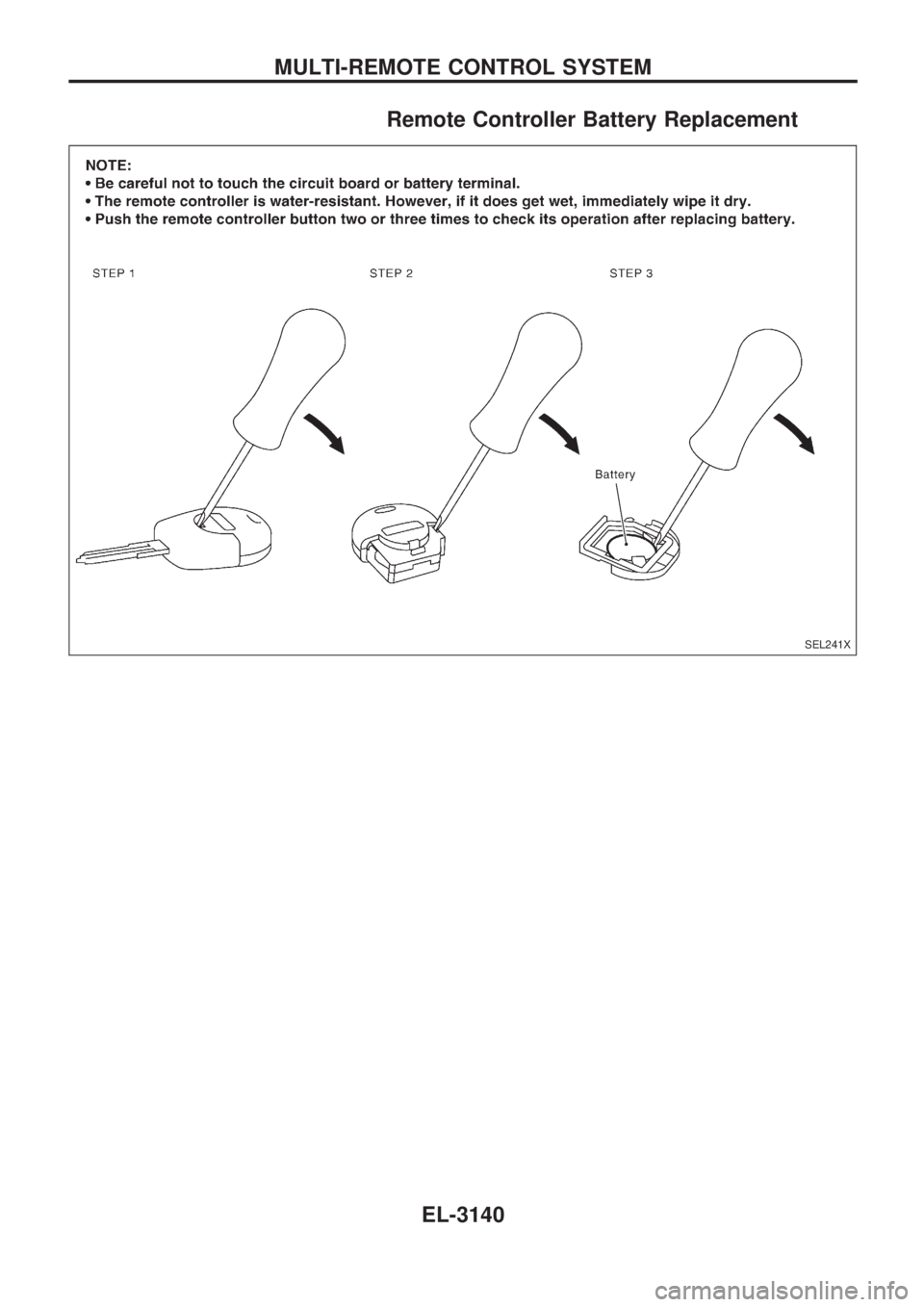
Remote Controller Battery Replacement
SEL241X
MULTI-REMOTE CONTROL SYSTEM
EL-3140
Page 1008 of 1306
GENERAL INFORMATION
SECTION
GI
MODIFICATION NOTICE:
+YD25DDTi engine has been adopted.
+KA24E engine has been replaced with KA24DE engine.
+The appearance design has been changed.
CONTENTS
CONSULT-II CHECKING SYSTEM..................... 3002
Function and System Application .................... 3002
Nickel Metal Hydride Battery Replacement ..... 3002
Checking Equipment ........................................ 3003
CONSULT-II Data Link Connector (DLC)
Circuit ............................................................... 3003IDENTIFICATION INFORMATION...................... 3004
Model Variation ................................................ 3004
Identification Number ....................................... 3005
Wheels and Tires ............................................. 3007
Dimensions ...................................................... 3007
This modification has been included in production starting with the following vehicle identification numbers
(Chassis number):
JN1APGD22U0050001
JN1BPGD22U0030001
JN1APUD22U0030001
JN1BPUD22U0070001
JN1CPUD22U0070001
JN1ADGD22U0020001
JN1BDGD22U0030001
JN1BDUD22U0030001
JN1CDUD22U0030001
JN1CPGD22U0040001
JN1CPGD22U0740101
JN1CDUD22U0740101
JN1CPUD22U0765101
GI
Page 1009 of 1306
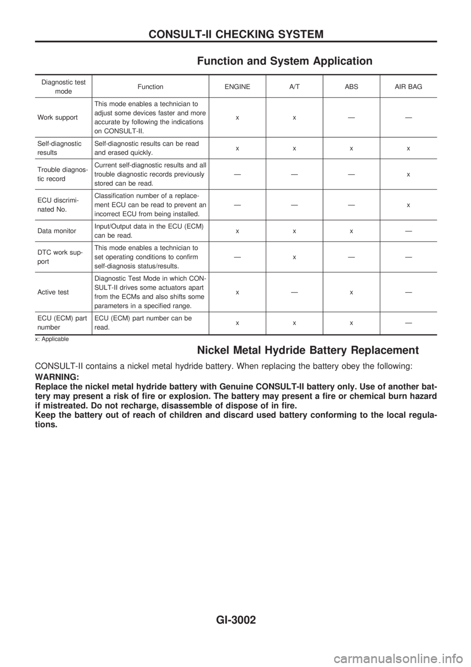
Function and System Application
Diagnostic test
modeFunction ENGINE A/T ABS AIR BAG
Work supportThis mode enables a technician to
adjust some devices faster and more
accurate by following the indications
on CONSULT-II.xxÐÐ
Self-diagnostic
resultsSelf-diagnostic results can be read
and erased quickly.xxxx
Trouble diagnos-
tic recordCurrent self-diagnostic results and all
trouble diagnostic records previously
stored can be read.ÐÐÐ x
ECU discrimi-
nated No.Classification number of a replace-
ment ECU can be read to prevent an
incorrect ECU from being installed.ÐÐÐ x
Data monitorInput/Output data in the ECU (ECM)
can be read.xxxÐ
DTC work sup-
portThis mode enables a technician to
set operating conditions to confirm
self-diagnosis status/results.ÐxÐÐ
Active testDiagnostic Test Mode in which CON-
SULT-II drives some actuators apart
from the ECMs and also shifts some
parameters in a specified range.xÐxÐ
ECU (ECM) part
numberECU (ECM) part number can be
read.xxxÐ
x: Applicable
Nickel Metal Hydride Battery Replacement
CONSULT-II contains a nickel metal hydride battery. When replacing the battery obey the following:
WARNING:
Replace the nickel metal hydride battery with Genuine CONSULT-II battery only. Use of another bat-
tery may present a risk of fire or explosion. The battery may present a fire or chemical burn hazard
if mistreated. Do not recharge, disassemble of dispose of in fire.
Keep the battery out of reach of children and discard used battery conforming to the local regula-
tions.
CONSULT-II CHECKING SYSTEM
GI-3002
Page 1062 of 1306
A
A/C relay ..................................... HA-3019, 3029
A/C trouble diagnoses (auto A/C) ......... HA-3020
A/C trouble diagnoses
(manual A/C) ........................... HA-3004, 3020
A/C, A - Wiring diagram ........................ HA-3021
A/C, M - Wiring diagram ............. HA-3006, 3009
A/T IND - Wiring diagram ...................... EL-3100
AAC/V - Wiring diagram ....................... EC-3298
ABS - Wiring diagram ................. BR-3003, 3010
AT indicator lamp .................................. EL-3100
Accelerator control system .................... FE-3002
Accelerator position sensor ........ EC-3515, 3516
Air bag disposal .................................... RS-3011
Air bag ................................................... RS-3003
Air cleaner filter replacement ..... MA-3010, 3019
Air conditioner cut control . EC-3028, 3413, 3414
Air flow meter - See Mass air flow
sensor ................................................ EC-3151
Alternator ............................................... EL-3022
Angular tightening application .............. EM-3003
Antenna ................................................. EL-3115
Anti-lock brake system - Wiring
diagram ......................... BR-3002, 3003, 3009
Auxiliary air control (AAC) valve ........... EC-3295
B
BACK/L - Wiring diagram ...................... EL-3044
BOOST - Wiring diagram ....................................
Back-up lamp ......................................... EL-3044
Basic inspection ................ EC-3086, 3444, 3445
Battery ................................................... EL-3013
Bumper, front ....................................... BT-3002
C
CHARGE - Wiring diagram ................... EL-3018
CIGAR - Wiring diagram ....................... EL-3110
CKPS - Wiring diagram .............. EC-3266, 3351
CLOCK - Wiring diagram ...................... EL-3111
CMPS - Wiring diagram ........................ EC-3273
CONSULT for engine ....... EC-3070, 3434, 3435
Camshaft inspection ............................. EM-3050
Camshaft position sensor (CMPS) ....... EC-3270
Canister - See EVAP canister .............. EC-3029
Center case (Transfer) .......................... TF-3003
Charging system .................................... EL-3018
Cigarette lighter ..................................... EL-3110
Clock ...................................................... EL-3111
Closed throttle position switch ............. EC-3301
Collision diagnosis ................................ RS-3037
Combination lamp, front, removal and
installation .......................................... BT-3002
Combination meter ................................ EL-3056
Compression pressure ......................... EM-3013
Connecting rod bearing clearance ....... EM-3077Connecting rod bushing clearance ....... EM-3080
Connecting rod ..................................... EM-3072
Coolant replacement ............................ MA-3014
Cooling circuit (engine) ......................... LC-3010
Cooling fan control system ......... LC-3002, 3017
Cooling fan control ........... EC-3344, 3489, 3490
Cooling fan ............................................ LC-3016
Counter gear (Transfer) ......................... TF-3004
Crank angle sensor built into
distributor - See Camshaft position
sensor ................................................ EC-3270
Crankcase emission control system -
See Positive crankcase
ventilation ...................... EC-3032, 3414, 3415
Crankcase ventilation system - See
Positive crankcase
ventilation ...................... EC-3032, 3414, 3415
Crankshaft position sensor (OBD) cog
chipping ............................................. EC-3349
Crankshaft position sensor (OBD) ........ EC-3264
Crankshaft position sensor
(TDC) ...................................... EC-3534, 3535
Crankshaft ............................................ EM-3075
Cylinder block ....................................... EM-3066
Cylinder head ....................................... EM-3046
D
DEF - Wiring diagram ............................ EL-3112
DIMDIP - Wiring diagram ...................... EL-3033
DTC P0121 TP Sensor ........................ EC-3170
DTC work support ................................. EC-3078
DTRL - Wiring diagram ......................... EL-3029
Data link connector for
Consult .......................... EC-3033, 3434, 3435
Daytime light system ............................. EL-3029
Detonation sensor - See Knock
sensor ................................................ EC-3260
Diagnosis sensor unit ........................... RS-3005
Diagnostic trouble code (DTC) for
OBD system .................. EC-3009, 3428, 3429
Diagnostic trouble code (DTC) inspec-
tion priority chart ............................... EC-3100
Dim-dip lamp system ............................. EL-3033
Distributor ignition (DI) system ............. EC-3026
Distributor .............................................. EC-3026
Drive belt inspection ............................. MA-3011
Drive chain (Transfer) ............................ TF-3004
E
ECCS-D control
module ......... EC-3595, 3594, 3598, 3599, 3463,
3464, 3501, 3502, 3581, 3582,
3583, 3584, 3585, 3586
ECM input/output signal ... EC-3110, 3463, 3464
ECTS - Wiring diagram ......................... EC-3167
EGR - Wiring diagram ................ EC-3607, 3608
ALPHABETICAL INDEX
IDX-3002
Page 1076 of 1306
Removal and Installation Ð Diagnosis
Sensor Unit
CAUTION:
+Before servicing SRS, turn the ignition switch off, disconnect battery ground cable and wait at
least 3 minutes.
+Do not use old bolts and nuts after removal; replace with new ones.
+Check diagnosis sensor unit for proper installation.
+Check diagnosis sensor unit to ensure it is free of deformities, dents, cracks or rust. If it shows
any visible signs of damage, replace it with a new one.
+Check diagnosis sensor unit brackets to ensure they are free of deformities and rust.
+After replacement of diagnosis sensor unit, check SRS function and perform self-diagnosis for
SRS. Refer to ªSelf-diagnosisº for details. (RS-3020)
+Do not attempt to disassemble diagnosis sensor unit.
+Replace diagnosis sensor unit if it has been dropped or sustained an impact.
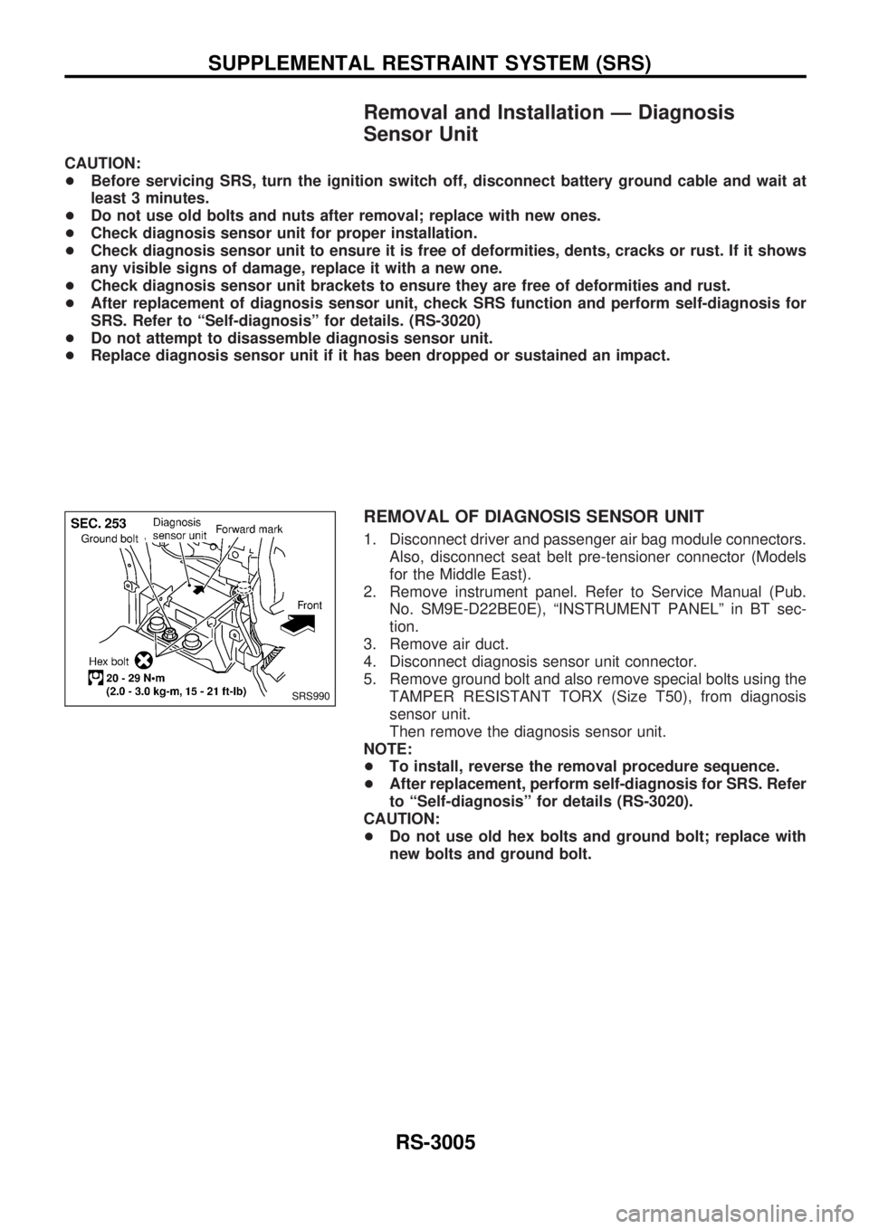
REMOVAL OF DIAGNOSIS SENSOR UNIT
1. Disconnect driver and passenger air bag module connectors.
Also, disconnect seat belt pre-tensioner connector (Models
for the Middle East).
2. Remove instrument panel. Refer to Service Manual (Pub.
No. SM9E-D22BE0E), ªINSTRUMENT PANELº in BT sec-
tion.
3. Remove air duct.
4. Disconnect diagnosis sensor unit connector.
5. Remove ground bolt and also remove special bolts using the
TAMPER RESISTANT TORX (Size T50), from diagnosis
sensor unit.
Then remove the diagnosis sensor unit.
NOTE:
+To install, reverse the removal procedure sequence.
+After replacement, perform self-diagnosis for SRS. Refer
to ªSelf-diagnosisº for details (RS-3020).
CAUTION:
+Do not use old hex bolts and ground bolt; replace with
new bolts and ground bolt.
SRS990
SUPPLEMENTAL RESTRAINT SYSTEM (SRS)
RS-3005