2001 NISSAN PICK-UP ECO mode
[x] Cancel search: ECO modePage 87 of 1306
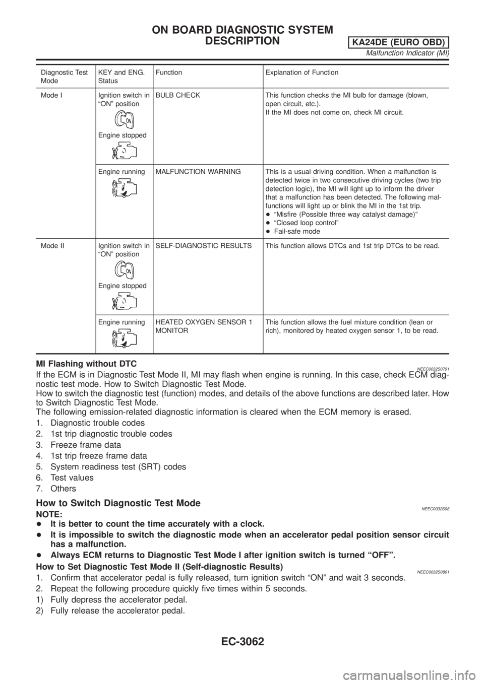
Diagnostic Test
ModeKEY and ENG.
StatusFunction Explanation of Function
Mode I Ignition switch in
ªONº position
Engine stopped
BULB CHECK This function checks the MI bulb for damage (blown,
open circuit, etc.).
If the MI does not come on, check MI circuit.
Engine running
MALFUNCTION WARNING This is a usual driving condition. When a malfunction is
detected twice in two consecutive driving cycles (two trip
detection logic), the MI will light up to inform the driver
that a malfunction has been detected. The following mal-
functions will light up or blink the MI in the 1st trip.
+ªMisfire (Possible three way catalyst damage)º
+ªClosed loop controlº
+Fail-safe mode
Mode II Ignition switch in
ªONº position
Engine stopped
SELF-DIAGNOSTIC RESULTS This function allows DTCs and 1st trip DTCs to be read.
Engine running
HEATED OXYGEN SENSOR 1
MONITORThis function allows the fuel mixture condition (lean or
rich), monitored by heated oxygen sensor 1, to be read.
MI Flashing without DTCNEEC0032S0701If the ECM is in Diagnostic Test Mode II, MI may flash when engine is running. In this case, check ECM diag-
nostic test mode. How to Switch Diagnostic Test Mode.
How to switch the diagnostic test (function) modes, and details of the above functions are described later. How
to Switch Diagnostic Test Mode.
The following emission-related diagnostic information is cleared when the ECM memory is erased.
1. Diagnostic trouble codes
2. 1st trip diagnostic trouble codes
3. Freeze frame data
4. 1st trip freeze frame data
5. System readiness test (SRT) codes
6. Test values
7. Others
How to Switch Diagnostic Test ModeNEEC0032S08NOTE:
+It is better to count the time accurately with a clock.
+It is impossible to switch the diagnostic mode when an accelerator pedal position sensor circuit
has a malfunction.
+Always ECM returns to Diagnostic Test Mode I after ignition switch is turned ªOFFº.
How to Set Diagnostic Test Mode II (Self-diagnostic Results)
NEEC0032S08011. Confirm that accelerator pedal is fully released, turn ignition switch ªONº and wait 3 seconds.
2. Repeat the following procedure quickly five times within 5 seconds.
1) Fully depress the accelerator pedal.
2) Fully release the accelerator pedal.
ON BOARD DIAGNOSTIC SYSTEM
DESCRIPTION
KA24DE (EURO OBD)
Malfunction Indicator (MI)
EC-3062
Page 88 of 1306
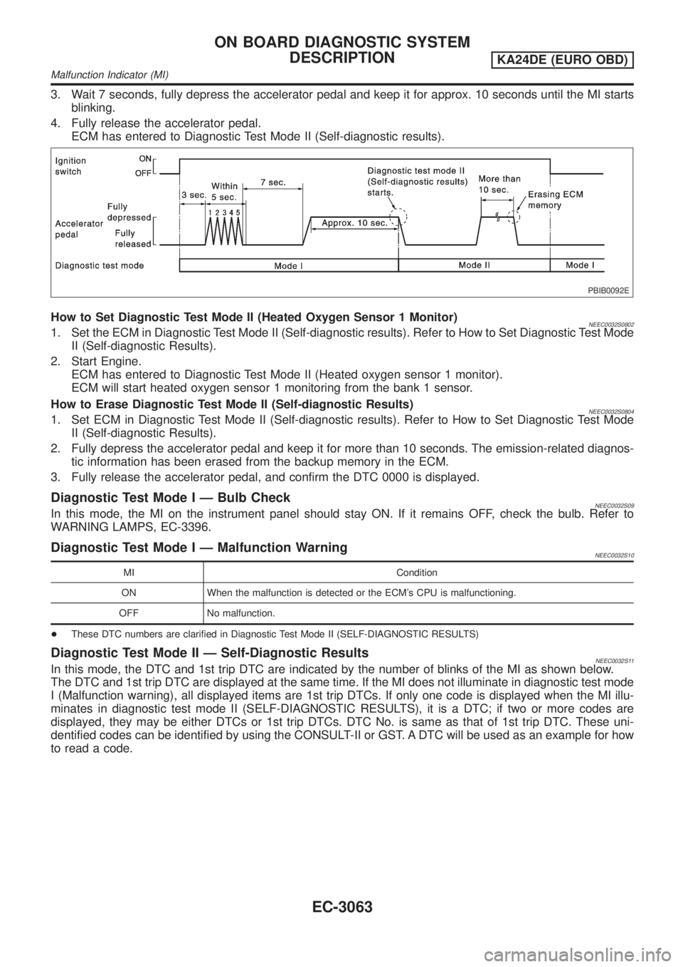
3. Wait 7 seconds, fully depress the accelerator pedal and keep it for approx. 10 seconds until the MI starts
blinking.
4. Fully release the accelerator pedal.
ECM has entered to Diagnostic Test Mode II (Self-diagnostic results).
PBIB0092E
How to Set Diagnostic Test Mode II (Heated Oxygen Sensor 1 Monitor)NEEC0032S08021. Set the ECM in Diagnostic Test Mode II (Self-diagnostic results). Refer to How to Set Diagnostic Test Mode
II (Self-diagnostic Results).
2. Start Engine.
ECM has entered to Diagnostic Test Mode II (Heated oxygen sensor 1 monitor).
ECM will start heated oxygen sensor 1 monitoring from the bank 1 sensor.
How to Erase Diagnostic Test Mode II (Self-diagnostic Results)
NEEC0032S08041. Set ECM in Diagnostic Test Mode II (Self-diagnostic results). Refer to How to Set Diagnostic Test Mode
II (Self-diagnostic Results).
2. Fully depress the accelerator pedal and keep it for more than 10 seconds. The emission-related diagnos-
tic information has been erased from the backup memory in the ECM.
3. Fully release the accelerator pedal, and confirm the DTC 0000 is displayed.
Diagnostic Test Mode I Ð Bulb CheckNEEC0032S09In this mode, the MI on the instrument panel should stay ON. If it remains OFF, check the bulb. Refer to
WARNING LAMPS, EC-3396.
Diagnostic Test Mode I Ð Malfunction WarningNEEC0032S10
MI Condition
ON When the malfunction is detected or the ECM's CPU is malfunctioning.
OFF No malfunction.
+These DTC numbers are clarified in Diagnostic Test Mode II (SELF-DIAGNOSTIC RESULTS)
Diagnostic Test Mode II Ð Self-Diagnostic ResultsNEEC0032S11In this mode, the DTC and 1st trip DTC are indicated by the number of blinks of the MI as shown below.
The DTC and 1st trip DTC are displayed at the same time. If the MI does not illuminate in diagnostic test mode
I (Malfunction warning), all displayed items are 1st trip DTCs. If only one code is displayed when the MI illu-
minates in diagnostic test mode II (SELF-DIAGNOSTIC RESULTS), it is a DTC; if two or more codes are
displayed, they may be either DTCs or 1st trip DTCs. DTC No. is same as that of 1st trip DTC. These uni-
dentified codes can be identified by using the CONSULT-II or GST. A DTC will be used as an example for how
to read a code.
ON BOARD DIAGNOSTIC SYSTEM
DESCRIPTION
KA24DE (EURO OBD)
Malfunction Indicator (MI)
EC-3063
Page 89 of 1306

SEC687C
A particular trouble code can be identified by the number of four-digit numeral flashes. The ªzeroº is indicated
by the number of ten flashes. The length of time the 1,000th-digit numeral flashes on and off is 1.2 seconds
consisting of an ON (0.6-second) - OFF (0.6-second) cycle.
The 100th-digit numeral and lower digit numerals consist of a 0.3-second ON and 0.3-second OFF cycle.
A change from one digit numeral to another occurs at an interval of 1.0-second OFF. In other words, the later
numeral appears on the display 1.3 seconds after the former numeral has disappeared.
A change from one trouble code to another occurs at an interval of 1.8-second OFF.
In this way, all the detected malfunctions are classified by their DTC numbers. The DTC ª0000º refers to no
malfunction. (See ªTROUBLE DIAGNOSIS Ð INDEXº, EC-3009.)
How to Erase Diagnostic Test Mode II (Self-diagnostic Results)
NEEC0032S1101The DTC can be erased from the back up memory in the ECM by depressing accelerator pedal. Refer to How
to Switch Diagnostic Test Mode.
+If the battery is disconnected, the DTC will be lost from the backup memory after approx 24 hours.
+Be careful not to erase the stored memory before starting trouble diagnoses.
Diagnostic Test Mode II Ð Heated Oxygen Sensor 1 MonitorNEEC0032S12In this mode, the MI displays the condition of the fuel mixture (lean or rich) which is monitored by the heated
oxygen sensor 1.
MI Fuel mixture condition in the exhaust gas Air fuel ratio feedback control condition
ON Lean
Closed loop system
OFF Rich
*Remains ON or OFF Any condition Open loop system
*: Maintains conditions just before switching to open loop.
To check the heated oxygen sensor 1 function, start engine in the Diagnostic Test Mode II and warm it up until
engine coolant temperature indicator points to the middle of the gauge.
Next run engine at about 2,000 rpm for about 2 minutes under no-load conditions. Then make sure that the
MI comes ON more than 5 times within 10 seconds with engine running at 2,000 rpm under no-load.
OBD System Operation ChartNEEC0033RELATIONSHIP BETWEEN MI, DTC, 1ST TRIP DTC AND DETECTABLE ITEMSNEEC0033S01+When a malfunction is detected for the first time, the 1st trip DTC and the 1st trip freeze frame data are
stored in the ECM memory.
+When the same malfunction is detected in two consecutive trips, the DTC and the freeze frame data are
stored in the ECM memory, and the MI will come on. For details, refer to ªTwo Trip Detection Logicº on
EC-3049.
ON BOARD DIAGNOSTIC SYSTEM
DESCRIPTION
KA24DE (EURO OBD)
Malfunction Indicator (MI)
EC-3064
Page 90 of 1306
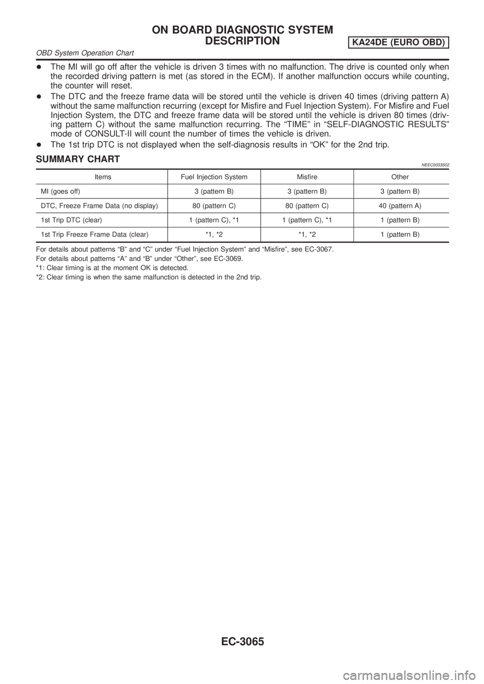
+The MI will go off after the vehicle is driven 3 times with no malfunction. The drive is counted only when
the recorded driving pattern is met (as stored in the ECM). If another malfunction occurs while counting,
the counter will reset.
+The DTC and the freeze frame data will be stored until the vehicle is driven 40 times (driving pattern A)
without the same malfunction recurring (except for Misfire and Fuel Injection System). For Misfire and Fuel
Injection System, the DTC and freeze frame data will be stored until the vehicle is driven 80 times (driv-
ing pattern C) without the same malfunction recurring. The ªTIMEº in ªSELF-DIAGNOSTIC RESULTSº
mode of CONSULT-II will count the number of times the vehicle is driven.
+The 1st trip DTC is not displayed when the self-diagnosis results in ªOKº for the 2nd trip.
SUMMARY CHARTNEEC0033S02
Items Fuel Injection System Misfire Other
MI (goes off) 3 (pattern B) 3 (pattern B) 3 (pattern B)
DTC, Freeze Frame Data (no display) 80 (pattern C) 80 (pattern C) 40 (pattern A)
1st Trip DTC (clear) 1 (pattern C), *1 1 (pattern C), *1 1 (pattern B)
1st Trip Freeze Frame Data (clear) *1, *2 *1, *2 1 (pattern B)
For details about patterns ªBº and ªCº under ªFuel Injection Systemº and ªMisfireº, see EC-3067.
For details about patterns ªAº and ªBº under ªOtherº, see EC-3069.
*1: Clear timing is at the moment OK is detected.
*2: Clear timing is when the same malfunction is detected in the 2nd trip.
ON BOARD DIAGNOSTIC SYSTEM
DESCRIPTION
KA24DE (EURO OBD)
OBD System Operation Chart
EC-3065
Page 99 of 1306
![NISSAN PICK-UP 2001 Repair Manual Freeze frame data
item*Description
INT/A TEMP SE [ÉC]
or [ÉF]+The intake air temperature at the moment a malfunction is detected is displayed.
*: The items are the same as those of 1st trip freeze f NISSAN PICK-UP 2001 Repair Manual Freeze frame data
item*Description
INT/A TEMP SE [ÉC]
or [ÉF]+The intake air temperature at the moment a malfunction is detected is displayed.
*: The items are the same as those of 1st trip freeze f](/manual-img/5/57372/w960_57372-98.png)
Freeze frame data
item*Description
INT/A TEMP SE [ÉC]
or [ÉF]+The intake air temperature at the moment a malfunction is detected is displayed.
*: The items are the same as those of 1st trip freeze frame data.
DATA MONITOR MODENEEC0034S06
Monitored item [Unit]ECM
input
signalsMain
signalsDescription Remarks
ENG SPEED [rpm]jj+Indicates the engine speed computed
from the REF signal (180É signal) of
the camshaft position sensor.+Accuracy becomes poor if engine
speed drops below the idle rpm.
+If the signal is interrupted while the
engine is running, an abnormal value
may be indicated.
MAS A/F SE-B1 [V]jj+The signal voltage of the mass air flow
sensor is displayed.+When the engine is stopped, a cer-
tain value is indicated.
B/FUEL SCHDL [msec]j+ªBase fuel scheduleº indicates the fuel
injection pulse width programmed into
ECM, prior to any learned on board
correction.
A/F ALPHA-B1 [%]j+Indicates the mean value of the air-fuel
ratio feedback correction factor per
cycle.+When the engine is stopped, a cer-
tain value is indicated.
+This data also includes the data for
the air-fuel ratio learning control.
COOLAN TEMP/S
[ÉC] or [ÉF]jj+The engine coolant temperature (deter-
mined by the signal voltage of the
engine coolant temperature sensor) is
displayed.+When the engine coolant temperature
sensor is open or short-circuited,
ECM enters fail-safe mode. The
engine coolant temperature deter-
mined by the ECM is displayed.
HO2S1 (B1) [V]jj+The signal voltage of the heated oxy-
gen sensor 1 is displayed.
HO2S2 (B1) [V]j+The signal voltage of the heated oxy-
gen sensor 2 is displayed.
HO2S1 MNTR (B1)
[RICH/LEAN]jj+Display of heated oxygen sensor 1 sig-
nal during air-fuel ratio feedback con-
trol:
RICH ... means the mixture became
ªrichº, and control is being affected
toward a leaner mixture.
LEAN ... means the mixture became
ªleanº, and control is being affected
toward a rich mixture.+After turning ON the ignition switch,
ªRICHº is displayed until air-fuel mix-
ture ratio feedback control begins.
+When the air-fuel ratio feedback is
clamped, the value just before the
clamping is displayed continuously.
HO2S2 MNTR (B1)
[RICH/LEAN]j+Display of heated oxygen sensor 2 sig-
nal:
RICH ... means the amount of oxygen
after three way catalyst is relatively
small.
LEAN ... means the amount of oxygen
after three way catalyst is relatively
large.+When the engine is stopped, a cer-
tain value is indicated.
VHCL SPEED SE
[km/h] or [mph]jj+The vehicle speed computed from the
vehicle speed sensor signal is dis-
played.
BATTERY VOLT [V]jj+The power supply voltage of ECM is
displayed.
ON BOARD DIAGNOSTIC SYSTEM
DESCRIPTION
KA24DE (EURO OBD)
CONSULT-II
EC-3074
Page 103 of 1306
DTC & SRT CONFIRMATION MODE=NEEC0034S08SRT STATUS ModeNEEC0034S0801For details, refer to ªSYSTEM READINESS TEST (SRT) CODEº,
EC-3051.
SRT Work Support ModeNEEC0034S0803This mode enables a technician to drive a vehicle to set the SRT
while monitoring the SRT status.
DTC Work Support ModeNEEC0034S0802
TEST MODE TEST ITEM CONDITION REFERENCE PAGE
HO2S1HO2S1 (B1) P0133
Refer to corresponding
trouble diagnosis for
DTC.EC-3202
HO2S1 (B1) P0134 EC-3213
HO2S1 (B1) P1143 EC-3310
HO2S1 (B1) P1144 EC-3317
HO2S2HO2S2 (B1) P0139 EC-3227
HO2S2 (B1) P1146 EC-3324
HO2S2 (B1) P1147 EC-3334
REAL TIME DIAGNOSIS IN DATA MONITOR MODE
(RECORDING VEHICLE DATA)
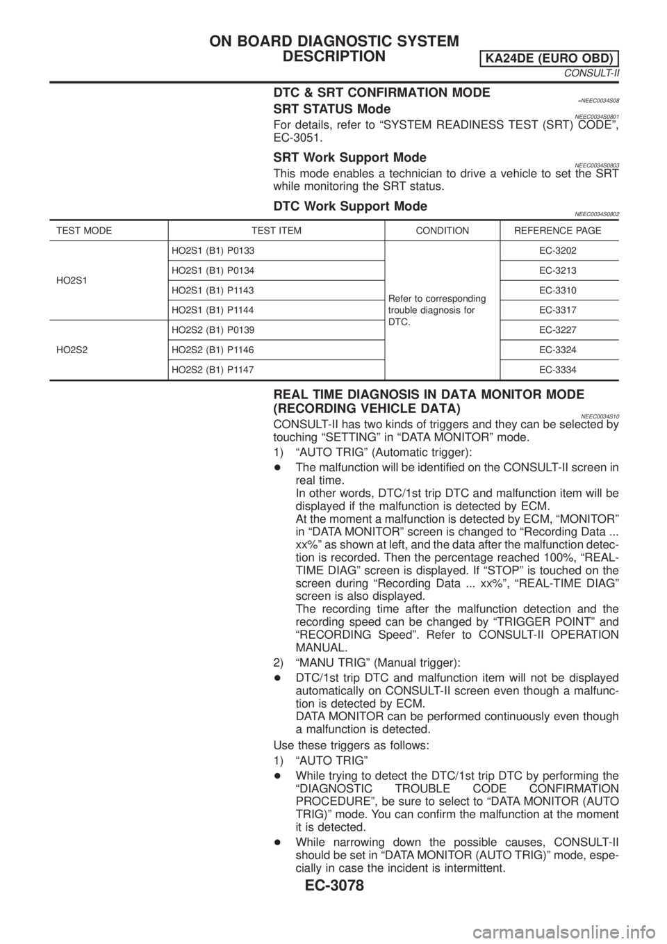
NEEC0034S10CONSULT-II has two kinds of triggers and they can be selected by
touching ªSETTINGº in ªDATA MONITORº mode.
1) ªAUTO TRIGº (Automatic trigger):
+The malfunction will be identified on the CONSULT-II screen in
real time.
In other words, DTC/1st trip DTC and malfunction item will be
displayed if the malfunction is detected by ECM.
At the moment a malfunction is detected by ECM, ªMONITORº
in ªDATA MONITORº screen is changed to ªRecording Data ...
xx%º as shown at left, and the data after the malfunction detec-
tion is recorded. Then the percentage reached 100%, ªREAL-
TIME DIAGº screen is displayed. If ªSTOPº is touched on the
screen during ªRecording Data ... xx%º, ªREAL-TIME DIAGº
screen is also displayed.
The recording time after the malfunction detection and the
recording speed can be changed by ªTRIGGER POINTº and
ªRECORDING Speedº. Refer to CONSULT-II OPERATION
MANUAL.
2) ªMANU TRIGº (Manual trigger):
+DTC/1st trip DTC and malfunction item will not be displayed
automatically on CONSULT-II screen even though a malfunc-
tion is detected by ECM.
DATA MONITOR can be performed continuously even though
a malfunction is detected.
Use these triggers as follows:
1) ªAUTO TRIGº
+While trying to detect the DTC/1st trip DTC by performing the
ªDIAGNOSTIC TROUBLE CODE CONFIRMATION
PROCEDUREº, be sure to select to ªDATA MONITOR (AUTO
TRIG)º mode. You can confirm the malfunction at the moment
it is detected.
+While narrowing down the possible causes, CONSULT-II
should be set in ªDATA MONITOR (AUTO TRIG)º mode, espe-
cially in case the incident is intermittent.
ON BOARD DIAGNOSTIC SYSTEM
DESCRIPTION
KA24DE (EURO OBD)
CONSULT-II
EC-3078
Page 112 of 1306
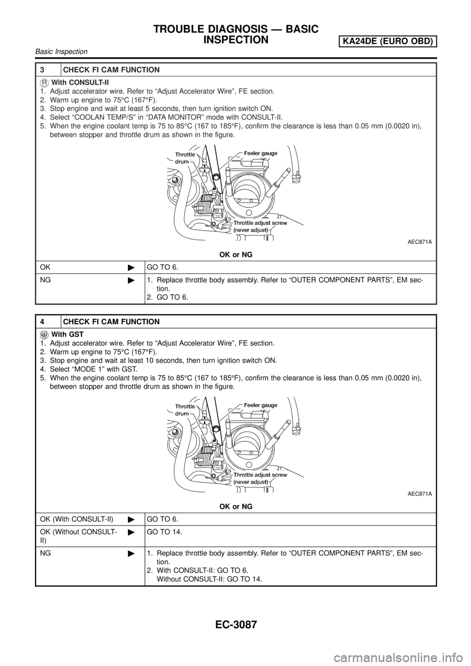
3 CHECK FI CAM FUNCTION
With CONSULT-II
1. Adjust accelerator wire. Refer to ªAdjust Accelerator Wireº, FE section.
2. Warm up engine to 75ÉC (167ÉF).
3. Stop engine and wait at least 5 seconds, then turn ignition switch ON.
4. Select ªCOOLAN TEMP/Sº in ªDATA MONITORº mode with CONSULT-II.
5. When the engine coolant temp is 75 to 85ÉC (167 to 185ÉF), confirm the clearance is less than 0.05 mm (0.0020 in),
between stopper and throttle drum as shown in the figure.
AEC871A
OK or NG
OK©GO TO 6.
NG©1. Replace throttle body assembly. Refer to ªOUTER COMPONENT PARTSº, EM sec-
tion.
2. GO TO 6.
4 CHECK FI CAM FUNCTION
With GST
1. Adjust accelerator wire. Refer to ªAdjust Accelerator Wireº, FE section.
2. Warm up engine to 75ÉC (167ÉF).
3. Stop engine and wait at least 10 seconds, then turn ignition switch ON.
4. Select ªMODE 1º with GST.
5. When the engine coolant temp is 75 to 85ÉC (167 to 185ÉF), confirm the clearance is less than 0.05 mm (0.0020 in),
between stopper and throttle drum as shown in the figure.
AEC871A
OK or NG
OK (With CONSULT-II)©GO TO 6.
OK (Without CONSULT-
II)©GO TO 14.
NG©1. Replace throttle body assembly. Refer to ªOUTER COMPONENT PARTSº, EM sec-
tion.
2. With CONSULT-II: GO TO 6.
Without CONSULT-II: GO TO 14.
TROUBLE DIAGNOSIS Ð BASIC
INSPECTION
KA24DE (EURO OBD)
Basic Inspection
EC-3087
Page 119 of 1306
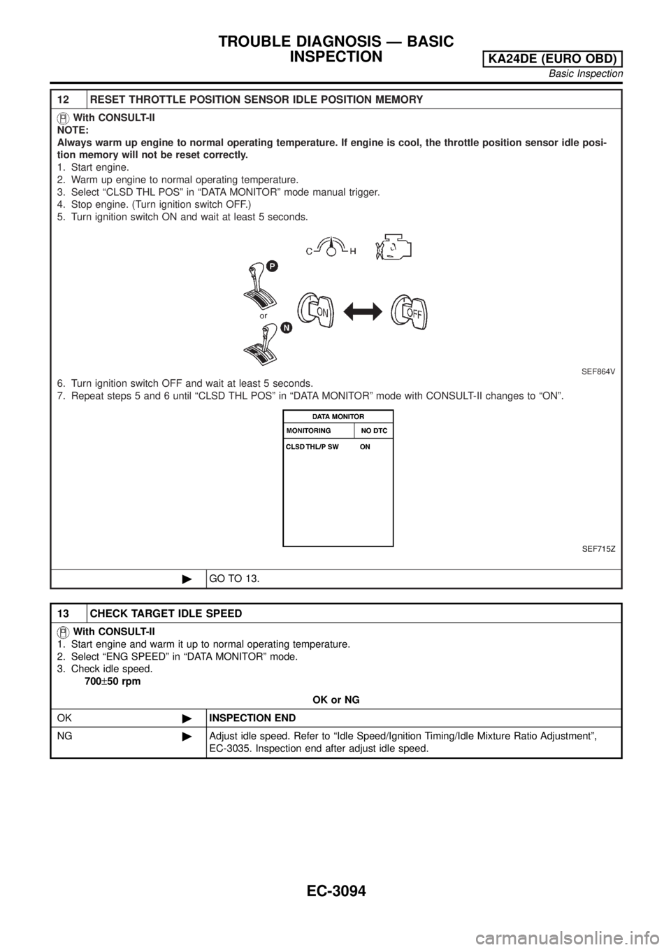
12 RESET THROTTLE POSITION SENSOR IDLE POSITION MEMORY
With CONSULT-II
NOTE:
Always warm up engine to normal operating temperature. If engine is cool, the throttle position sensor idle posi-
tion memory will not be reset correctly.
1. Start engine.
2. Warm up engine to normal operating temperature.
3. Select ªCLSD THL POSº in ªDATA MONITORº mode manual trigger.
4. Stop engine. (Turn ignition switch OFF.)
5. Turn ignition switch ON and wait at least 5 seconds.
SEF864V
6. Turn ignition switch OFF and wait at least 5 seconds.
7. Repeat steps 5 and 6 until ªCLSD THL POSº in ªDATA MONITORº mode with CONSULT-II changes to ªONº.
SEF715Z
©GO TO 13.
13 CHECK TARGET IDLE SPEED
With CONSULT-II
1. Start engine and warm it up to normal operating temperature.
2. Select ªENG SPEEDº in ªDATA MONITORº mode.
3. Check idle speed.
700±50 rpm
OK or NG
OK©INSPECTION END
NG©Adjust idle speed. Refer to ªIdle Speed/Ignition Timing/Idle Mixture Ratio Adjustmentº,
EC-3035. Inspection end after adjust idle speed.
TROUBLE DIAGNOSIS Ð BASIC
INSPECTION
KA24DE (EURO OBD)
Basic Inspection
EC-3094