Page 27 of 3051
SAT228K
WORK SUPPORT MODE WITH CONSULT-IINLAT0022S081. Turn ignition switch ªOFFº.
2. Connect CONSULT-II to data link connector which is located
in the left side lower dash panel.
3. Turn ignition switch ªONº.
SAT586J
4. Touch ªSTARTº.
SAT250K
5. Touch ªCVTº.
SAT252K
6. Touch ªWORK SUPPORTº.
SAT933J
7. Touch ªENGINE BRAKE ADJUSTMENTº.
8. Touch ªSTARTº.
ON BOARD DIAGNOSTIC SYSTEM DESCRIPTIONEURO-OBD
CONSULT-II (Cont'd)
AT-26
Page 56 of 3051
SAT228K
CONSULT-II Setting ProcedureNLAT0028S04021. Turn ignition switch ªOFFº.
2. Connect CONSULT-II to data link connector which is located
in the left side lower dash panel.
SAT586J
3. Turn ignition switch ªONº.
4. Touch ªSTARTº.
SAT250K
5. Touch ªCVTº.
SAT252K
6. Touch ªDATA MONITORº.
SAT253K
7. Touch ªMAIN SIGNALSº to set recording condition.
8. See ªNumerical Displayº, ªBarchart Displayº or ªLine Graph
Displayº.
9. Touch ªSTARTº.
TROUBLE DIAGNOSIS Ð BASIC INSPECTION
Road Test (Cont'd)
AT-55
Page 254 of 3051
InstallationNLBR0026CAUTION:
+Be careful not to deform or bend brake pipes, during
booster installation.
+Replace clevis pin if damaged.
+Refill with new brake fluid“DOT 4”.
+Never reuse drained brake fluid.
+Take care not to damage brake booster mounting bolt
thread during installation. Due to the acute angle of
installation, the threads can be damaged with the dash
panel.
SBR237EA
1. Before fitting booster, temporarily adjust clevis to dimension
shown.
2. Fit booster, then secure mounting nuts (brake pedal bracket to
master cylinder) lightly.
3. Connect brake pedal and booster input rod with clevis pin.
4. Secure mounting nuts.
Specification:
13-16N·m (1.3 - 1.6 kg-m,9-12ft-lb)
5. Install master cylinder. Refer to“Installation”in“MASTER
CYLINDER”, BR-15.
6. Bleed air. Refer to“Bleeding Brake System”, BR-8 and“Air
Bleeding Procedure”, CL-10.
BRAKE BOOSTER
Installation
BR-17
Page 330 of 3051

General SpecificationsNLBR0077Unit: mm (in)
EngineQG18DE, SR20DE YD22DDTi
Front BrakeBrake model CL25VCG
Cylinder bore diameter 57.2 (2.2529)
Pad
Length×width×thickness110.6×54.2×11.0 (4.35×2.13×0.433)
Rotor outer
diameter×thickness280×28 (11.02×1.10)
Rear BrakeBrake model CL11HDG (disc brake)
Cylinder bore diam-
eterCam & Strut type 38 (1.496)
Ball & Ramp type 38.2 (1.504)
Pad
Length×width×thickness79.8×38.5×9.3 (3.142×1.516×0.37)
Rotor outer diameter×thickness 278×10 (10.94×0.39)
Master cylinder Cylinder bore diameter 23.81 (15/16)
Brake boosterBooster model S255 M215T S255
DiaphragmPrimary 255 (10.04) 230 (9.06) 255 (10.04)
Secondary—205 (8.07)—
Specified brake fluidDOT 4
Disc BrakeNLBR0078Unit: mm (in)
Brake modelCL25VCG CL11HDG
Pad wear limit Minimum thickness 2.0 (0.078) 2.0 (0.079)
Rotor repair limitMaximum runout 0.07 (0.0028) 0.07 (0.0028)
Minimum thickness 26.0 (1.024) 9 (0.35)
Brake PedalNLBR0079Unit: mm (in)
Free height“H”*LHDM/T 154.8 - 164.8 (6.09 - 6.49)
CVT 164 - 174 (6.46 - 6.85)
RHDM/T 154.8 - 164.8 (6.09 - 6.49)
CVT 164 - 174 (6.46 - 6.85)
Clearance“C”between pedal stopper and threaded end of stop lamp switch or brake switch 0.75 - 2.00 (0.0295 - 0.0787)
*: Measured from surface of dash panel to surface of pedal pad
Parking BrakeNLBR0080
TypeCenter lever
Number of notches
[under force of 196 N (20 kg, 44 lb)]5-6
Number of notches
when warning lamp switch comes on1
SERVICE DATA AND SPECIFICATIONS (SDS)
General Specifications
BR-93
Page 359 of 3051

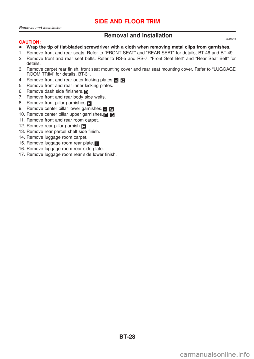
Removal and InstallationNLBT0013CAUTION:
+Wrap the tip of flat-bladed screwdriver with a cloth when removing metal clips from garnishes.
1. Remove front and rear seats. Refer to ªFRONT SEATº and ªREAR SEATº for details, BT-46 and BT-49.
2. Remove front and rear seat belts. Refer to RS-5 and RS-7, ªFront Seat Beltº and ªRear Seat Beltº for
details.
3. Remove carpet rear finish, front seat mounting cover and rear seat mounting cover. Refer to ªLUGGAGE
ROOM TRIMº for details, BT-31.
4. Remove front and rear outer kicking plates.
5. Remove front and rear inner kicking plates.
6. Remove dash side finishers.
7. Remove front and rear body side welts.
8. Remove front pillar garnishes.
9. Remove center pillar lower garnishes.
10. Remove center pillar upper garnishes.
11. Remove front and rear room carpet.
12. Remove rear pillar garnish.
13. Remove rear parcel shelf side finish.
14. Remove luggage room carpet.
15. Remove luggage room rear plate.
16. Remove luggage room rear side plate.
17. Remove luggage room rear side lower finish.
SIDE AND FLOOR TRIM
Removal and Installation
BT-28
Page 507 of 3051
SEF094Y
CONSULT-II=NLEC0034CONSULT-II INSPECTION PROCEDURENLEC0034S011. Turn ignition switch OFF.
2. Connect ªCONSULT-IIº to data link connector.
(Data link connector is located under lower dash panel near
the fuse box cover.)
PBR455D
3. Turn ignition switch ON.
4. Touch ªSTARTº.
SEF995X
5. Touch ªENGINEº.
SEF824Y
6. Perform each diagnostic test mode according to each service
procedure.
For further information, see the CONSULT-II Operation
Manual.
ON BOARD DIAGNOSTIC SYSTEM DESCRIPTIONQG18DE
CONSULT-II
EC-82
Page 518 of 3051
SEF139P
Generic Scan Tool (GST)=NLEC0035DESCRIPTIONNLEC0035S01Generic Scan Tool (OBDII scan tool) complying with ISO15031-4
has 9 different functions explained on the next page.
ISO9141 is used as the protocol.
The name ªGSTº or ªGeneric Scan Toolº is used in this service
manual.
SEF094Y
GST INSPECTION PROCEDURENLEC0035S021. Turn ignition switch OFF.
2. Connect ªGSTº to data link connector. (Data link connector is
located under lower dash panel near the fuse box cover.)
SEF398S
3. Turn ignition switch ON.
4. Enter the program according to instruction on the screen or in
the operation manual.
(*: Regarding GST screens in this section, sample screens are
shown.)
SEF416S
5. Perform each diagnostic mode according to each service pro-
cedure.
For further information, see the GST Operation Manual of the
tool maker.
ON BOARD DIAGNOSTIC SYSTEM DESCRIPTIONQG18DE
Generic Scan Tool (GST)
EC-93
Page 1032 of 3051
SEF094Y
CONSULT-II=NLEC1365CONSULT-II INSPECTION PROCEDURENLEC1365S011. Turn ignition switch OFF.
2. Connect ªCONSULT-IIº to data link connector which is located
under lower dash panel near the fuse box cover.
PBR455D
3. Turn ignition switch ON.
4. Touch ªSTARTº.
SEF995X
5. Touch ªENGINEº.
SEF824Y
6. Perform each diagnostic test mode according to each service
procedure.
For further information, see the CONSULT-II Operation
Manual.
ON BOARD DIAGNOSTIC SYSTEM DESCRIPTIONSR20DE
CONSULT-II
EC-607