Page 1042 of 3051
SEF139P
Generic Scan Tool (GST)=NLEC1366DESCRIPTIONNLEC1366S01Generic Scan Tool (OBDII scan tool) complying with ISO 15031-4
has 9 different functions explained on the next page.
ISO 9141 is used as the protocol.
The name ªGSTº or ªGeneric Scan Toolº is used in this service
manual.
SEF094Y
GST INSPECTION PROCEDURENLEC1366S021. Turn ignition switch OFF.
2. Connect ªGSTº to data link connector which is located under
lower dash panel near the fuse box cover.
SEF398S
3. Turn ignition switch ON.
4. Enter the program according to instruction on the screen or in
the operation manual.
(*: Regarding GST screens in this section, sample screens are
shown.)
SEF416S
5. Perform each diagnostic mode according to each service pro-
cedure.
For further information, see the GST Operation Manual of the
tool maker.
ON BOARD DIAGNOSTIC SYSTEM DESCRIPTIONSR20DE
Generic Scan Tool (GST)
EC-617
Page 1519 of 3051

Fuel Filter
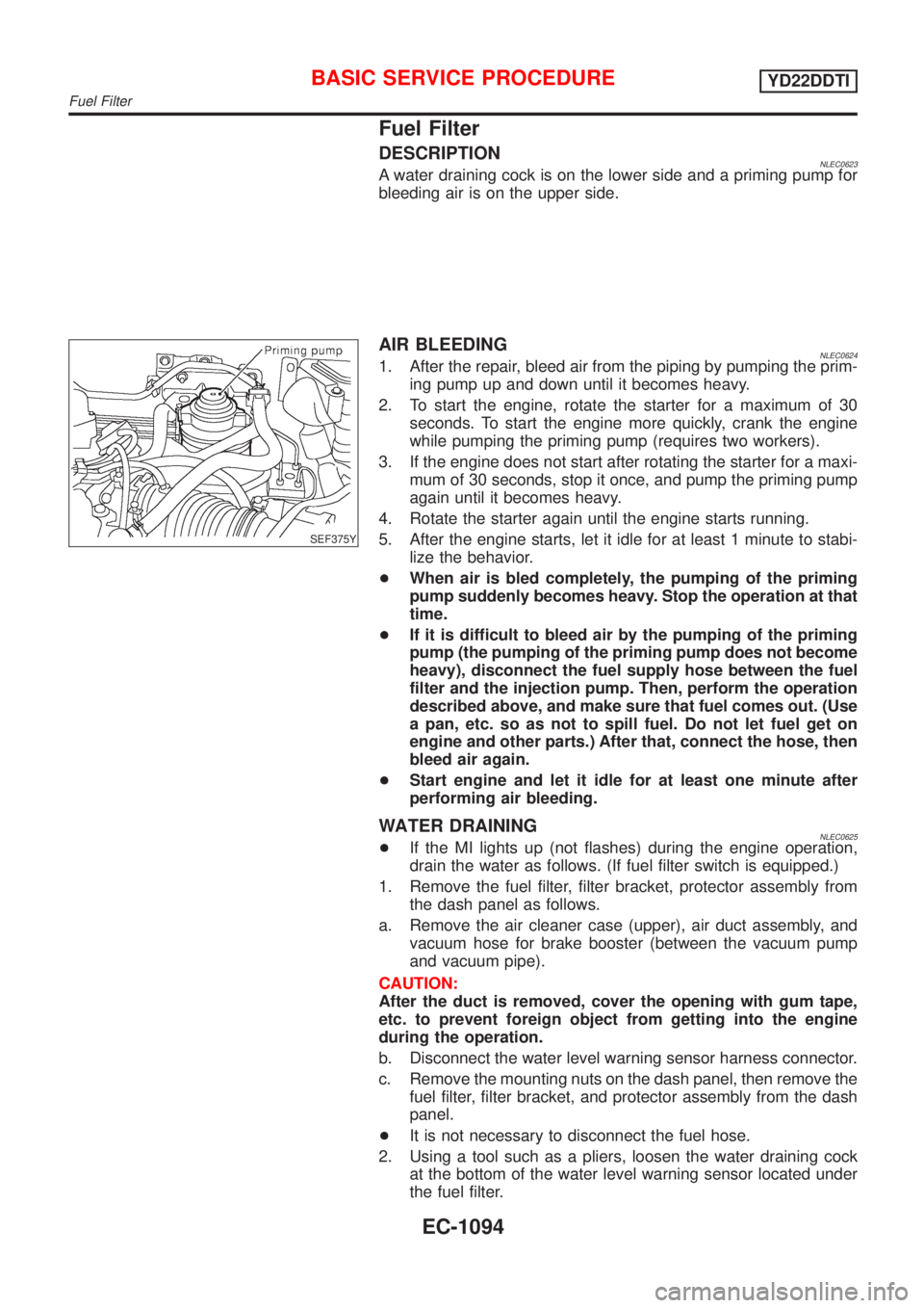
DESCRIPTIONNLEC0623A water draining cock is on the lower side and a priming pump for
bleeding air is on the upper side.
SEF375Y
AIR BLEEDINGNLEC06241. After the repair, bleed air from the piping by pumping the prim-
ing pump up and down until it becomes heavy.
2. To start the engine, rotate the starter for a maximum of 30
seconds. To start the engine more quickly, crank the engine
while pumping the priming pump (requires two workers).
3. If the engine does not start after rotating the starter for a maxi-
mum of 30 seconds, stop it once, and pump the priming pump
again until it becomes heavy.
4. Rotate the starter again until the engine starts running.
5. After the engine starts, let it idle for at least 1 minute to stabi-
lize the behavior.
+When air is bled completely, the pumping of the priming
pump suddenly becomes heavy. Stop the operation at that
time.
+If it is difficult to bleed air by the pumping of the priming
pump (the pumping of the priming pump does not become
heavy), disconnect the fuel supply hose between the fuel
filter and the injection pump. Then, perform the operation
described above, and make sure that fuel comes out. (Use
a pan, etc. so as not to spill fuel. Do not let fuel get on
engine and other parts.) After that, connect the hose, then
bleed air again.
+Start engine and let it idle for at least one minute after
performing air bleeding.
WATER DRAININGNLEC0625+If the MI lights up (not flashes) during the engine operation,
drain the water as follows. (If fuel filter switch is equipped.)
1. Remove the fuel filter, filter bracket, protector assembly from
the dash panel as follows.
a. Remove the air cleaner case (upper), air duct assembly, and
vacuum hose for brake booster (between the vacuum pump
and vacuum pipe).
CAUTION:
After the duct is removed, cover the opening with gum tape,
etc. to prevent foreign object from getting into the engine
during the operation.
b. Disconnect the water level warning sensor harness connector.
c. Remove the mounting nuts on the dash panel, then remove the
fuel filter, filter bracket, and protector assembly from the dash
panel.
+It is not necessary to disconnect the fuel hose.
2. Using a tool such as a pliers, loosen the water draining cock
at the bottom of the water level warning sensor located under
the fuel filter.
BASIC SERVICE PROCEDUREYD22DDTI
Fuel Filter
EC-1094
Page 1527 of 3051
SEF378Y
CONSULT-IINLEC0629CONSULT-II INSPECTION PROCEDURENLEC0629S011. Turn ignition switch OFF.
2. Connect CONSULT-II to data link connector.
(Data link connector is located under the driver side dash
panel.)
SEF995X
SEF320Y
3. Turn ignition switch ON.
4. Touch ªSTARTº.
5. Touch ªENGINEº.
6. Perform each diagnostic test mode according to each service
procedure.
For further information, see the CONSULT-II Operation
Manual.
ON BOARD DIAGNOSTIC SYSTEM DESCRIPTIONYD22DDTI
CONSULT-II
EC-1102
Page 1863 of 3051
Combination MeterNLEL0443CHECKNLEL0443S01Models with NATS security indicator on dash boardNLEL0443S0105
YEL990B
METERS AND GAUGES
Combination Meter
EL-132
Page 1865 of 3051
SchematicNLEL0444MODELS WITH NATS SECURITY INDICATOR ON DASH
BOARD
NLEL0444S02
YEL991B
METERS AND GAUGES
Schematic
EL-134
Page 2067 of 3051
SchematicNLEL0509MODELS WITH NATS SECURITY INDICATOR ON DASH
BOARD
NLEL0509S02
YEL951B
NATS (NISSAN ANTI-THEFT SYSTEM)
Schematic
EL-336
Page 2069 of 3051
Wiring Diagram Ð NATS ÐNLEL0409MODELS WITH NATS SECURITY INDICATOR ON DASH BOARDNLEL0409S04LHD ModelsNLEL0409S0401
YEL952B
NATS (NISSAN ANTI-THEFT SYSTEM)
Wiring Diagram Ð NATS Ð
EL-338
Page 2092 of 3051

DIAGNOSTIC PROCEDURE 6 (MODELS WITH NATS
SECURITY INDICATOR ON DASH BOARD)
=NLEL0411S10ªSECURITY INDICATOR LAMP DOES NOT LIGHT UPº
1 CHECK FUSE
Check 10A fuse [No. 12, located in the fuse block (J/B)].
Is 10A fuse OK?
Ye s©GO TO 2.
No©Replace fuse.
2 CHECK SECURITY INDICATOR LAMP
1. Install 10A fuse.
2. Perform initialization with CONSULT-II.
For initialization, refer to ªCONSULT-II Operation Manual NATSº.
3. Turn ignition switch OFF.
4. Start engine and turn ignition switch OFF.
5. Check the security indicator lamp lighting.
Security indicator lamp should be light up.
OK or NG
OK©INSPECTION END
NG©GO TO 3.
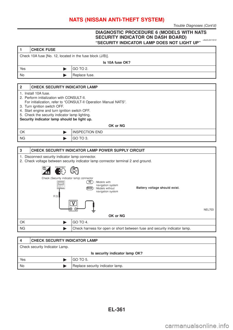
3 CHECK SECURITY INDICATOR LAMP POWER SUPPLY CIRCUIT
1. Disconnect security indicator lamp connector.
2. Check voltage between security indicator lamp connector terminal 2 and ground.
NEL703
OK or NG
OK©GO TO 4.
NG©Check harness for open or short between fuse and security indicator lamp.
4 CHECK SECURITY INDICATOR LAMP
Check security Indicator Lamp.
Is security indicator lamp OK?
Ye s©GO TO 5.
No©Replace security indicator lamp.
NATS (NISSAN ANTI-THEFT SYSTEM)
Trouble Diagnoses (Cont'd)
EL-361