Page 2872 of 3051

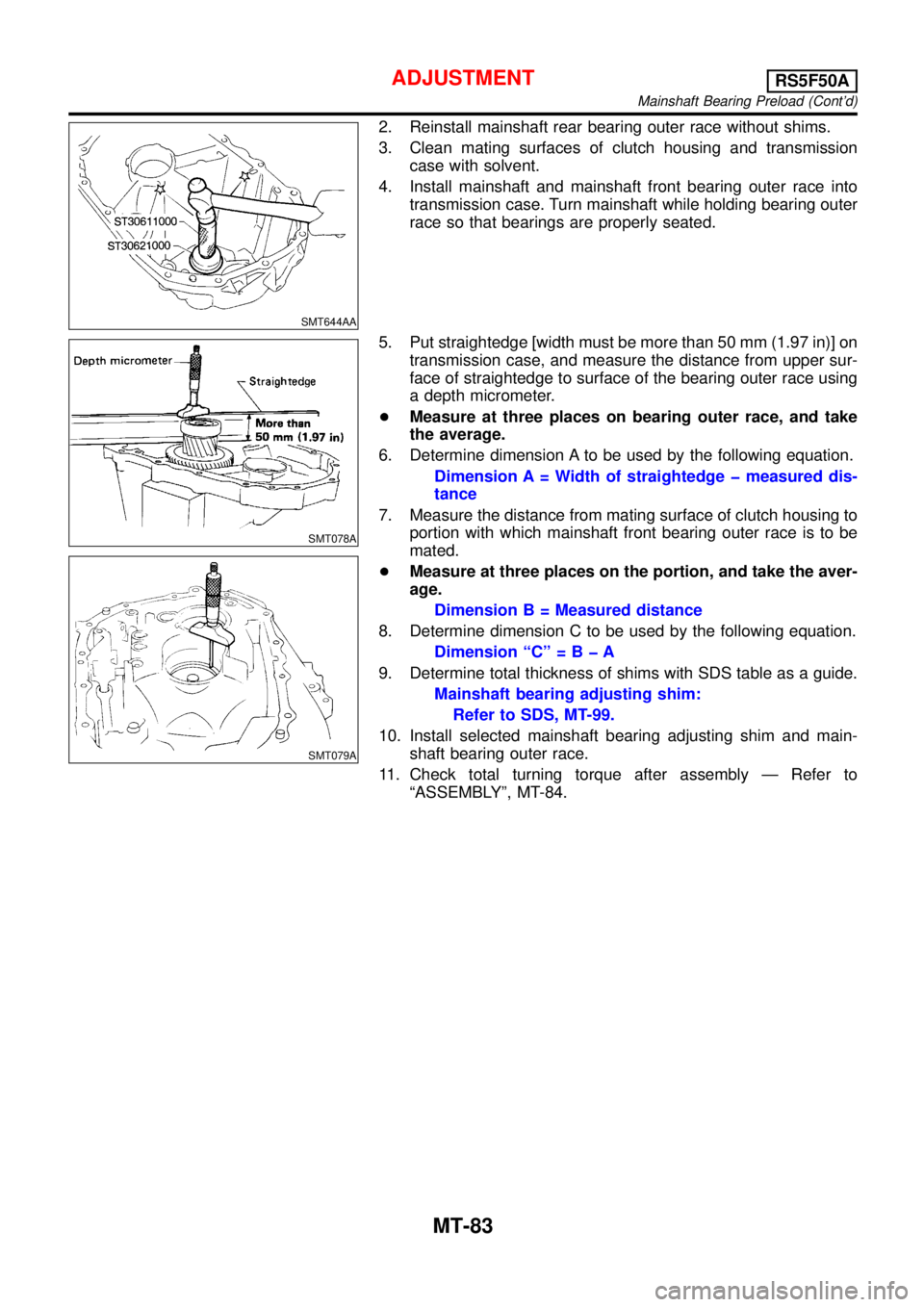
SMT644AA
2. Reinstall mainshaft rear bearing outer race without shims.
3. Clean mating surfaces of clutch housing and transmission
case with solvent.
4. Install mainshaft and mainshaft front bearing outer race into
transmission case. Turn mainshaft while holding bearing outer
race so that bearings are properly seated.
SMT078A
SMT079A
5. Put straightedge [width must be more than 50 mm (1.97 in)] on
transmission case, and measure the distance from upper sur-
face of straightedge to surface of the bearing outer race using
a depth micrometer.
+Measure at three places on bearing outer race, and take
the average.
6. Determine dimension A to be used by the following equation.
Dimension A = Width of straightedge � measured dis-
tance
7. Measure the distance from mating surface of clutch housing to
portion with which mainshaft front bearing outer race is to be
mated.
+Measure at three places on the portion, and take the aver-
age.
Dimension B = Measured distance
8. Determine dimension C to be used by the following equation.
Dimension “C”=B�A
9. Determine total thickness of shims with SDS table as a guide.
Mainshaft bearing adjusting shim:
Refer to SDS, MT-99.
10. Install selected mainshaft bearing adjusting shim and main-
shaft bearing outer race.
11. Check total turning torque after assembly—Refer to
“ASSEMBLY”, MT-84.
ADJUSTMENTRS5F50A
Mainshaft Bearing Preload (Cont’d)
MT-83
Page 2876 of 3051
SMT070A
17. Place magnet on clutch housing.
SMT446C
18. If bearing preload of mainshaft was adjusted, install selected
shim(s) into transmission case.
+To aid in installation of transmission case, place shift
selector in the 1st and 2nd shift bracket or between 1st
and 2nd bracket and 3rd and 4th bracket.
19. Apply sealant to mating surface of transmission case and
install it. Refer to“Case Components”, MT-62.
20. Install PNP switch.
SMT626D
21. Apply sealant to threads of check plugs. Install balls, springs
and plugs. Refer to“Shift Control Components”, MT-64.
22. After assembly, check that you can shift into each gear
smoothly.
SAT478EA
23. Measure total turning torque.
Total turning torque (New bearing):
8.8 - 21.6 N·m (90 - 220 kg-cm, 78 - 191 in-lb)
+When old bearing is used again, preload will be slightly
less than the above. Make sure torque is close to the
specified range.
ASSEMBLYRS5F50A
MT-87
Page 3046 of 3051

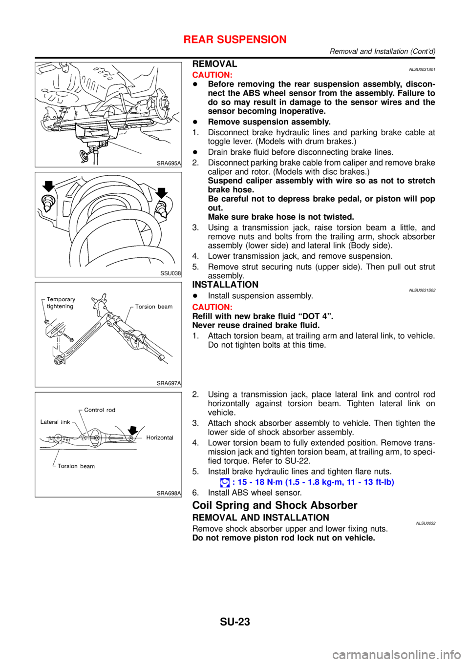
SRA695A
SSU038
REMOVALNLSU0031S01CAUTION:
+Before removing the rear suspension assembly, discon-
nect the ABS wheel sensor from the assembly. Failure to
do so may result in damage to the sensor wires and the
sensor becoming inoperative.
+Remove suspension assembly.
1. Disconnect brake hydraulic lines and parking brake cable at
toggle lever. (Models with drum brakes.)
+Drain brake fluid before disconnecting brake lines.
2. Disconnect parking brake cable from caliper and remove brake
caliper and rotor. (Models with disc brakes.)
Suspend caliper assembly with wire so as not to stretch
brake hose.
Be careful not to depress brake pedal, or piston will pop
out.
Make sure brake hose is not twisted.
3. Using a transmission jack, raise torsion beam a little, and
remove nuts and bolts from the trailing arm, shock absorber
assembly (lower side) and lateral link (Body side).
4. Lower transmission jack, and remove suspension.
5. Remove strut securing nuts (upper side). Then pull out strut
assembly.
SRA697A
INSTALLATIONNLSU0031S02+Install suspension assembly.
CAUTION:
Refill with new brake fluid“DOT 4”.
Never reuse drained brake fluid.
1. Attach torsion beam, at trailing arm and lateral link, to vehicle.
Do not tighten bolts at this time.
SRA698A
2. Using a transmission jack, place lateral link and control rod
horizontally against torsion beam. Tighten lateral link on
vehicle.
3. Attach shock absorber assembly to vehicle. Then tighten the
lower side of shock absorber assembly.
4. Lower torsion beam to fully extended position. Remove trans-
mission jack and tighten torsion beam, at trailing arm, to speci-
fied torque. Refer to SU-22.
5. Install brake hydraulic lines and tighten flare nuts.
:15-18N·m (1.5 - 1.8 kg-m, 11 - 13 ft-lb)
6. Install ABS wheel sensor.
Coil Spring and Shock Absorber
REMOVAL AND INSTALLATIONNLSU0032Remove shock absorber upper and lower fixing nuts.
Do not remove piston rod lock nut on vehicle.
REAR SUSPENSION
Removal and Installation (Cont’d)
SU-23