Page 1439 of 3051
Diagnostic ProcedureNLEC1846
1 CHECK OVERALL FUNCTION
1. Start engine and warm it up to normal operating temperature.
2. Check the voltage between ECM terminals 10, 19, 54, 55, 56 and ground.
SEF791Z
OK or NG
OK©INSPECTION END
NG©GO TO 2.
2 CHECK A/T CONTROL INPUT SIGNAL CIRCUIT FOR OPEN
1. Turn ignition switch ªOFFº.
2. Disconnect ECM harness connector and TCM (Transmission Control Module) harness connector.
SEF116Y
3. Check harness continuity between the following terminals.
MTBL0574
Refer to Wiring Diagram.
Continuity should exist.
OK or NG
OK©GO TO 3.
NG©Repair harness or connectors.
A/T COMMUNICATION LINESR20DE
Diagnostic Procedure
EC-1014
Page 1878 of 3051
INSPECTION/VEHICLE SPEED SENSOR=NLEL0448S04
1 CHECK VEHICLE SPEED SENSOR OUTPUT
1. Remove vehicle speed sensor from transmission.
2. Check voltage between combination meter terminal 18 and ground while quickly turning speed sensor pinion.
NEL658
OK or NG
OK©Vehicle speed sensor is OK.
NG©GO TO 2.
2 CHECK VEHICLE SPEED SENSOR
Check resistance between vehicle speed sensor terminals 1 and 2.
NEL659
OK or NG
OK©Check the following.
+Harness between combination meter and vehicle speed sensor
+Vehicle speed sensor ground circuit
NG©Replace vehicle speed sensor.
METERS AND GAUGES
Trouble Diagnoses (Cont'd)
EL-147
Page 1884 of 3051
SEL498X
Electrical Components Inspection=NLEL0449FUEL LEVEL SENSOR UNIT CHECKNLEL0449S02+For removal, refer to FE-6, FE-19 ªFUEL SYSTEMº.
Check the resistance between terminals 4 and 1.
Ohmmeter
Float position mm (in)Resistance
valueW
(+) (þ)
41*1 Full139.5 - 145.5
(5.49 - 5.73)Approx.4-6
*2 1/286.7 - 90.7 (3.41
- 3.57)32-33
*3 Empty10.1 - 12.1 (0.40
- 0.48)80-83
*1 and *3: When float rod is in contact with stopper.
MEL424F
THERMAL TRANSMITTER CHECKNLEL0449S03Check the resistance between the terminals of thermal transmitter
and body ground.
Water temperature Resistance
65ÉC (149ÉF) Approx. 1,179 - 1,417W
91ÉC (196ÉF) Approx. 474 - 568W
CEL219AA
VEHICLE SPEED SENSOR SIGNAL CHECKNLEL0449S041. Remove vehicle speed sensor from transmission.
2. Turn vehicle speed sensor pinion quickly and measure voltage
across 1 and 2.
METERS AND GAUGES
Electrical Components Inspection
EL-153
Page 2137 of 3051

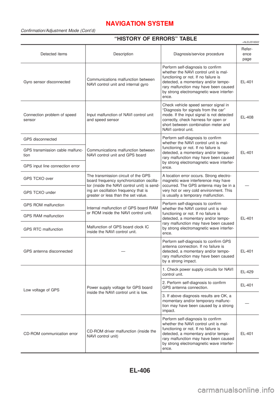
ªHISTORY OF ERRORSº TABLE=NLEL0516S02
Detected items Description Diagnosis/service procedureRefer-
ence
page
Gyro sensor disconnectedCommunications malfunction between
NAVI control unit and internal gyroPerform self-diagnosis to confirm
whether the NAVI control unit is mal-
functioning or not. If no failure is
detected, a momentary and/or tempo-
rary malfunction may have been caused
by strong electromagnetic wave interfer-
ence.EL-401
Connection problem of speed
sensorInput malfunction of NAVI control unit
and speed sensorCheck vehicle speed sensor signal in
ªDiagnosis for signals from the carº
mode. If the input signal is not detected
correctly, check harness for open or
short between combination meter and
NAVI control unit.EL-408
GPS disconnected
Communications malfunction between
NAVI control unit and GPS boardPerform self-diagnosis to confirm
whether the NAVI control unit is mal-
functioning or not. If no failure is
detected, a momentary and/or tempo-
rary malfunction may have been caused
by strong electromagnetic wave interfer-
ence.EL-401 GPS transmission cable malfunc-
tion
GPS input line connection error
GPS TCXO overThe transmission circuit of the GPS
board frequency synchronization oscilla-
tor (inside the NAVI control unit) is send-
ing an oscillation frequency that is
greater or less than the set value.A location error occurs. Strong electro-
magnetic wave interference may have
occurred. The GPS antenna may be in a
very hot or very cold environment. This
is usually a temporary malfunction.Ð
GPS TCXO under
GPS ROM malfunction
Internal malfunction of GPS board RAM
or ROM inside the NAVI control unit.Perform self-diagnosis to confirm
whether the NAVI control unit is mal-
functioning or not. If no failure is
detected, a momentary and/or tempo-
rary malfunction may have been caused
by strong electromagnetic wave interfer-
ence.EL-401 GPS RAM malfunction
GPS RTC malfunctionMalfunction of GPS board clock IC
inside the NAVI control unit.
GPS antenna disconnected ÐPerform self-diagnosis to confirm GPS
antenna connection. If no failure is
detected, a momentary and/or tempo-
rary malfunction may have been caused
by a strong impact.EL-401
Low voltage of GPSPower supply voltage for GPS board
inside the NAVI control unit is low.1. Check power supply circuits for NAVI
control unit.EL-429
2. Perform self-diagnosis to confirm
GPS antenna connection.EL-401
3. If above diagnosis results are OK, a
momentary and/or temporary malfunc-
tion may have been caused by a strong
impact.Ð
CD-ROM communication errorCD-ROM driver malfunction (inside the
NAVI control unit)Perform self-diagnosis to confirm
whether the NAVI control unit is mal-
functioning or not. If no failure is
detected, a momentary and/or tempo-
rary malfunction may have been caused
by strong electromagnetic wave interfer-
ence.EL-401
NAVIGATION SYSTEM
Confirmation/Adjustment Mode (Cont'd)
EL-406
Page 2356 of 3051
SEM039G
18. Set a suitable transmission jack under main bearing beam.
SEM040G
19. Remove RH engine mounting.
SEM041G
20. Remove RH engine mounting bracket.
SEM721E
21. Remove oil pump drive spacer.
CAUTION:
Be careful not to damage oil pump drive spacer and front oil
seal.
22. Remove front cover.
CAUTION:
+Be careful not to tear or damage the cylinder gasket.
+Inspect for oil leakage at front oil seal. Replace seal if oil
leak is present.
SEM032G
23. Remove chain tensioner.
TIMING CHAINSR
Removal (Cont'd)
EM-99
Page 2388 of 3051

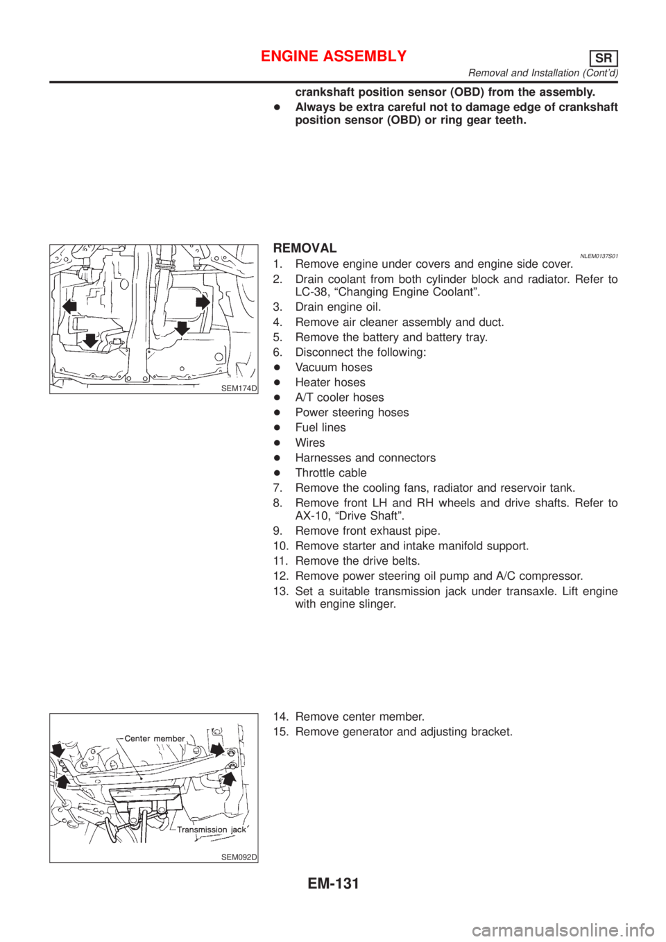
crankshaft position sensor (OBD) from the assembly.
+Always be extra careful not to damage edge of crankshaft
position sensor (OBD) or ring gear teeth.
SEM174D
REMOVALNLEM0137S011. Remove engine under covers and engine side cover.
2. Drain coolant from both cylinder block and radiator. Refer to
LC-38, ªChanging Engine Coolantº.
3. Drain engine oil.
4. Remove air cleaner assembly and duct.
5. Remove the battery and battery tray.
6. Disconnect the following:
+Vacuum hoses
+Heater hoses
+A/T cooler hoses
+Power steering hoses
+Fuel lines
+Wires
+Harnesses and connectors
+Throttle cable
7. Remove the cooling fans, radiator and reservoir tank.
8. Remove front LH and RH wheels and drive shafts. Refer to
AX-10, ªDrive Shaftº.
9. Remove front exhaust pipe.
10. Remove starter and intake manifold support.
11. Remove the drive belts.
12. Remove power steering oil pump and A/C compressor.
13. Set a suitable transmission jack under transaxle. Lift engine
with engine slinger.
SEM092D
14. Remove center member.
15. Remove generator and adjusting bracket.
ENGINE ASSEMBLYSR
Removal and Installation (Cont'd)
EM-131
Page 2389 of 3051
SEM040G
16. Remove engine mounting bolts from both sides, then slowly
lower transmission jack.
SEM195F
17. Remove engine with transaxle as shown.
INSTALLATIONNLEM0137S021. Install in the reverse order of removal.
ENGINE ASSEMBLYSR
Removal and Installation (Cont'd)
EM-132
Page 2428 of 3051
JEM114G
3. Remove air compressor bracket.
4. Remove lower oil pan bolts.
+Loosen bolts in the reverse order of that shown in the figure.
SEM544G
5. Remove lower oil pan.
a. Insert Tool between upper oil pan and lower oil pan.
+Be careful not to damage aluminum mating surface.
+Do not insert screwdriver, or oil pan flange will be
deformed.
SEM545G
b. Slide Tool by tapping on the side of the Tool with a hammer.
c. Remove lower oil pan.
6. Remove oil strainer.
7. Remove front exhaust tube and its support.
Refer to FE-23, ªRemoval and Installationº.
JEM553G
8. Set a suitable transmission jack under transaxle and hoist
engine with engine slinger.
+Place the jack as close to the center as possible for support.
9. Remove front and rear engine mounting nuts and bolts.
10. Remove center member.
11. Remove crankshaft position sensor (TDC sensor) from oil pan.
12. Remove oil pan cover.
OIL PANYD
Removal (Cont'd)
EM-171