2001 NISSAN ALMERA TINO transmission
[x] Cancel search: transmissionPage 980 of 3051
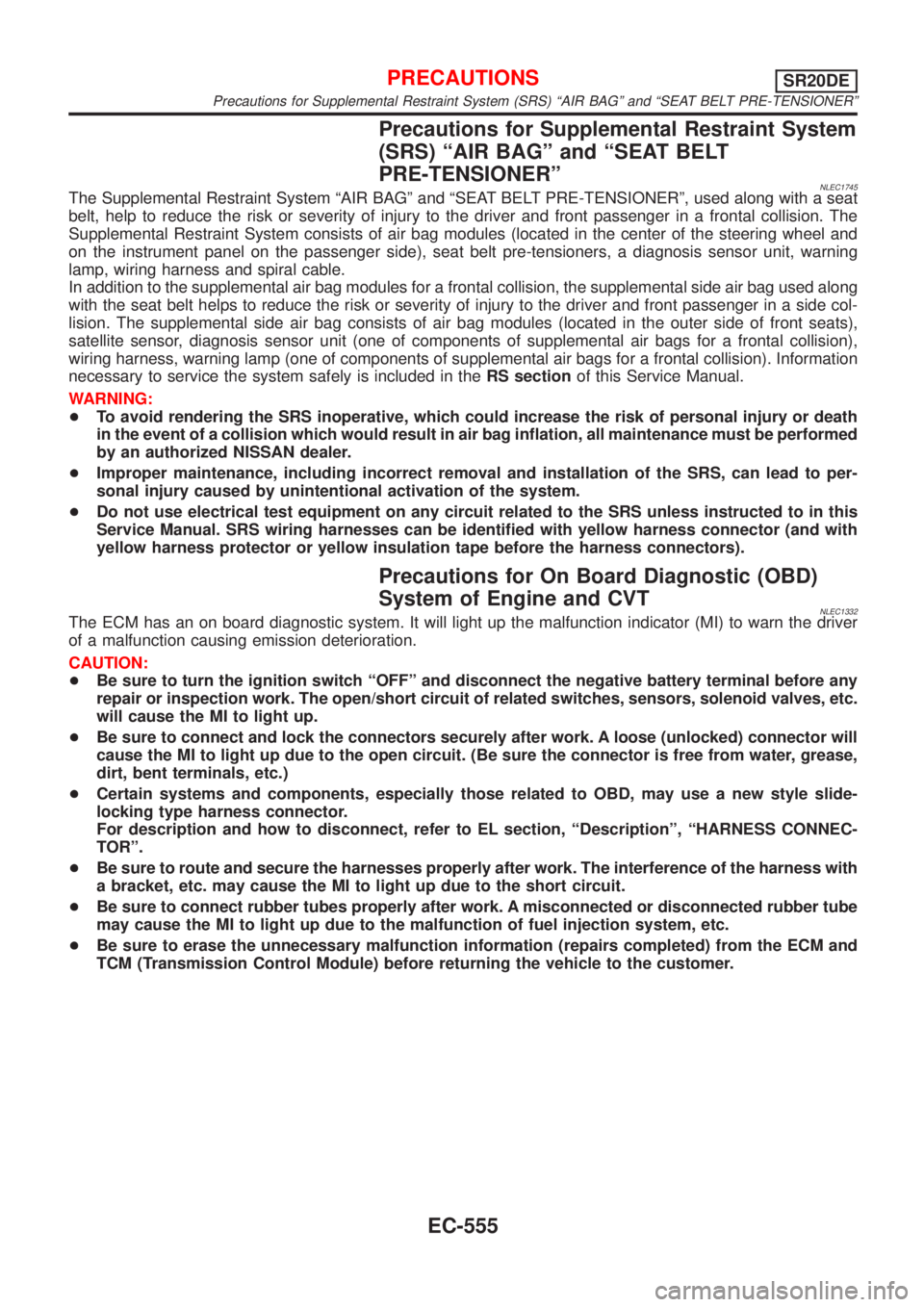
Precautions for Supplemental Restraint System
(SRS) ªAIR BAGº and ªSEAT BELT
PRE-TENSIONERº
NLEC1745The Supplemental Restraint System ªAIR BAGº and ªSEAT BELT PRE-TENSIONERº, used along with a seat
belt, help to reduce the risk or severity of injury to the driver and front passenger in a frontal collision. The
Supplemental Restraint System consists of air bag modules (located in the center of the steering wheel and
on the instrument panel on the passenger side), seat belt pre-tensioners, a diagnosis sensor unit, warning
lamp, wiring harness and spiral cable.
In addition to the supplemental air bag modules for a frontal collision, the supplemental side air bag used along
with the seat belt helps to reduce the risk or severity of injury to the driver and front passenger in a side col-
lision. The supplemental side air bag consists of air bag modules (located in the outer side of front seats),
satellite sensor, diagnosis sensor unit (one of components of supplemental air bags for a frontal collision),
wiring harness, warning lamp (one of components of supplemental air bags for a frontal collision). Information
necessary to service the system safely is included in theRS sectionof this Service Manual.
WARNING:
+To avoid rendering the SRS inoperative, which could increase the risk of personal injury or death
in the event of a collision which would result in air bag inflation, all maintenance must be performed
by an authorized NISSAN dealer.
+Improper maintenance, including incorrect removal and installation of the SRS, can lead to per-
sonal injury caused by unintentional activation of the system.
+Do not use electrical test equipment on any circuit related to the SRS unless instructed to in this
Service Manual. SRS wiring harnesses can be identified with yellow harness connector (and with
yellow harness protector or yellow insulation tape before the harness connectors).
Precautions for On Board Diagnostic (OBD)
System of Engine and CVT
NLEC1332The ECM has an on board diagnostic system. It will light up the malfunction indicator (MI) to warn the driver
of a malfunction causing emission deterioration.
CAUTION:
+Be sure to turn the ignition switch ªOFFº and disconnect the negative battery terminal before any
repair or inspection work. The open/short circuit of related switches, sensors, solenoid valves, etc.
will cause the MI to light up.
+Be sure to connect and lock the connectors securely after work. A loose (unlocked) connector will
cause the MI to light up due to the open circuit. (Be sure the connector is free from water, grease,
dirt, bent terminals, etc.)
+Certain systems and components, especially those related to OBD, may use a new style slide-
locking type harness connector.
For description and how to disconnect, refer to EL section, ªDescriptionº, ªHARNESS CONNEC-
TORº.
+Be sure to route and secure the harnesses properly after work. The interference of the harness with
a bracket, etc. may cause the MI to light up due to the short circuit.
+Be sure to connect rubber tubes properly after work. A misconnected or disconnected rubber tube
may cause the MI to light up due to the malfunction of fuel injection system, etc.
+Be sure to erase the unnecessary malfunction information (repairs completed) from the ECM and
TCM (Transmission Control Module) before returning the vehicle to the customer.
PRECAUTIONSSR20DE
Precautions for Supplemental Restraint System (SRS) ªAIR BAGº and ªSEAT BELT PRE-TENSIONERº
EC-555
Page 993 of 3051
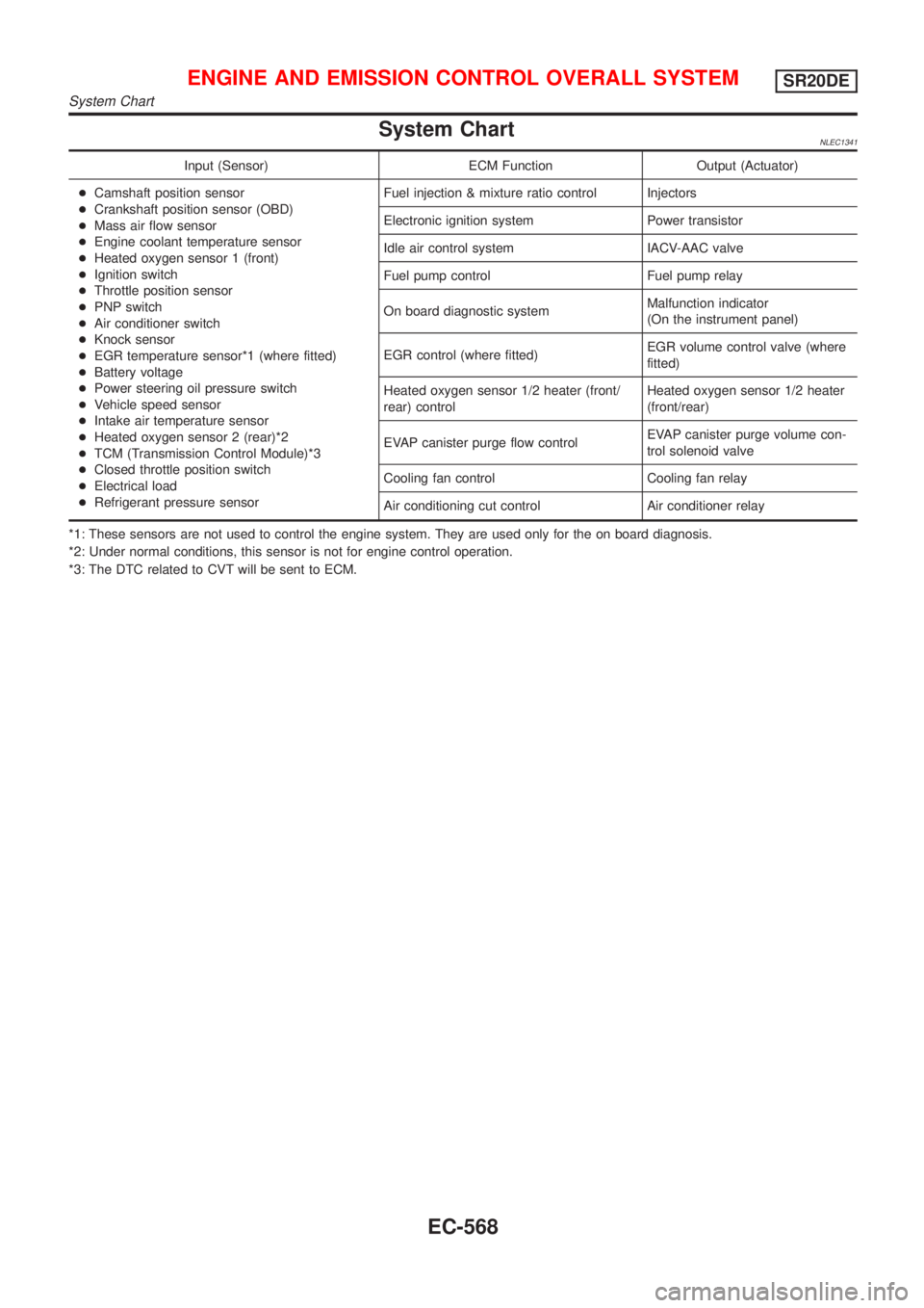
System ChartNLEC1341
Input (Sensor) ECM Function Output (Actuator)
+Camshaft position sensor
+Crankshaft position sensor (OBD)
+Mass air flow sensor
+Engine coolant temperature sensor
+Heated oxygen sensor 1 (front)
+Ignition switch
+Throttle position sensor
+PNP switch
+Air conditioner switch
+Knock sensor
+EGR temperature sensor*1 (where fitted)
+Battery voltage
+Power steering oil pressure switch
+Vehicle speed sensor
+Intake air temperature sensor
+Heated oxygen sensor 2 (rear)*2
+TCM (Transmission Control Module)*3
+Closed throttle position switch
+Electrical load
+Refrigerant pressure sensorFuel injection & mixture ratio control Injectors
Electronic ignition system Power transistor
Idle air control system IACV-AAC valve
Fuel pump control Fuel pump relay
On board diagnostic systemMalfunction indicator
(On the instrument panel)
EGR control (where fitted)EGR volume control valve (where
fitted)
Heated oxygen sensor 1/2 heater (front/
rear) controlHeated oxygen sensor 1/2 heater
(front/rear)
EVAP canister purge flow controlEVAP canister purge volume con-
trol solenoid valve
Cooling fan control Cooling fan relay
Air conditioning cut control Air conditioner relay
*1: These sensors are not used to control the engine system. They are used only for the on board diagnosis.
*2: Under normal conditions, this sensor is not for engine control operation.
*3: The DTC related to CVT will be sent to ECM.
ENGINE AND EMISSION CONTROL OVERALL SYSTEMSR20DE
System Chart
EC-568
Page 1006 of 3051
SEF217Z
SEF454Y
SEF455Y
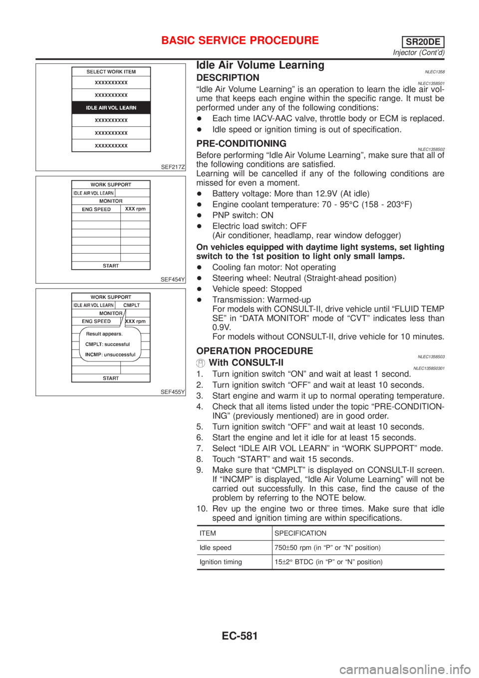
Idle Air Volume LearningNLEC1358DESCRIPTIONNLEC1358S01ªIdle Air Volume Learningº is an operation to learn the idle air vol-
ume that keeps each engine within the specific range. It must be
performed under any of the following conditions:
+Each time IACV-AAC valve, throttle body or ECM is replaced.
+Idle speed or ignition timing is out of specification.
PRE-CONDITIONINGNLEC1358S02Before performing ªIdle Air Volume Learningº, make sure that all of
the following conditions are satisfied.
Learning will be cancelled if any of the following conditions are
missed for even a moment.
+Battery voltage: More than 12.9V (At idle)
+Engine coolant temperature: 70 - 95ÉC (158 - 203ÉF)
+PNP switch: ON
+Electric load switch: OFF
(Air conditioner, headlamp, rear window defogger)
On vehicles equipped with daytime light systems, set lighting
switch to the 1st position to light only small lamps.
+Cooling fan motor: Not operating
+Steering wheel: Neutral (Straight-ahead position)
+Vehicle speed: Stopped
+Transmission: Warmed-up
For models with CONSULT-II, drive vehicle until ªFLUID TEMP
SEº in ªDATA MONITORº mode of ªCVTº indicates less than
0.9V.
For models without CONSULT-II, drive vehicle for 10 minutes.
OPERATION PROCEDURENLEC1358S03With CONSULT-IINLEC1358S03011. Turn ignition switch ªONº and wait at least 1 second.
2. Turn ignition switch ªOFFº and wait at least 10 seconds.
3. Start engine and warm it up to normal operating temperature.
4. Check that all items listed under the topic ªPRE-CONDITION-
INGº (previously mentioned) are in good order.
5. Turn ignition switch ªOFFº and wait at least 10 seconds.
6. Start the engine and let it idle for at least 15 seconds.
7. Select ªIDLE AIR VOL LEARNº in ªWORK SUPPORTº mode.
8. Touch ªSTARTº and wait 15 seconds.
9. Make sure that ªCMPLTº is displayed on CONSULT-II screen.
If ªINCMPº is displayed, ªIdle Air Volume Learningº will not be
carried out successfully. In this case, find the cause of the
problem by referring to the NOTE below.
10. Rev up the engine two or three times. Make sure that idle
speed and ignition timing are within specifications.
ITEM SPECIFICATION
Idle speed 750±50 rpm (in ªPº or ªNº position)
Ignition timing 15±2É BTDC (in ªPº or ªNº position)
BASIC SERVICE PROCEDURESR20DE
Injector (Cont'd)
EC-581
Page 1016 of 3051
+The time required for each diagnosis varies with road surface conditions, weather, altitude, individual driv-
ing habits, etc.
Zone A refers to the range where the time required, for the diagnosis under normal conditions*, is the
shortest. Zone B refers to the range where the diagnosis can still be performed if the diagnosis is not
completed within zone A.
*: Normal conditions refer to the following:
þ Sea level
þ Flat road
þ Ambient air temperature: 20 - 30ÉC (68 - 86ÉF)
þ Diagnosis is performed as quickly as possible under normal conditions.
Under different conditions [For example: ambient air temperature other than 20 - 30ÉC (68 - 86ÉF)], diag-
nosis may also be performed.
Pattern 1:
+The engine is started at the engine coolant temperature of þ10 to 35ÉC (14 to 95ÉF) (where the volt-
age between the ECM terminal 70 and ground is 3.0 - 4.3V).
+The engine must be operated at idle speed until the engine coolant temperature is greater than 70ÉC
(158ÉF) (where the voltage between the ECM terminal 70 and ground is lower than 1.4V).
Pattern 2:
+When steady-state driving is performed again even after it is interrupted, each diagnosis can be conducted.
In this case, the time required for diagnosis may be extended.
*1: Depress the accelerator pedal until vehicle speed is 90 km/h (56 MPH), then release the accelerator pedal
and keep it released for more than 10 seconds. Depress the accelerator pedal until vehicle speed is 90 km/h
(56 MPH) again.
*2: Checking the vehicle speed with GST is advised.
Suggested transmission gear position for CVT models
Set the selector lever in the ªDº position with ªSPORTS MODE SWº ON.
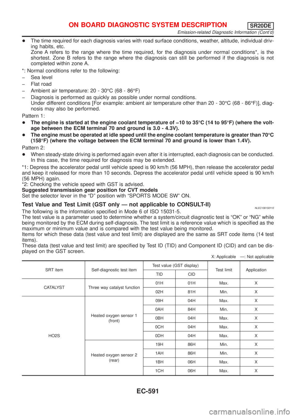
Test Value and Test Limit (GST only Ð not applicable to CONSULT-II)NLEC1361S0110The following is the information specified in Mode 6 of ISO 15031-5.
The test value is a parameter used to determine whether a system/circuit diagnostic test is ªOKº or ªNGº while
being monitored by the ECM during self-diagnosis. The test limit is a reference value which is specified as the
maximum or minimum value and is compared with the test value being monitored.
Items for which these data (test value and test limit) are displayed are the same as SRT code items (14 test
items).
These data (test value and test limit) are specified by Test ID (TID) and Component ID (CID) and can be dis-
played on the GST screen.
X: Applicable Ð: Not applicable
SRT item Self-diagnostic test itemTest value (GST display)
Test limit Application
TID CID
CATALYST Three way catalyst function01H 01H Max. X
02H 81H Min. X
HO2SHeated oxygen sensor 1
(front)09H 04H Max. X
0AH 84H Min. X
0BH 04H Max. X
0CH 04H Max. X
0DH 04H Max. X
Heated oxygen sensor 2
(rear)19H 86H Min. X
1AH 86H Min. X
1BH 06H Max. X
1CH 06H Max. X
ON BOARD DIAGNOSTIC SYSTEM DESCRIPTIONSR20DE
Emission-related Diagnostic Information (Cont'd)
EC-591
Page 1019 of 3051
Items
(CONSULT-II screen terms)DTC*1 SRT codeTest value/Test
limit
(GST only)1st trip DTC*1 Reference page
LINE PRESS SEN P1791 Ð Ð XRefer to AT sec-
tion.
*1: 1st trip DTC No. is the same as DTC No.
*2: These are not displayed with GST.
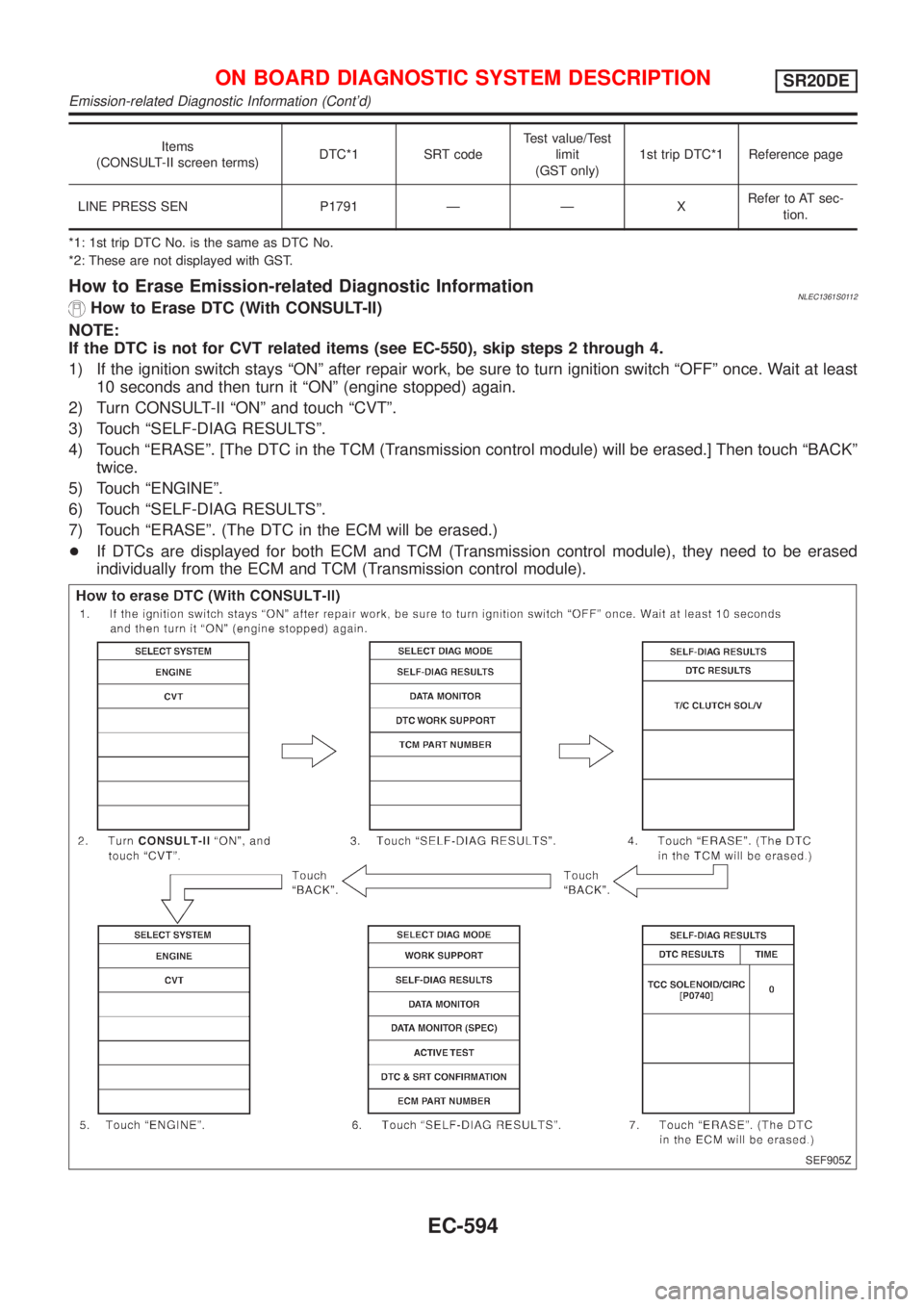
How to Erase Emission-related Diagnostic InformationNLEC1361S0112How to Erase DTC (With CONSULT-II)
NOTE:
If the DTC is not for CVT related items (see EC-550), skip steps 2 through 4.
1) If the ignition switch stays ªONº after repair work, be sure to turn ignition switch ªOFFº once. Wait at least
10 seconds and then turn it ªONº (engine stopped) again.
2) Turn CONSULT-II ªONº and touch ªCVTº.
3) Touch ªSELF-DIAG RESULTSº.
4) Touch ªERASEº. [The DTC in the TCM (Transmission control module) will be erased.] Then touch ªBACKº
twice.
5) Touch ªENGINEº.
6) Touch ªSELF-DIAG RESULTSº.
7) Touch ªERASEº. (The DTC in the ECM will be erased.)
+If DTCs are displayed for both ECM and TCM (Transmission control module), they need to be erased
individually from the ECM and TCM (Transmission control module).
SEF905Z
ON BOARD DIAGNOSTIC SYSTEM DESCRIPTIONSR20DE
Emission-related Diagnostic Information (Cont'd)
EC-594
Page 1047 of 3051
DESCRIPTION FOR WORK FLOWNLEC1368S01
STEP DESCRIPTION
STEP IGet detailed information about the conditions and the environment when the incident/symptom occurred using
the ªDIAGNOSTIC WORK SHEETº, EC-620.
STEP IIBefore confirming the concern, check and write down (print out using CONSULT-II or GST) the (1st trip) DTC
and the (1st trip) freeze frame data, then erase the DTC and the data. (Refer to EC-594, EC-596.) The (1st trip)
DTC and the (1st trip) freeze frame data can be used when duplicating the incident at STEP III & IV.
If the incident cannot be verified, perform ªTROUBLE DIAGNOSIS FOR INTERMITTENT INCIDENTº, EC-670.
Study the relationship between the cause, specified by (1st trip) DTC, and the symptom described by the cus-
tomer. (The ªSymptom Matrix Chartº will be useful. See EC-648.)
Also check related service bulletins for information.
STEP IIITry to confirm the symptom and under what conditions the incident occurs.
The ªDIAGNOSTIC WORK SHEETº and the freeze frame data are useful to verify the incident. Connect CON-
SULT-II to the vehicle in DATA MONITOR (AUTO TRIG) mode and check real time diagnosis results.
If the incident cannot be verified, perform ªTROUBLE DIAGNOSIS FOR INTERMITTENT INCIDENTº, EC-670.
If the malfunction code is detected, skip STEP IV and perform STEP V.
STEP IVTry to detect the (1st trip) DTC by driving in (or performing) the ªDTC Confirmation Procedureº. Check and read
the (1st trip) DTC and (1st trip) freeze frame data by using CONSULT-II or GST.
During the (1st trip) DTC verification, be sure to connect CONSULT-II to the vehicle in DATA MONITOR (AUTO
TRIG) mode and check real time diagnosis results.
If the incident cannot be verified, perform ªTROUBLE DIAGNOSIS FOR INTERMITTENT INCIDENTº, EC-670.
In case the ªDTC Confirmation Procedureº is not available, perform the ªOverall Function Checkº instead. The
(1st trip) DTC cannot be displayed by this check, however, this simplified ªcheckº is an effective alternative.
The ªNGº result of the ªOverall Function Checkº is the same as the (1st trip) DTC detection.
STEP VTake the appropriate action based on the results of STEP I through IV.
If the malfunction code is indicated, proceed to TROUBLE DIAGNOSIS FOR DTC PXXXX.
If the normal code is indicated, proceed refer to ªBASIC INSPECTIONº, EC-623. If CONSULT-II is available, per-
form ªDATA MONITOR (SPEC)º mode with CONSULT-II and proceed to the ªTROUBLE DIAGNOSIS-SPECIFI-
CATION VALUEº, EC-666. (If malfunction is detected, proceed to ªREPAIR/REPLACEº. Then perform inspections
according to the Symptom Matrix Chart. (Refer to EC-648.)
STEP VIIdentify where to begin diagnosis based on the relationship study between symptom and possible causes.
Inspect the system for mechanical binding, loose connectors or wiring damage using (tracing) ªHarness Layoutsº.
Gently shake the related connectors, components or wiring harness with CONSULT-II set in ªDATA MONITOR
(AUTO TRIG)º mode.
Check the voltage of the related ECM terminals or monitor the output data from the related sensors with CON-
SULT-II. Refer to EC-657.
The ªDiagnostic Procedureº in EC section contains a description based on open circuit inspection. A short circuit
inspection is also required for the circuit check in the Diagnostic Procedure. For details, refer to GI section
(ªHOW TO PERFORM EFFICIENT DIAGNOSIS FOR AN ELECTRICAL INCIDENTº, ªCircuit Inspectionº).
Repair or replace the malfunction parts.
If malfunctioning part cannot be detected, perform ªTROUBLE DIAGNOSIS FOR INTERMITTENT INCIDENTº,
EC-670.
STEP VIIOnce you have repaired the circuit or replaced a component, you need to run the engine in the same conditions
and circumstances which resulted in the customer's initial complaint.
Perform the ªDTC Confirmation Procedureº and confirm the normal code [DTC No. P0000] is detected. If the
incident is still detected in the final check, perform STEP VI by using a different method from the previous one.
Before returning the vehicle to the customer, be sure to erase the unnecessary (already fixed) (1st trip) DTC in
ECM and TCM (Transmission control module). (Refer to EC-594, EC-596.)
TROUBLE DIAGNOSIS Ð INTRODUCTIONSR20DE
Work Flow (Cont'd)
EC-622
Page 1062 of 3051
29 CHECK TARGET IDLE SPEED
Without CONSULT-II
1. Start engine and warm it up to normal operating temperature.
2. Check idle speed.
750±50 rpm (in ªPº or ªNº position)
OK or NG
OK©GO TO 32.
NG©GO TO 30.
30 PERFORM IDLE AIR VOLUME LEARNING
Refer to ªIdle Air Volume Learningº, EC-581.
Is the result CMPLT or INCMP?
CMPLT or INCMP
CMPLT©GO TO 31.
INCMP©Follow the instruction of ªIdle Air Volume Learningº.
31 CHECK TARGET IDLE SPEED AGAIN
1. Start engine and warm it up to normal operating temperature.
2. Check idle speed.
750±50 rpm (in ªPº or ªNº position)
OK or NG
OK©GO TO 32.
NG©GO TO 21.
32 ERASE UNNECESSARY DTC
After this inspection, unnecessary DTC No. might be displayed.
Erase the stored memory in ECM and TCM (Transmission control module).
Refer to ªHOW TO ERASE EMISSION-RELATED DIAGNOSTIC INFORMATIONº, EC-594, 596 and ªHOW TO ERASE
DTCº, AT-19 .
©INSPECTION END
TROUBLE DIAGNOSIS Ð BASIC INSPECTIONSR20DE
Basic Inspection (Models with Throttle Opener) (Cont'd)
EC-637
Page 1091 of 3051
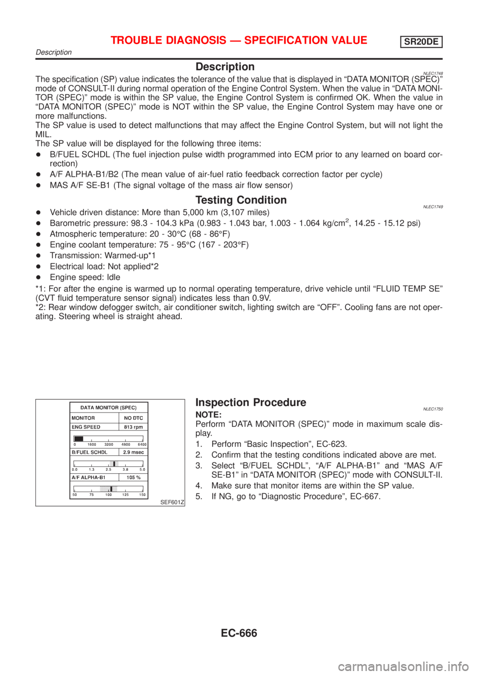
DescriptionNLEC1748The specification (SP) value indicates the tolerance of the value that is displayed in ªDATA MONITOR (SPEC)º
mode of CONSULT-II during normal operation of the Engine Control System. When the value in ªDATA MONI-
TOR (SPEC)º mode is within the SP value, the Engine Control System is confirmed OK. When the value in
ªDATA MONITOR (SPEC)º mode is NOT within the SP value, the Engine Control System may have one or
more malfunctions.
The SP value is used to detect malfunctions that may affect the Engine Control System, but will not light the
MIL.
The SP value will be displayed for the following three items:
+B/FUEL SCHDL (The fuel injection pulse width programmed into ECM prior to any learned on board cor-
rection)
+A/F ALPHA-B1/B2 (The mean value of air-fuel ratio feedback correction factor per cycle)
+MAS A/F SE-B1 (The signal voltage of the mass air flow sensor)
Testing ConditionNLEC1749+Vehicle driven distance: More than 5,000 km (3,107 miles)
+Barometric pressure: 98.3 - 104.3 kPa (0.983 - 1.043 bar, 1.003 - 1.064 kg/cm2, 14.25 - 15.12 psi)
+Atmospheric temperature: 20 - 30ÉC (68 - 86ÉF)
+Engine coolant temperature: 75 - 95ÉC (167 - 203ÉF)
+Transmission: Warmed-up*1
+Electrical load: Not applied*2
+Engine speed: Idle
*1: For after the engine is warmed up to normal operating temperature, drive vehicle until ªFLUID TEMP SEº
(CVT fluid temperature sensor signal) indicates less than 0.9V.
*2: Rear window defogger switch, air conditioner switch, lighting switch are ªOFFº. Cooling fans are not oper-
ating. Steering wheel is straight ahead.
SEF601Z
Inspection ProcedureNLEC1750NOTE:
Perform ªDATA MONITOR (SPEC)º mode in maximum scale dis-
play.
1. Perform ªBasic Inspectionº, EC-623.
2. Confirm that the testing conditions indicated above are met.
3. Select ªB/FUEL SCHDLº, ªA/F ALPHA-B1º and ªMAS A/F
SE-B1º in ªDATA MONITOR (SPEC)º mode with CONSULT-II.
4. Make sure that monitor items are within the SP value.
5. If NG, go to ªDiagnostic Procedureº, EC-667.
TROUBLE DIAGNOSIS Ð SPECIFICATION VALUESR20DE
Description
EC-666