Page 1118 of 3051
4 DETECT MALFUNCTIONING PART
Check the following.
+Joint connector-1 (where fitted)
+Harness connectors E75, F35 (where fitted)
+Harness for open or short between ECM and intake air temperature sensor
+Harness for open or short between TCM (Transmission Control Module) and intake air temperature sensor (where fit-
ted)
©Repair open circuit or short to power in harness or connectors.
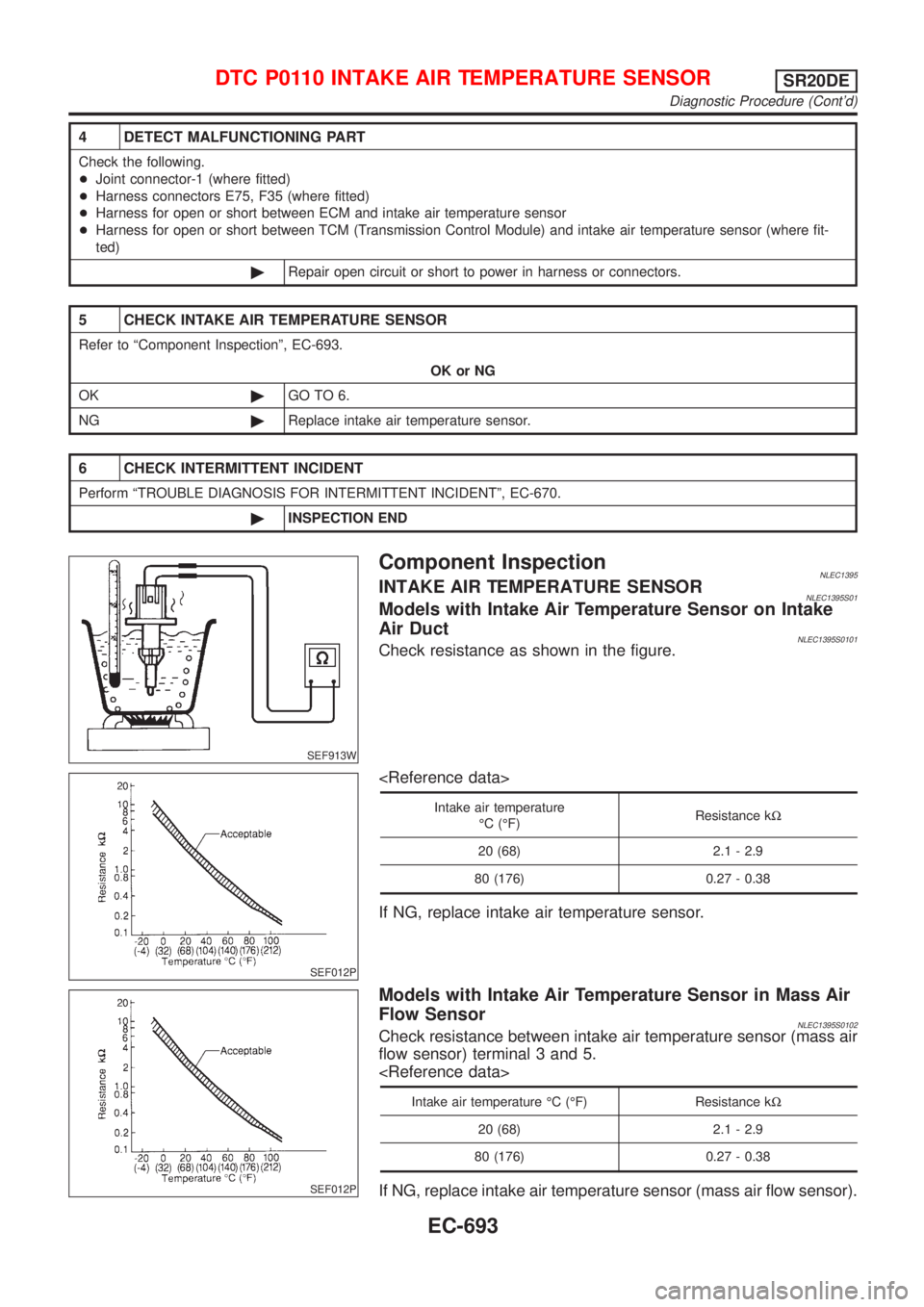
5 CHECK INTAKE AIR TEMPERATURE SENSOR
Refer to ªComponent Inspectionº, EC-693.
OK or NG
OK©GO TO 6.
NG©Replace intake air temperature sensor.
6 CHECK INTERMITTENT INCIDENT
Perform ªTROUBLE DIAGNOSIS FOR INTERMITTENT INCIDENTº, EC-670.
©INSPECTION END
SEF913W
Component InspectionNLEC1395INTAKE AIR TEMPERATURE SENSORNLEC1395S01Models with Intake Air Temperature Sensor on Intake
Air Duct
NLEC1395S0101Check resistance as shown in the figure.
SEF012P
Intake air temperature
ÉC (ÉF)Resistance kW
20 (68) 2.1 - 2.9
80 (176) 0.27 - 0.38
If NG, replace intake air temperature sensor.
SEF012P
Models with Intake Air Temperature Sensor in Mass Air
Flow Sensor
NLEC1395S0102Check resistance between intake air temperature sensor (mass air
flow sensor) terminal 3 and 5.
Intake air temperature ÉC (ÉF) Resistance kW
20 (68) 2.1 - 2.9
80 (176) 0.27 - 0.38
If NG, replace intake air temperature sensor (mass air flow sensor).
DTC P0110 INTAKE AIR TEMPERATURE SENSORSR20DE
Diagnostic Procedure (Cont'd)
EC-693
Page 1124 of 3051
4 DETECT MALFUNCTIONING PART
Check the following.
+Joint connector-1 (where fitted)
+Joint connector F46 (where fitted)
+Harness for open or short between ECM and engine coolant temperature sensor
+Harness for open or short between engine coolant temperature sensor and TCM (Transmission Control Module)
©Repair open circuit or short to power in harness or connectors.
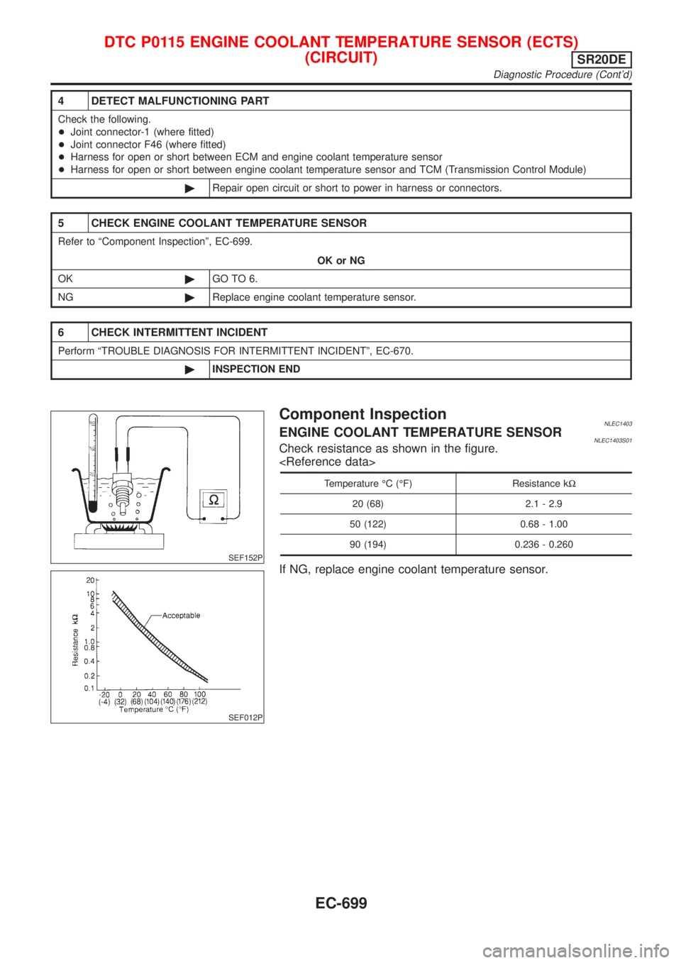
5 CHECK ENGINE COOLANT TEMPERATURE SENSOR
Refer to ªComponent Inspectionº, EC-699.
OK or NG
OK©GO TO 6.
NG©Replace engine coolant temperature sensor.
6 CHECK INTERMITTENT INCIDENT
Perform ªTROUBLE DIAGNOSIS FOR INTERMITTENT INCIDENTº, EC-670.
©INSPECTION END
SEF152P
SEF012P
Component InspectionNLEC1403ENGINE COOLANT TEMPERATURE SENSORNLEC1403S01Check resistance as shown in the figure.
Temperature ÉC (ÉF) Resistance kW
20 (68) 2.1 - 2.9
50 (122) 0.68 - 1.00
90 (194) 0.236 - 0.260
If NG, replace engine coolant temperature sensor.
DTC P0115 ENGINE COOLANT TEMPERATURE SENSOR (ECTS)
(CIRCUIT)
SR20DE
Diagnostic Procedure (Cont'd)
EC-699
Page 1131 of 3051
4 CHECK GROUND CIRCUIT
1. Turn ignition switch ªOFFº.
2. Check harness continuity between throttle position sensor terminal 1 and engine ground.
Refer to wiring diagram.
Continuity should exist.
3. Also check harness for short to power.
OK or NG
OK©GO TO 6.
NG©GO TO 5.
5 DETECT MALFUNCTIONING PART
Check the following.
+Joint connector-1 (where fitted)
+Joint connector F46 (where fitted)
+Harness for open or short between ECM terminal 58 and throttle position sensor
+Harness for open or short between ECM terminal 58 and TCM (Transmission Control Module)
©Repair open circuit or short to power in harness or connectors.
6 CHECK INPUT SIGNAL CIRCUIT
1. Disconnect ECM harness connector.
2. Check harness continuity between ECM terminal 92 and throttle position sensor terminal 2.
Refer to wiring diagram.
Continuity should exist.
3. Also check harness for short to ground and short to power.
OK or NG
OK©GO TO 7.
NG©Repair open circuit or short to ground or short to power in harness or connectors.
7 CHECK THROTTLE POSITION SENSOR
Refer to ªComponent Inspectionº, EC-707.
OK or NG
OK©GO TO 8.
NG©Replace throttle position sensor. To adjust it, perform ªBasic Inspectionº, EC-623.
8 CHECK INTERMITTENT INCIDENT
Perform ªTROUBLE DIAGNOSIS FOR INTERMITTENT INCIDENTº, EC-670.
©INSPECTION END
DTC P0120 THROTTLE POSITION SENSORSR20DE
Diagnostic Procedure (Cont'd)
EC-706
Page 1249 of 3051
4 CHECK GROUND CIRCUIT
1. Reconnect ECM harness connector.
2. Check harness continuity between CKPS (OBD) terminal 2 and engine ground.
Refer to woring diagram.
Continuity should exist.
3. Also check harness for short to power.
OK or NG
OK©GO TO 6.
NG©GO TO 5.
5 DETECT MALFUNCTIONING PART
Check the following.
+Joint connector-1 (where fitted)
+Joint connector F46 (where fitted)
+Harness for open or short between crankshaft position sensor (OBD) and ECM
+Harness for open or short between crankshaft position sensor (OBD) and TCM (Transmission control module)
©Repair open circuit or short to power in harness or connectors.
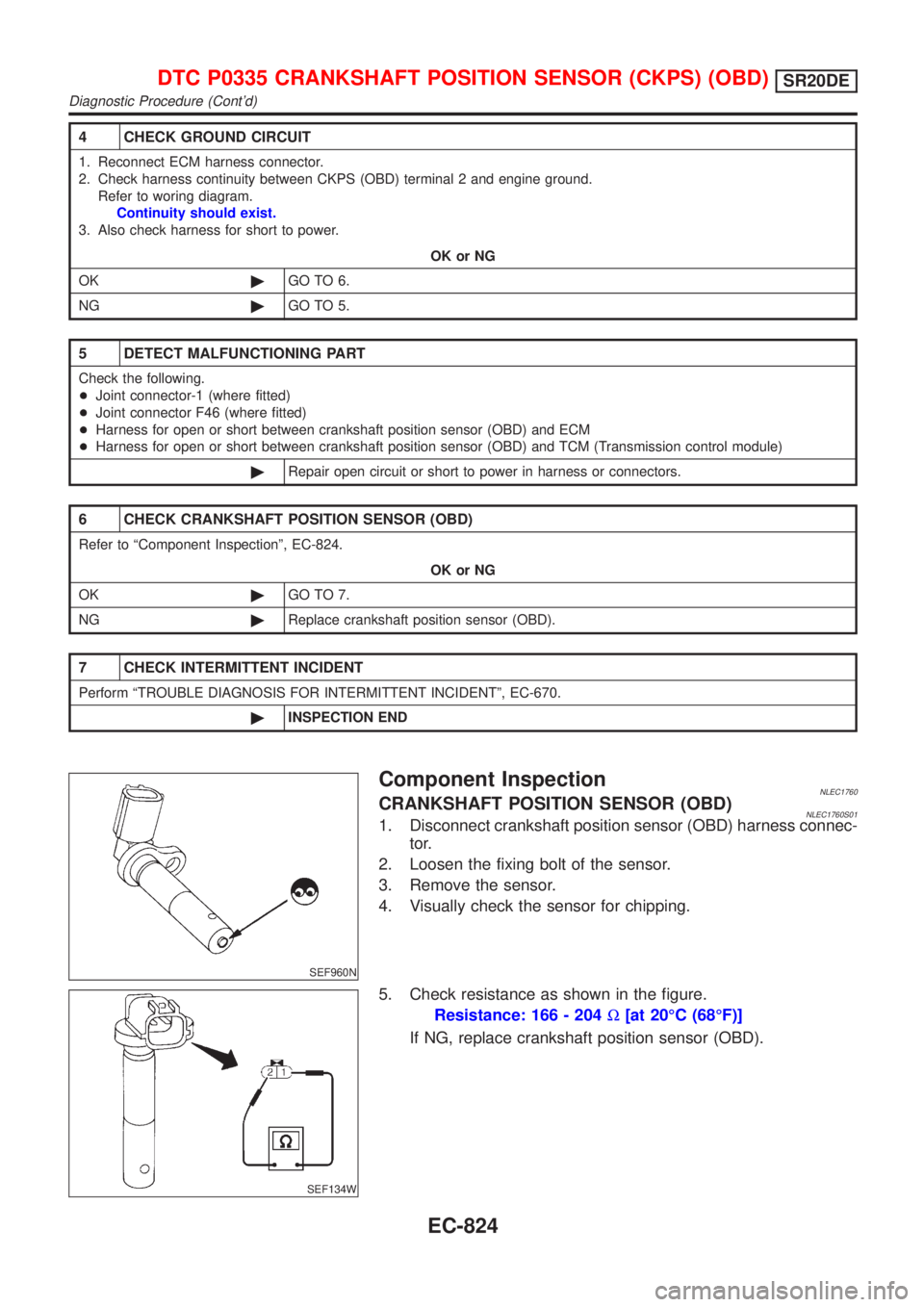
6 CHECK CRANKSHAFT POSITION SENSOR (OBD)
Refer to ªComponent Inspectionº, EC-824.
OK or NG
OK©GO TO 7.
NG©Replace crankshaft position sensor (OBD).
7 CHECK INTERMITTENT INCIDENT
Perform ªTROUBLE DIAGNOSIS FOR INTERMITTENT INCIDENTº, EC-670.
©INSPECTION END
SEF960N
Component InspectionNLEC1760CRANKSHAFT POSITION SENSOR (OBD)NLEC1760S011. Disconnect crankshaft position sensor (OBD) harness connec-
tor.
2. Loosen the fixing bolt of the sensor.
3. Remove the sensor.
4. Visually check the sensor for chipping.
SEF134W
5. Check resistance as shown in the figure.
Resistance: 166 - 204W[at 20ÉC (68ÉF)]
If NG, replace crankshaft position sensor (OBD).
DTC P0335 CRANKSHAFT POSITION SENSOR (CKPS) (OBD)SR20DE
Diagnostic Procedure (Cont'd)
EC-824
Page 1259 of 3051
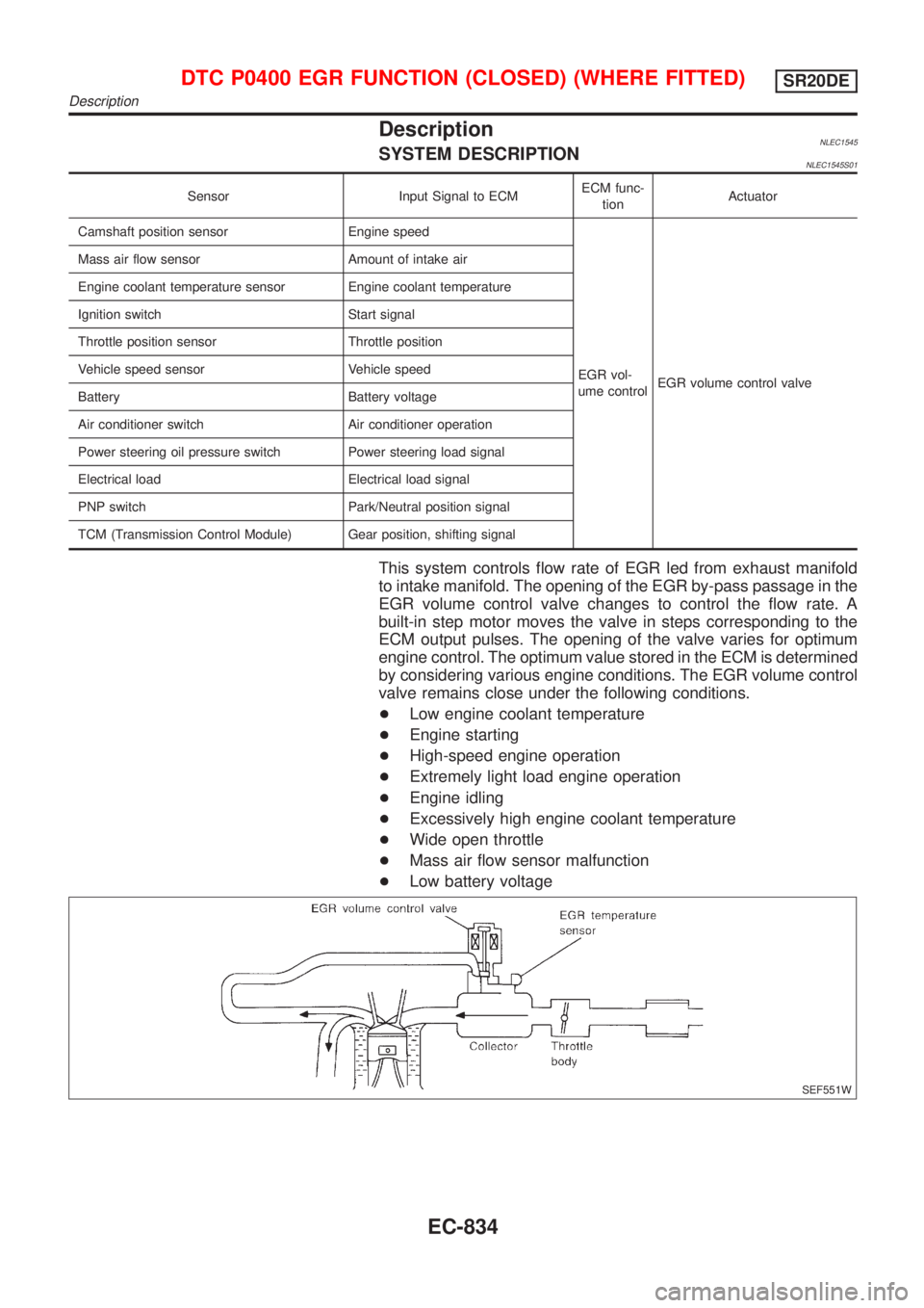
DescriptionNLEC1545SYSTEM DESCRIPTIONNLEC1545S01
Sensor Input Signal to ECMECM func-
tionActuator
Camshaft position sensor Engine speed
EGR vol-
ume controlEGR volume control valve Mass air flow sensor Amount of intake air
Engine coolant temperature sensor Engine coolant temperature
Ignition switch Start signal
Throttle position sensor Throttle position
Vehicle speed sensor Vehicle speed
Battery Battery voltage
Air conditioner switch Air conditioner operation
Power steering oil pressure switch Power steering load signal
Electrical load Electrical load signal
PNP switch Park/Neutral position signal
TCM (Transmission Control Module) Gear position, shifting signal
This system controls flow rate of EGR led from exhaust manifold
to intake manifold. The opening of the EGR by-pass passage in the
EGR volume control valve changes to control the flow rate. A
built-in step motor moves the valve in steps corresponding to the
ECM output pulses. The opening of the valve varies for optimum
engine control. The optimum value stored in the ECM is determined
by considering various engine conditions. The EGR volume control
valve remains close under the following conditions.
+Low engine coolant temperature
+Engine starting
+High-speed engine operation
+Extremely light load engine operation
+Engine idling
+Excessively high engine coolant temperature
+Wide open throttle
+Mass air flow sensor malfunction
+Low battery voltage
SEF551W
DTC P0400 EGR FUNCTION (CLOSED) (WHERE FITTED)SR20DE
Description
EC-834
Page 1266 of 3051
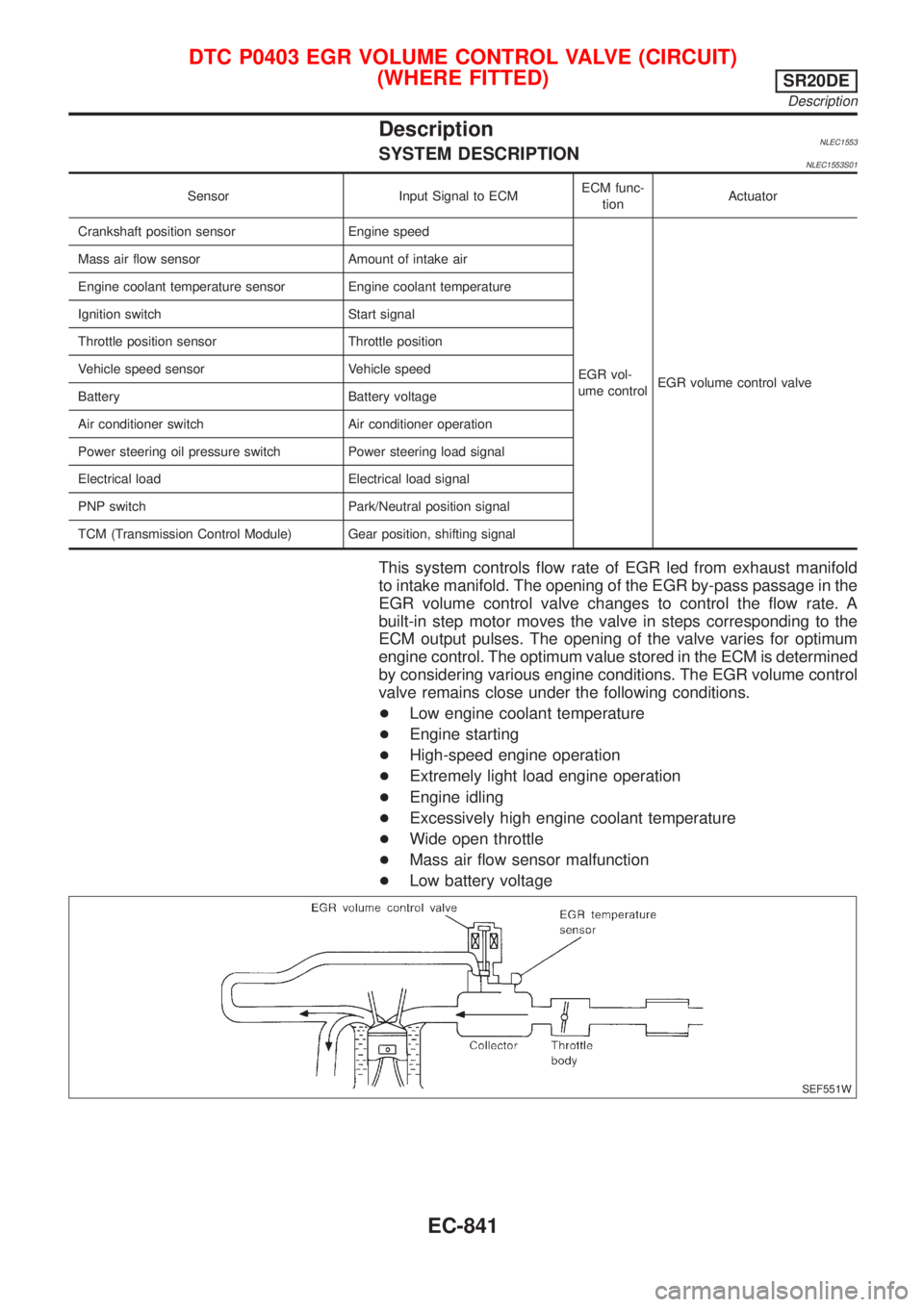
DescriptionNLEC1553SYSTEM DESCRIPTIONNLEC1553S01
Sensor Input Signal to ECMECM func-
tionActuator
Crankshaft position sensor Engine speed
EGR vol-
ume controlEGR volume control valve Mass air flow sensor Amount of intake air
Engine coolant temperature sensor Engine coolant temperature
Ignition switch Start signal
Throttle position sensor Throttle position
Vehicle speed sensor Vehicle speed
Battery Battery voltage
Air conditioner switch Air conditioner operation
Power steering oil pressure switch Power steering load signal
Electrical load Electrical load signal
PNP switch Park/Neutral position signal
TCM (Transmission Control Module) Gear position, shifting signal
This system controls flow rate of EGR led from exhaust manifold
to intake manifold. The opening of the EGR by-pass passage in the
EGR volume control valve changes to control the flow rate. A
built-in step motor moves the valve in steps corresponding to the
ECM output pulses. The opening of the valve varies for optimum
engine control. The optimum value stored in the ECM is determined
by considering various engine conditions. The EGR volume control
valve remains close under the following conditions.
+Low engine coolant temperature
+Engine starting
+High-speed engine operation
+Extremely light load engine operation
+Engine idling
+Excessively high engine coolant temperature
+Wide open throttle
+Mass air flow sensor malfunction
+Low battery voltage
SEF551W
DTC P0403 EGR VOLUME CONTROL VALVE (CIRCUIT)
(WHERE FITTED)
SR20DE
Description
EC-841
Page 1295 of 3051
9 REPLACE IACV-AAC VALVE
1. Replace IACV-AAC valve assembly.
2. Perform ªIdle Air Volume Learningº, EC-581.
Is the result CMPLT or INCMP?
CMPLT or INCMP
CMPLT©INSPECTION END
INCMP©Follow the construction of ªIdle Air Volume Learningº.
10 CHECK TARGET IDLE SPEED
1. Turn ignition switch ªOFFº.
2. Reconnect all harness connectors and vacuum hoses.
3. Start engine and warm it up to normal operating temperature.
4. Also warm up transmission to normal operating temperature.
+For models with CONSULT-II, drive vehicle until ªFLUID TEMP SEº in ªDATA MONITORº mode of ªCVTº system indi-
cates less than 0.9V.
+For models without CONSULT-II, drive vehicle for 10 minutes.
5. Stop vehicle with engine running.
6. Check target idle speed.
750±50 rpm
OK or NG
OK©GO TO 11.
NG©Perform ªIdle Air Volume Learningº, EC-581.
11 CHECK INTERMITTENT INCIDENT
Perform ªTROUBLE DIAGNOSIS FOR INTERMITTENT INCIDENTº, EC-670.
©INSPECTION END
DTC P0505 IDLE AIR CONTROL VALVE (IACV) Ð AUXILIARY AIR CONTROL
(AAC) VALVE
SR20DE
Diagnostic Procedure (Cont'd)
EC-870
Page 1338 of 3051
Diagnostic ProcedureNLEC1922
1 RETIGHTEN GROUND SCREWS
1. Turn ignition switch ªOFFº.
2. Loosen and retighten engine ground screws.
©GO TO 2.
2 CHECK INPUT SIGNAL CIRCUIT
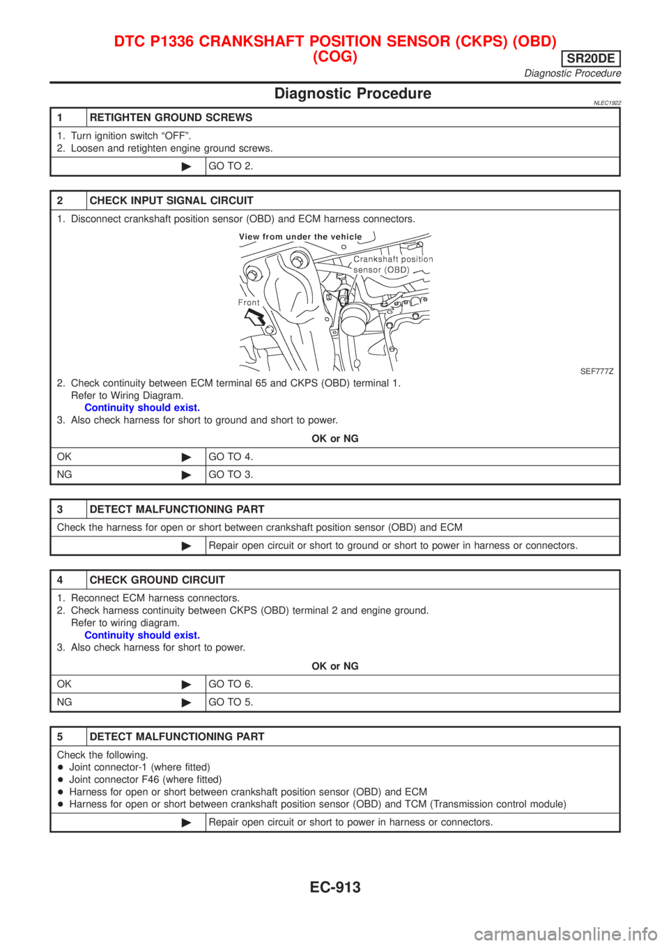
1. Disconnect crankshaft position sensor (OBD) and ECM harness connectors.
SEF777Z
2. Check continuity between ECM terminal 65 and CKPS (OBD) terminal 1.
Refer to Wiring Diagram.
Continuity should exist.
3. Also check harness for short to ground and short to power.
OK or NG
OK©GO TO 4.
NG©GO TO 3.
3 DETECT MALFUNCTIONING PART
Check the harness for open or short between crankshaft position sensor (OBD) and ECM
©Repair open circuit or short to ground or short to power in harness or connectors.
4 CHECK GROUND CIRCUIT
1. Reconnect ECM harness connectors.
2. Check harness continuity between CKPS (OBD) terminal 2 and engine ground.
Refer to wiring diagram.
Continuity should exist.
3. Also check harness for short to power.
OK or NG
OK©GO TO 6.
NG©GO TO 5.
5 DETECT MALFUNCTIONING PART
Check the following.
+Joint connector-1 (where fitted)
+Joint connector F46 (where fitted)
+Harness for open or short between crankshaft position sensor (OBD) and ECM
+Harness for open or short between crankshaft position sensor (OBD) and TCM (Transmission control module)
©Repair open circuit or short to power in harness or connectors.
DTC P1336 CRANKSHAFT POSITION SENSOR (CKPS) (OBD)
(COG)
SR20DE
Diagnostic Procedure
EC-913