2001 NISSAN ALMERA TINO display
[x] Cancel search: displayPage 543 of 3051
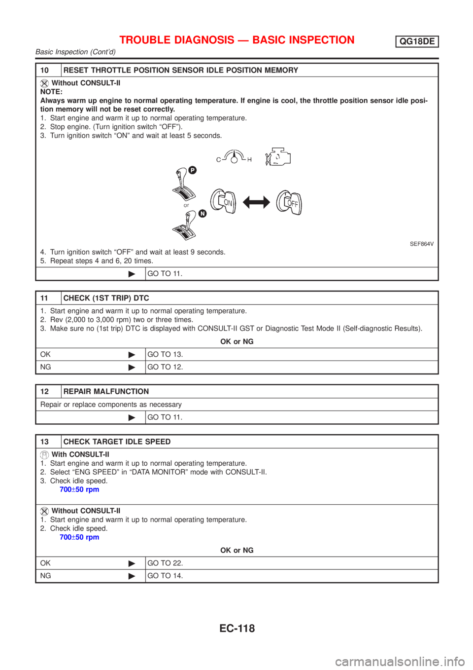
10 RESET THROTTLE POSITION SENSOR IDLE POSITION MEMORY
Without CONSULT-II
NOTE:
Always warm up engine to normal operating temperature. If engine is cool, the throttle position sensor idle posi-
tion memory will not be reset correctly.
1. Start engine and warm it up to normal operating temperature.
2. Stop engine. (Turn ignition switch ªOFFº).
3. Turn ignition switch ªONº and wait at least 5 seconds.
SEF864V
4. Turn ignition switch ªOFFº and wait at least 9 seconds.
5. Repeat steps 4 and 6, 20 times.
©GO TO 11.
11 CHECK (1ST TRIP) DTC
1. Start engine and warm it up to normal operating temperature.
2. Rev (2,000 to 3,000 rpm) two or three times.
3. Make sure no (1st trip) DTC is displayed with CONSULT-II GST or Diagnostic Test Mode II (Self-diagnostic Results).
OK or NG
OK©GO TO 13.
NG©GO TO 12.
12 REPAIR MALFUNCTION
Repair or replace components as necessary
©GO TO 11.
13 CHECK TARGET IDLE SPEED
With CONSULT-II
1. Start engine and warm it up to normal operating temperature.
2. Select ªENG SPEEDº in ªDATA MONITORº mode with CONSULT-II.
3. Check idle speed.
700±50 rpm
Without CONSULT-II
1. Start engine and warm it up to normal operating temperature.
2. Check idle speed.
700±50 rpm
OK or NG
OK©GO TO 22.
NG©GO TO 14.
TROUBLE DIAGNOSIS Ð BASIC INSPECTIONQG18DE
Basic Inspection (Cont'd)
EC-118
Page 546 of 3051
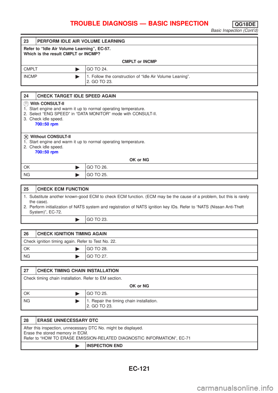
23 PERFORM IDLE AIR VOLUME LEARNING
Refer to ªIdle Air Volume Learningº, EC-57.
Which is the result CMPLT or INCMP?
CMPLT or INCMP
CMPLT©GO TO 24.
INCMP©1. Follow the construction of ªIdle Air Volume Leaningº.
2. GO TO 23.
24 CHECK TARGET IDLE SPEED AGAIN
With CONSULT-II
1. Start engine and warm it up to normal operating temperature.
2. Select ªENG SPEEDº in ªDATA MONITORº mode with CONSULT-II.
3. Check idle speed.
700±50 rpm
Without CONSULT-II
1. Start engine and warm it up to normal operating temperature.
2. Check idle speed.
700±50 rpm
OK or NG
OK©GO TO 26.
NG©GO TO 25.
25 CHECK ECM FUNCTION
1. Substitute another known-good ECM to check ECM function. (ECM may be the cause of a problem, but this is rarely
the case).
2. Perform initialization of NATS system and registration of NATS ignition key IDs. Refer to ªNATS (Nissan Anti-Theft
System)º, EC-72.
©GO TO 23.
26 CHECK IGNITION TIMING AGAIN
Check ignition timing again. Refer to Test No. 22.
OK©GO TO 28.
NG©GO TO 27.
27 CHECK TIMING CHAIN INSTALLATION
Check timing chain installation. Refer to EM section.
OK or NG
OK©GO TO 25.
NG©1. Repair the timing chain installation.
2. GO TO 23.
28 ERASE UNNECESSARY DTC
After this inspection, unnecessary DTC No. might be displayed.
Erase the stored memory in ECM.
Refer to ªHOW TO ERASE EMISSION-RELATED DIAGNOSTIC INFORMATIONº, EC-71
©INSPECTION END
TROUBLE DIAGNOSIS Ð BASIC INSPECTIONQG18DE
Basic Inspection (Cont'd)
EC-121
Page 547 of 3051
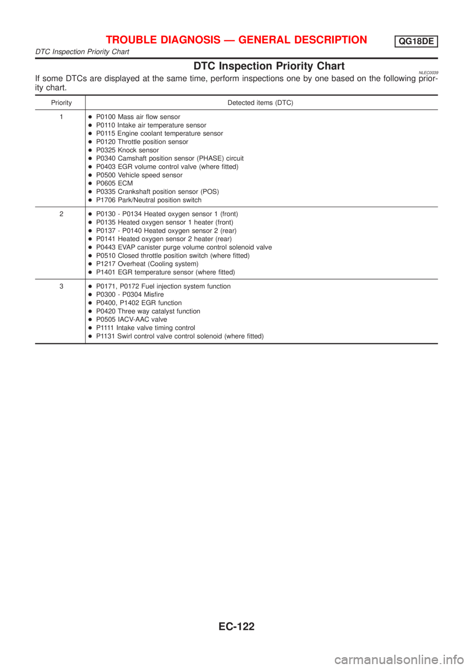
DTC Inspection Priority ChartNLEC0039If some DTCs are displayed at the same time, perform inspections one by one based on the following prior-
ity chart.
Priority Detected items (DTC)
1+P0100 Mass air flow sensor
+P0110 Intake air temperature sensor
+P0115 Engine coolant temperature sensor
+P0120 Throttle position sensor
+P0325 Knock sensor
+P0340 Camshaft position sensor (PHASE) circuit
+P0403 EGR volume control valve (where fitted)
+P0500 Vehicle speed sensor
+P0605 ECM
+P0335 Crankshaft position sensor (POS)
+P1706 Park/Neutral position switch
2+P0130 - P0134 Heated oxygen sensor 1 (front)
+P0135 Heated oxygen sensor 1 heater (front)
+P0137 - P0140 Heated oxygen sensor 2 (rear)
+P0141 Heated oxygen sensor 2 heater (rear)
+P0443 EVAP canister purge volume control solenoid valve
+P0510 Closed throttle position switch (where fitted)
+P1217 Overheat (Cooling system)
+P1401 EGR temperature sensor (where fitted)
3+P0171, P0172 Fuel injection system function
+P0300 - P0304 Misfire
+P0400, P1402 EGR function
+P0420 Three way catalyst function
+P0505 IACV-AAC valve
+P 1111Intake valve timing control
+P1131 Swirl control valve control solenoid (where fitted)
TROUBLE DIAGNOSIS Ð GENERAL DESCRIPTIONQG18DE
DTC Inspection Priority Chart
EC-122
Page 548 of 3051
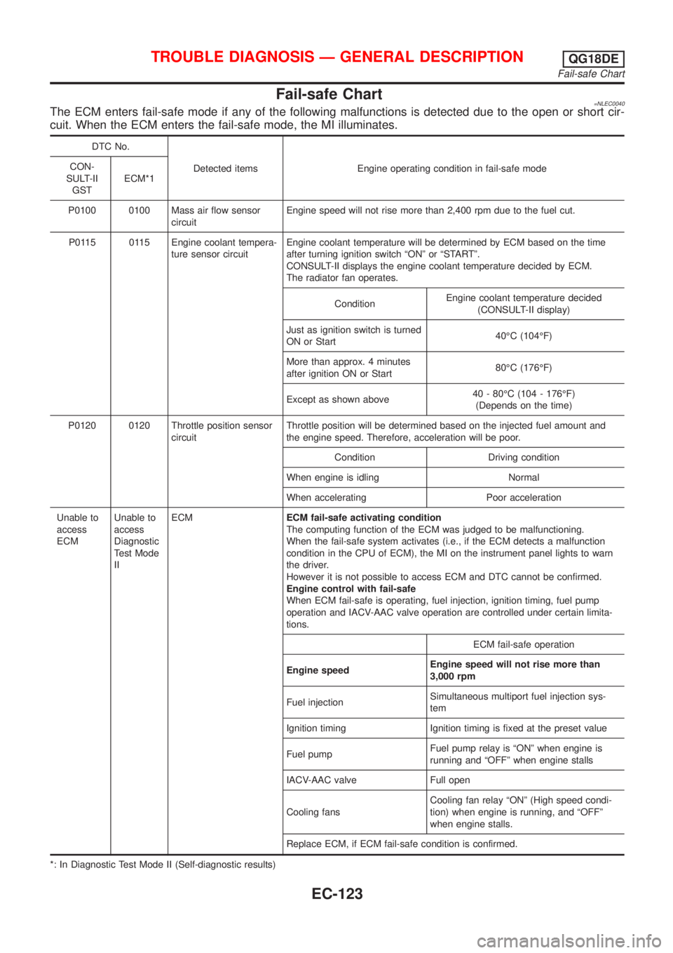
Fail-safe Chart=NLEC0040The ECM enters fail-safe mode if any of the following malfunctions is detected due to the open or short cir-
cuit. When the ECM enters the fail-safe mode, the MI illuminates.
DTC No.
Detected items Engine operating condition in fail-safe mode CON-
SULT-II
GSTECM*1
P0100 0100 Mass air flow sensor
circuitEngine speed will not rise more than 2,400 rpm due to the fuel cut.
P0115 0115 Engine coolant tempera-
ture sensor circuitEngine coolant temperature will be determined by ECM based on the time
after turning ignition switch ªONº or ªSTARTº.
CONSULT-II displays the engine coolant temperature decided by ECM.
The radiator fan operates.
ConditionEngine coolant temperature decided
(CONSULT-II display)
Just as ignition switch is turned
ON or Start40ÉC (104ÉF)
More than approx. 4 minutes
after ignition ON or Start80ÉC (176ÉF)
Except as shown above40 - 80ÉC (104 - 176ÉF)
(Depends on the time)
P0120 0120 Throttle position sensor
circuitThrottle position will be determined based on the injected fuel amount and
the engine speed. Therefore, acceleration will be poor.
Condition Driving condition
When engine is idling Normal
When accelerating Poor acceleration
Unable to
access
ECMUnable to
access
Diagnostic
Test Mode
IIECMECM fail-safe activating condition
The computing function of the ECM was judged to be malfunctioning.
When the fail-safe system activates (i.e., if the ECM detects a malfunction
condition in the CPU of ECM), the MI on the instrument panel lights to warn
the driver.
However it is not possible to access ECM and DTC cannot be confirmed.
Engine control with fail-safe
When ECM fail-safe is operating, fuel injection, ignition timing, fuel pump
operation and IACV-AAC valve operation are controlled under certain limita-
tions.
ECM fail-safe operation
Engine speedEngine speed will not rise more than
3,000 rpm
Fuel injectionSimultaneous multiport fuel injection sys-
tem
Ignition timing Ignition timing is fixed at the preset value
Fuel pumpFuel pump relay is ªONº when engine is
running and ªOFFº when engine stalls
IACV-AAC valve Full open
Cooling fansCooling fan relay ªONº (High speed condi-
tion) when engine is running, and ªOFFº
when engine stalls.
Replace ECM, if ECM fail-safe condition is confirmed.
*: In Diagnostic Test Mode II (Self-diagnostic results)
TROUBLE DIAGNOSIS Ð GENERAL DESCRIPTIONQG18DE
Fail-safe Chart
EC-123
Page 553 of 3051

CONSULT-II Reference Value in Data Monitor
Mode
NLEC0042Remarks:
+Specification data are reference values.
+Specification data are output/input values which are detected or supplied by the ECM at the connector.
* Specification data may not be directly related to their components signals/values/operations.
(i.e., Adjust ignition timing with a timing light before monitoring IGN TIMING. Specification data might be displayed even when igni-
tion timing is not adjusted to specification. This IGN TIMING monitors the data calculated by the ECM according to the input signals
from the crankshaft position sensor and other ignition timing related sensors.)
+If the real-time diagnosis results are NG, and the on board diagnostic system results are OK, when diagnosing the mass air flow sensor,
first check to see if the fuel pump control circuit is normal.
MONITOR ITEM CONDITION SPECIFICATION
ENG SPEED+Tachometer: Connect
+Run engine and compare tachometer indication with the CONSULT-II
value.Almost the same speed as the
CONSULT-II value.
MAS A/F SE-B1+Engine: After warming up
+Air conditioner switch: OFF
+Shift lever: ªNº
+No-loadIdle 1.0 - 1.7V
2,500 rpm 1.5 - 2.1V
B/FUEL SCHDL+Engine: After warming up
+Air conditioner switch: OFF
+Shift lever: ªNº
+No-loadIdle 1.5 - 3.0 msec
2,000 rpm 1.2 - 3.0 msec
A/F ALPHA-B1+Engine: After warming upMaintaining engine speed at 2,000
rpm75 - 125%
COOLAN TEMP/S+Engine: After warming up More than 70ÉC (158ÉF)
HO2S1 (B1)
+Engine: After warming upMaintaining engine speed at 2,000
rpm0 - 0.3V¨0.6 - 1.0V
HO2S1 MNTR (B1)LEAN¨RICH
Changes more than 5 times
during 10 seconds.
HO2S2 (B1)
+Engine: After warming upRevving engine from idle to 3,000
rpm quickly0 - 0.3V¨0.6 - 1.0V
HO2S2 MNTR (B1)LEAN¨RICH
VHCL SPEED SE+Turn drive wheels and compare speedometer indication with the CON-
SULT-II valueAlmost the same speed as the
CONSULT-II value
BATTERY VOLT+Ignition switch: ON (Engine stopped) 11 - 14V
THRTL POS SEN+Engine: Idle Throttle valve fully closed 0.15 - 0.85V
+Ignition switch: ON
(Engine stopped)Throttle valve fully opened 3.5 - 4.7V
EGR TEMP SEN
(where fitted)+Engine: After warming up Less than 4.5V
START SIGNAL+Ignition switch: ON®START®ON OFF®ON®OFF
CLSD THL POS
CLSD THL/P SW
(where fitted)+Engine: Idle
Throttle valve: Idle position ON
+Ignition switch: ON
(Engine stopped)Throttle valve: Slightly open OFF
AIR COND SIG+Engine: After warming up, idle
the engineA/C switch ªOFFº OFF
A/C switch ªONº
(Compressor operates)ON
P/N POSI SW+Ignition switch: ONShift lever ªPº or ªNº ON
Except above OFF
TROUBLE DIAGNOSIS Ð GENERAL DESCRIPTIONQG18DE
CONSULT-II Reference Value in Data Monitor Mode
EC-128
Page 566 of 3051
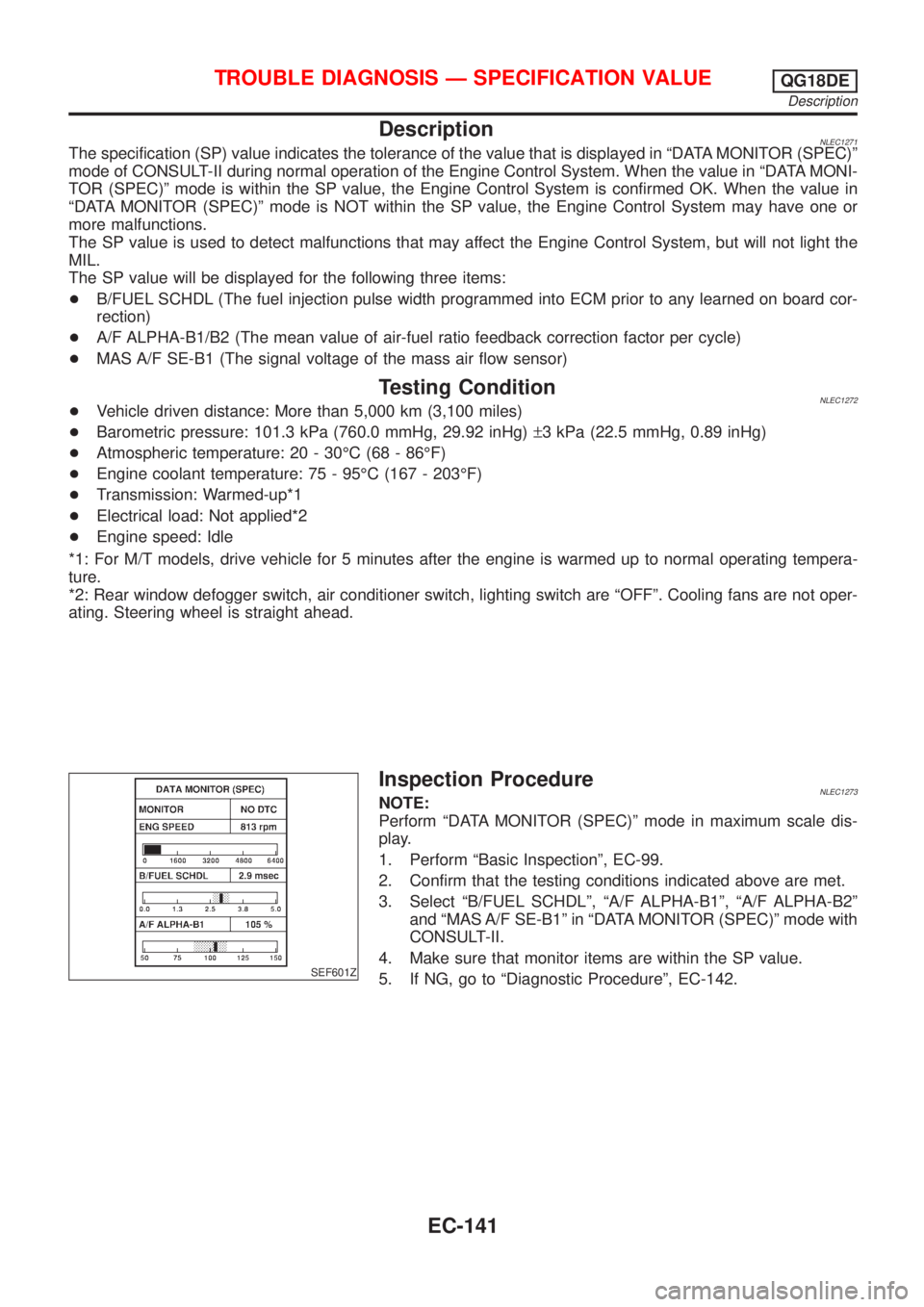
DescriptionNLEC1271The specification (SP) value indicates the tolerance of the value that is displayed in ªDATA MONITOR (SPEC)º
mode of CONSULT-II during normal operation of the Engine Control System. When the value in ªDATA MONI-
TOR (SPEC)º mode is within the SP value, the Engine Control System is confirmed OK. When the value in
ªDATA MONITOR (SPEC)º mode is NOT within the SP value, the Engine Control System may have one or
more malfunctions.
The SP value is used to detect malfunctions that may affect the Engine Control System, but will not light the
MIL.
The SP value will be displayed for the following three items:
+B/FUEL SCHDL (The fuel injection pulse width programmed into ECM prior to any learned on board cor-
rection)
+A/F ALPHA-B1/B2 (The mean value of air-fuel ratio feedback correction factor per cycle)
+MAS A/F SE-B1 (The signal voltage of the mass air flow sensor)
Testing ConditionNLEC1272+Vehicle driven distance: More than 5,000 km (3,100 miles)
+Barometric pressure: 101.3 kPa (760.0 mmHg, 29.92 inHg)±3 kPa (22.5 mmHg, 0.89 inHg)
+Atmospheric temperature: 20 - 30ÉC (68 - 86ÉF)
+Engine coolant temperature: 75 - 95ÉC (167 - 203ÉF)
+Transmission: Warmed-up*1
+Electrical load: Not applied*2
+Engine speed: Idle
*1: For M/T models, drive vehicle for 5 minutes after the engine is warmed up to normal operating tempera-
ture.
*2: Rear window defogger switch, air conditioner switch, lighting switch are ªOFFº. Cooling fans are not oper-
ating. Steering wheel is straight ahead.
SEF601Z
Inspection ProcedureNLEC1273NOTE:
Perform ªDATA MONITOR (SPEC)º mode in maximum scale dis-
play.
1. Perform ªBasic Inspectionº, EC-99.
2. Confirm that the testing conditions indicated above are met.
3. Select ªB/FUEL SCHDLº, ªA/F ALPHA-B1º, ªA/F ALPHA-B2º
and ªMAS A/F SE-B1º in ªDATA MONITOR (SPEC)º mode with
CONSULT-II.
4. Make sure that monitor items are within the SP value.
5. If NG, go to ªDiagnostic Procedureº, EC-142.
TROUBLE DIAGNOSIS Ð SPECIFICATION VALUEQG18DE
Description
EC-141
Page 595 of 3051
Fail-safe ModeNLEC0566
Detected items Engine operating condition in fail-safe mode
Engine coolant tempera-
ture sensor circuitEngine coolant temperature will be determined by ECM based on the time after turning ignition switch
ªONº or ªSTARTº.
CONSULT-II displays the engine coolant temperature decided by ECM.
ConditionEngine coolant temperature decided (CONSULT-II
display)
Just as ignition switch is turned ON or Start 40ÉC (104ÉF)
More than approx. 4 minutes after ignition ON or
Start80ÉC (176ÉF)
Except as shown above40 - 80ÉC (104 - 176ÉF)
(Depends on the time)
When the fail-safe system for engine coolant temperature sensor is activated, the cooling fan operates
while the engine is running.
SEF013Y
DTC Confirmation ProcedureNLEC0075NOTE:
If ªDTC Confirmation Procedureº has been previously conducted,
always turn ignition switch ªOFFº and wait at least 9 seconds
before conducting the next test.
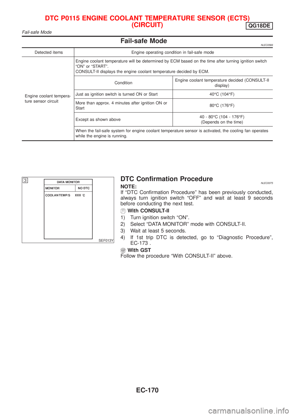
With CONSULT-II
1) Turn ignition switch ªONº.
2) Select ªDATA MONITORº mode with CONSULT-II.
3) Wait at least 5 seconds.
4) If 1st trip DTC is detected, go to ªDiagnostic Procedureº,
EC-173 .
With GST
Follow the procedure ªWith CONSULT-IIº above.
DTC P0115 ENGINE COOLANT TEMPERATURE SENSOR (ECTS)
(CIRCUIT)
QG18DE
Fail-safe Mode
EC-170
Page 600 of 3051
Component DescriptionNLEC0079NOTE:
If DTC P0120 (0120) is displayed with DTC P0510 (0510), first perform trouble diagnosis for DTC P0510,
EC-352.
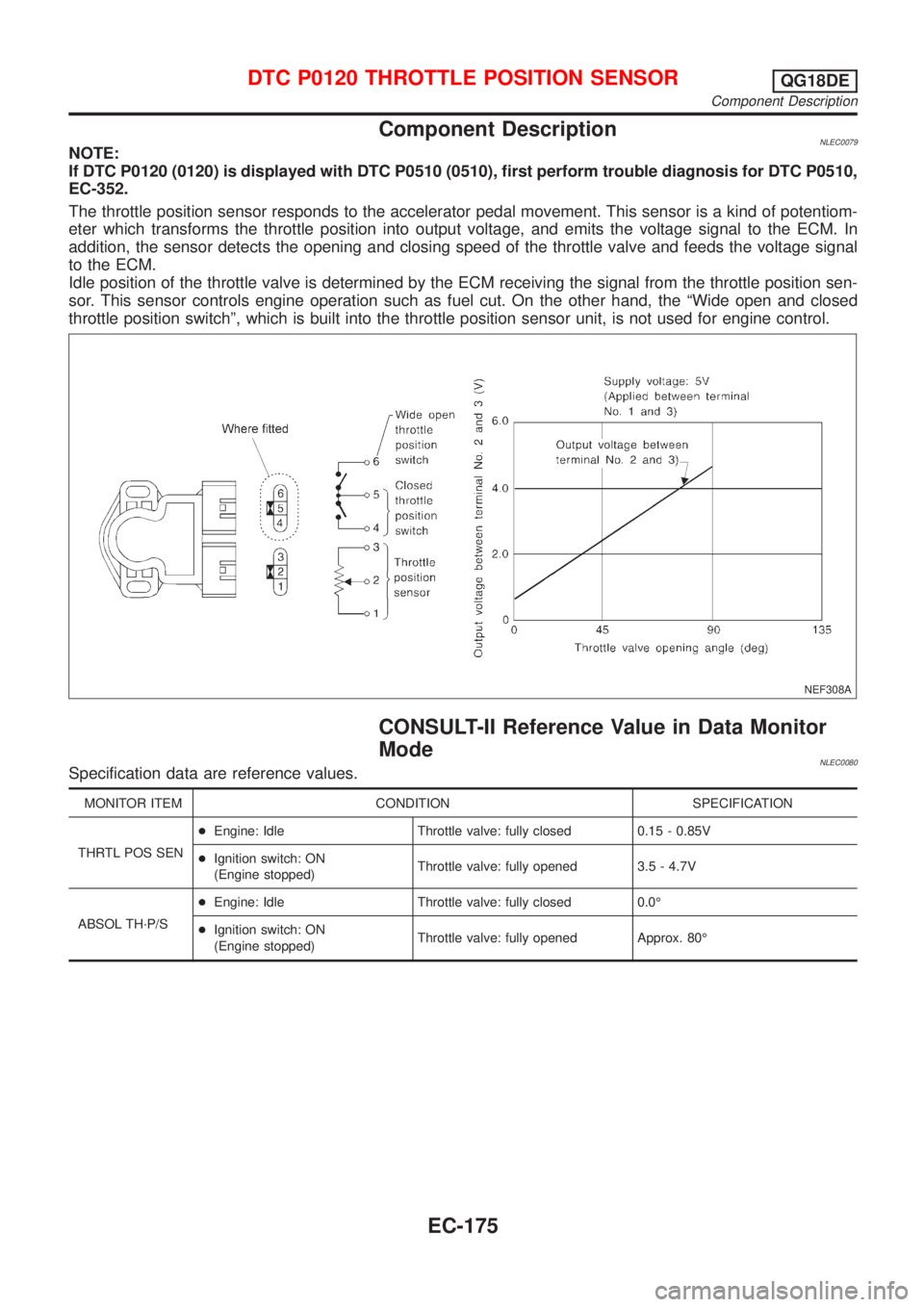
The throttle position sensor responds to the accelerator pedal movement. This sensor is a kind of potentiom-
eter which transforms the throttle position into output voltage, and emits the voltage signal to the ECM. In
addition, the sensor detects the opening and closing speed of the throttle valve and feeds the voltage signal
to the ECM.
Idle position of the throttle valve is determined by the ECM receiving the signal from the throttle position sen-
sor. This sensor controls engine operation such as fuel cut. On the other hand, the ªWide open and closed
throttle position switchº, which is built into the throttle position sensor unit, is not used for engine control.
NEF308A
CONSULT-II Reference Value in Data Monitor
Mode
NLEC0080Specification data are reference values.
MONITOR ITEM CONDITION SPECIFICATION
THRTL POS SEN+Engine: Idle Throttle valve: fully closed 0.15 - 0.85V
+Ignition switch: ON
(Engine stopped)Throttle valve: fully opened 3.5 - 4.7V
ABSOL TH´P/S+Engine: Idle Throttle valve: fully closed 0.0É
+Ignition switch: ON
(Engine stopped)Throttle valve: fully opened Approx. 80É
DTC P0120 THROTTLE POSITION SENSORQG18DE
Component Description
EC-175