Page 57 of 3051
SAT236K
10. When performing cruise test, touch ªStore Dataº.
SAT237K
11. After finishing cruise test part 1, touch ªSTOPº.
SAT254K
12. Touch ªSTOREº.
SAT608J
13. Touch ªDISPLAYº.
SAT238K
14. Touch ªPRINTº.
15. Check the monitor data printed out.
16. Continue cruise test part 2 and 3.
TROUBLE DIAGNOSIS Ð BASIC INSPECTION
Road Test (Cont'd)
AT-56
Page 126 of 3051

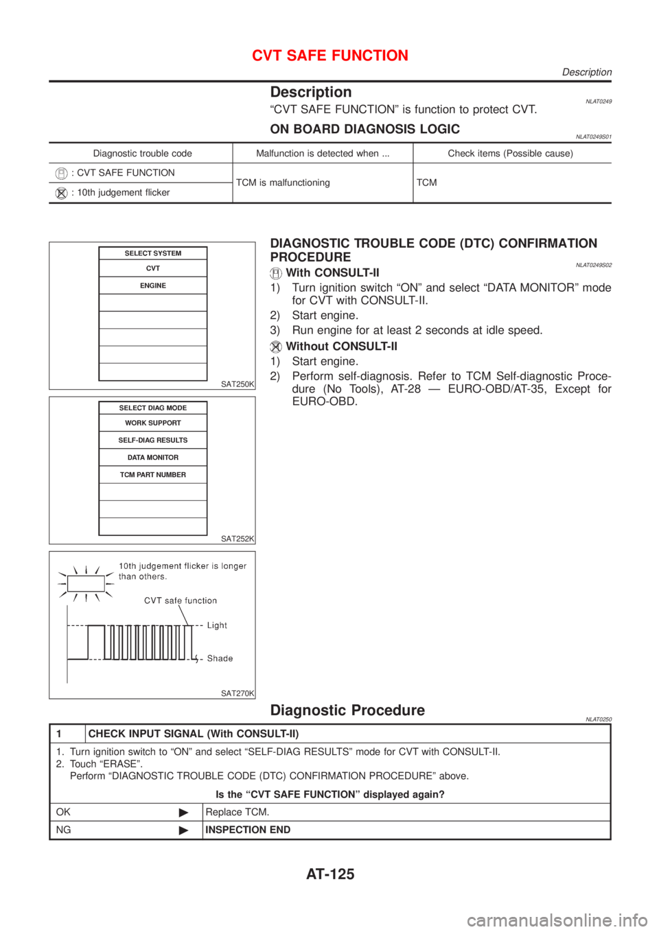
DescriptionNLAT0249ªCVT SAFE FUNCTIONº is function to protect CVT.
ON BOARD DIAGNOSIS LOGICNLAT0249S01
Diagnostic trouble code Malfunction is detected when ... Check items (Possible cause)
: CVT SAFE FUNCTION
TCM is malfunctioning TCM
: 10th judgement flicker
SAT250K
SAT252K
SAT270K
DIAGNOSTIC TROUBLE CODE (DTC) CONFIRMATION
PROCEDURE
NLAT0249S02With CONSULT-II
1) Turn ignition switch ªONº and select ªDATA MONITORº mode
for CVT with CONSULT-II.
2) Start engine.
3) Run engine for at least 2 seconds at idle speed.
Without CONSULT-II
1) Start engine.
2) Perform self-diagnosis. Refer to TCM Self-diagnostic Proce-
dure (No Tools), AT-28 Ð EURO-OBD/AT-35, Except for
EURO-OBD.
Diagnostic ProcedureNLAT0250
1 CHECK INPUT SIGNAL (With CONSULT-II)
1. Turn ignition switch to ªONº and select ªSELF-DIAG RESULTSº mode for CVT with CONSULT-II.
2. Touch ªERASEº.
Perform ªDIAGNOSTIC TROUBLE CODE (DTC) CONFIRMATION PROCEDUREº above.
Is the ªCVT SAFE FUNCTIONº displayed again?
OK©Replace TCM.
NG©INSPECTION END
CVT SAFE FUNCTION
Description
AT-125
Page 182 of 3051
Diagnostic Procedure=NLAT0289
1 CHECK DTC
With CONSULT-II
1. Turn ignition switch ªONº and select ªSELF-DIAG RESULTSº mode for CVT with CONSULT-II.
2. Touch ªERASEº.
PERFORM DIAGNOSTIC TROUBLE CODE (DTC) CONFIRMATION PROCEDURE.
See previous page.
Is the ªCONTROL UNIT (RAM) or CONTROL UNIT (ROM)º displayed again?
Ye s©Replace TCM.
No©INSPECTION END
CONTROL UNIT (RAM), CONTROL UNIT (ROM)
Diagnostic Procedure
AT-181
Page 184 of 3051
Diagnostic Procedure=NLAT0242
1 CHECK DTC
With CONSULT-II
1. Turn ignition switch ªONº and select ªSELF-DIAG RESULTSº mode for CVT with CONSULT-II.
2. Move selector lever to ªRº position.
3. Depress accelerator pedal (Full throttle position).
4. Touch ªERASEº.
5. Turn ignition switch ªOFFº position for 10 seconds.
PERFORM DIAGNOSTIC TROUBLE CODE (DTC) CONFIRMATION PROCEDURE.
See previous page.
Is the ªCONT UNIT (EEPROM)º displayed again?
Ye s©Replace TCM.
No©INSPECTION END
CONTROL UNIT (EEPROM)
Diagnostic Procedure
AT-183
Page 295 of 3051

CONSULT-IINLBR0092CONSULT-II APPLICATION TO ABSNLBR0092S01
ITEMSELF-DIAGNOSTIC
RESULTSDATA MONITOR ACTIVE TEST
Front right wheel sensor X X—
Front left wheel sensor X X—
Rear right wheel sensor X X—
Rear left wheel sensor X X—
Stop lamp switch—X—
Front right inlet solenoid valve X X X
Front right outlet solenoid valve X X X
Front left inlet solenoid valve X X X
Front left outlet solenoid valve X X X
Rear right inlet solenoid valve X X X
Rear right outlet solenoid valve X X X
Rear left inlet solenoid valve X X X
Rear left outlet solenoid valve X X X
Actuator solenoid valve relay X X—
Actuator motor relay
(ABS MOTOR is shown on the ACTIVE TEST
screen.)XXX
ABS warning lamp—X—
Battery voltage X X—
Control unit X——
X: Applicable
—: Not applicable
ECU (ABS CONTROL UNIT) PART NUMBER MODENLBR0092S02Ignore the ECU part number displayed in the ECU PART NUMBER MODE. Refer to parts catalog to order
the ABS actuator and electric unit.
NBR371
CONSULT-II Inspection ProcedureNLBR0093SELF-DIAGNOSIS PROCEDURENLBR0093S011. Turn ignition switch OFF.
2. Connect CONSULT-II to data link connector.
3. Start engine.
4. Drive vehicle over 30 km/h (19 MPH) for at least one minute.
ON BOARD DIAGNOSTIC SYSTEM DESCRIPTIONABS
CONSULT-II
BR-58
Page 300 of 3051

DATA MONITOR MODENLBR0093S05
MONITOR ITEM CONDITION SPECIFICATION
FR RH SENSOR
FR LH SENSOR
RR RH SENSOR
RR LH SENSORDrive vehicle.
(Each wheel is rotating.)Displays computed vehicle speed from wheel sensor signal.
Almost the same speed as speedometer.
STOP LAMP SWTurn ignition switch ON and
depress brake pedal.Depress the pedal: ON
Release the pedal: OFF
FR RH IN SOL
FR RH OUT SOL
FR LH IN SOL
FR LH OUT SOL
RR IN SOL
RR OUT SOL
RL IN SOL
RL OUT SOLIgnition switch is turned ON or
engine is running.Operating conditions for each solenoid valve are indicated.
ABS is not operating: OFF
ACTUATOR RELAY
Ignition switch is turned ON or
engine is running.Displays ON/OFF condition of ABS actuator relay.
When turning ignition switch ON, ABS actuator relay is oper-
ated.
MOTOR RELAYABS is not operating: OFF
ABS is operating: ON
WARNING LAMPWarning lamp is turned on: ON
Warning lamp is turned off: OFF
BATTERY VOLT Power supply voltage for control unit
ACTIVE TEST MODENLBR0093S06
TEST ITEM CONDITION JUDGEMENT
FR RH SOLENOID
FR LH SOLENOID
RR RH SOLENOID
RR LH SOLENOID
Ignition switch is turned ON.Brake fluid pressure control operation
IN SOL OUT SOL
UP (Increase): OFF OFF
KEEP (Hold): ON OFF
DOWN (Decrease): ON ON
ABS MOTORABS actuator motor
ON: Motor runs
OFF: Motor stops
NOTE:
Active test will automatically stop ten seconds after the test starts. (TEST IS STOPPED monitor shows ON.)
ON BOARD DIAGNOSTIC SYSTEM DESCRIPTIONABS
CONSULT-II Inspection Procedure (Cont’d)
BR-63
Page 448 of 3051

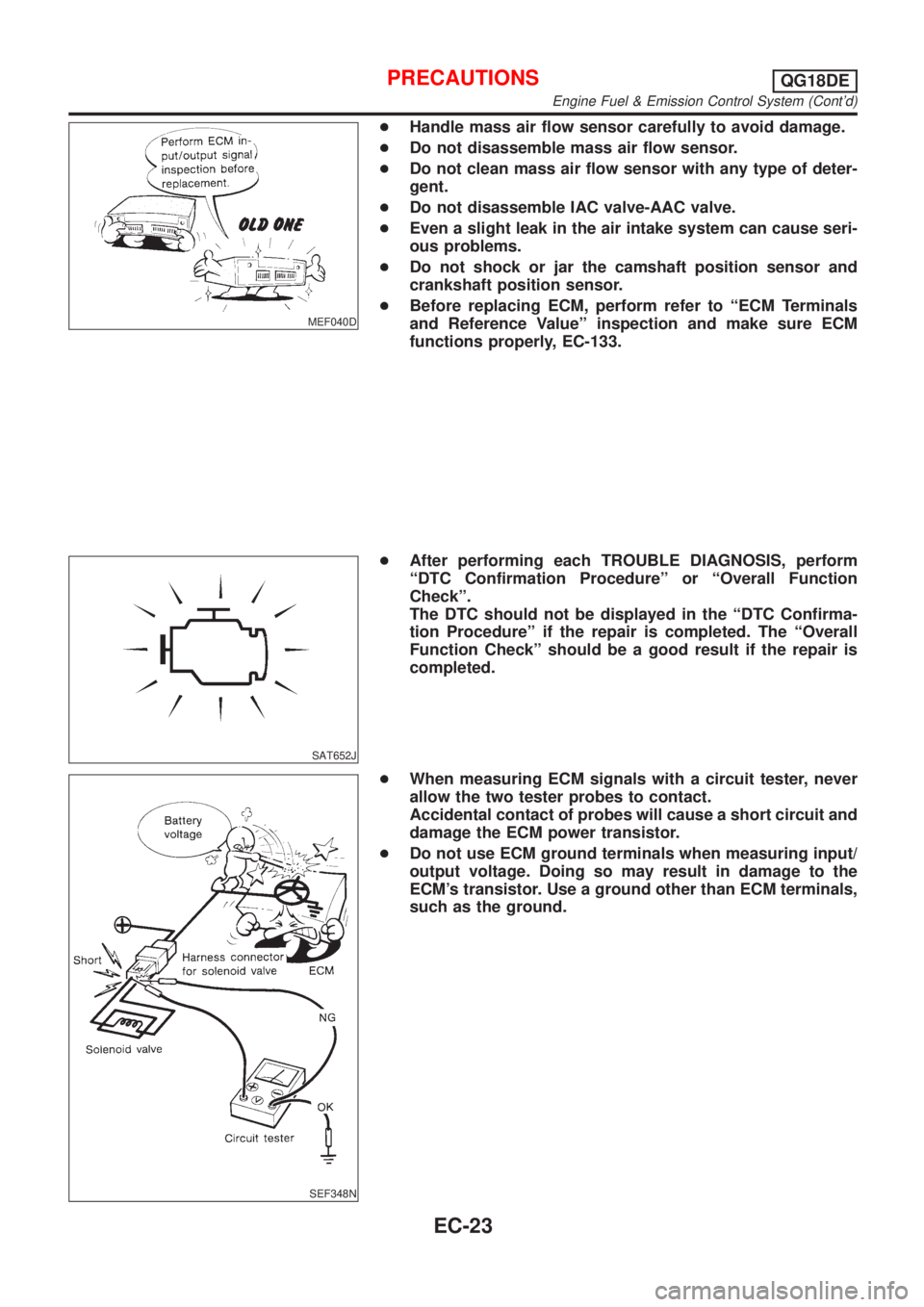
MEF040D
+Handle mass air flow sensor carefully to avoid damage.
+Do not disassemble mass air flow sensor.
+Do not clean mass air flow sensor with any type of deter-
gent.
+Do not disassemble IAC valve-AAC valve.
+Even a slight leak in the air intake system can cause seri-
ous problems.
+Do not shock or jar the camshaft position sensor and
crankshaft position sensor.
+Before replacing ECM, perform refer to ªECM Terminals
and Reference Valueº inspection and make sure ECM
functions properly, EC-133.
SAT652J
+After performing each TROUBLE DIAGNOSIS, perform
ªDTC Confirmation Procedureº or ªOverall Function
Checkº.
The DTC should not be displayed in the ªDTC Confirma-
tion Procedureº if the repair is completed. The ªOverall
Function Checkº should be a good result if the repair is
completed.
SEF348N
+When measuring ECM signals with a circuit tester, never
allow the two tester probes to contact.
Accidental contact of probes will cause a short circuit and
damage the ECM power transistor.
+Do not use ECM ground terminals when measuring input/
output voltage. Doing so may result in damage to the
ECM's transistor. Use a ground other than ECM terminals,
such as the ground.
PRECAUTIONSQG18DE
Engine Fuel & Emission Control System (Cont'd)
EC-23
Page 474 of 3051
Inspection ProcedureNLEC0593
1 INSPECTION START
1. Visually check the following:
+Air cleaner clogging
+Hoses and ducts for leaks
+EGR valve operation
+Electrical connectors
+Gasket
+Throttle valve and throttle position sensor operation
2. Start engine and warm it up until engine coolant temperature indicator points to the middle of gauge.
Ensure engine stays below 1,000 rpm.
SEF090Y
3. Open engine hood and run engine at about 2,000 rpm for about 2 minutes under no-load.
SEF977U
4. Make sure that no DTC is displayed with CONSULT-II, GST or without CONSULT-II (Method refers to EC-75.)
OK or NG
OK©GO TO 3.
NG©GO TO 2.
2 REPAIR OR REPLACE
Repair or replace components as necessary according to corresponding ªDiagnostic Procedureº.
©GO TO 3.
BASIC SERVICE PROCEDUREQG18DE
Inspection Procedure
EC-49