2001 NISSAN ALMERA TINO oil level
[x] Cancel search: oil levelPage 2799 of 3051
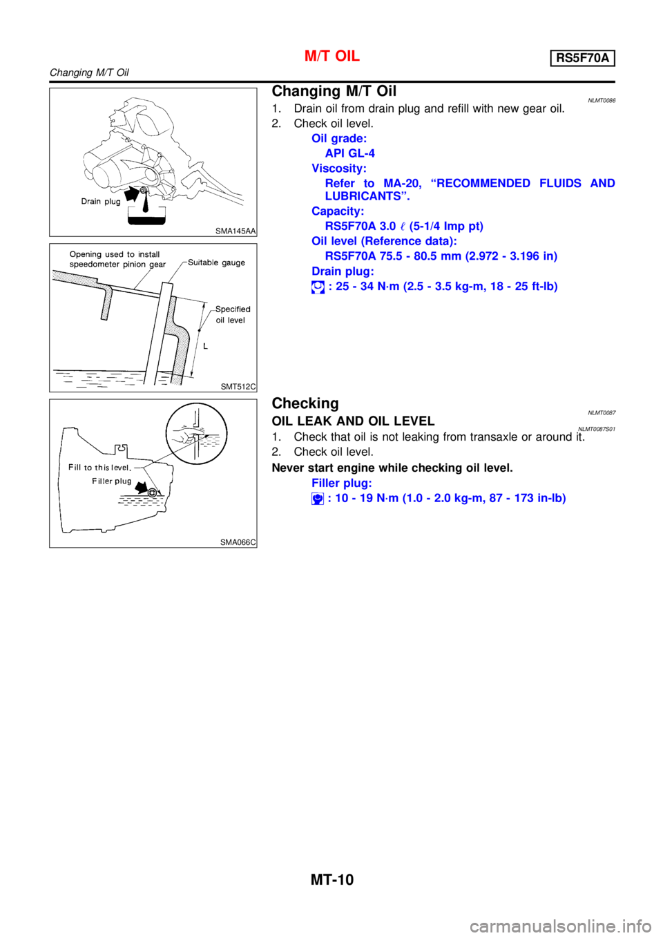
SMA145AA
SMT512C
Changing M/T OilNLMT00861. Drain oil from drain plug and refill with new gear oil.
2. Check oil level.
Oil grade:
API GL-4
Viscosity:
Refer to MA-20,“RECOMMENDED FLUIDS AND
LUBRICANTS”.
Capacity:
RS5F70A 3.0!(5-1/4 Imp pt)
Oil level (Reference data):
RS5F70A 75.5 - 80.5 mm (2.972 - 3.196 in)
Drain plug:
:25-34N·m (2.5 - 3.5 kg-m, 18 - 25 ft-lb)
SMA066C
CheckingNLMT0087OIL LEAK AND OIL LEVELNLMT0087S011. Check that oil is not leaking from transaxle or around it.
2. Check oil level.
Never start engine while checking oil level.
Filler plug:
:10-19N·m (1.0 - 2.0 kg-m, 87 - 173 in-lb)
M/T OILRS5F70A
Changing M/T Oil
MT-10
Page 2800 of 3051
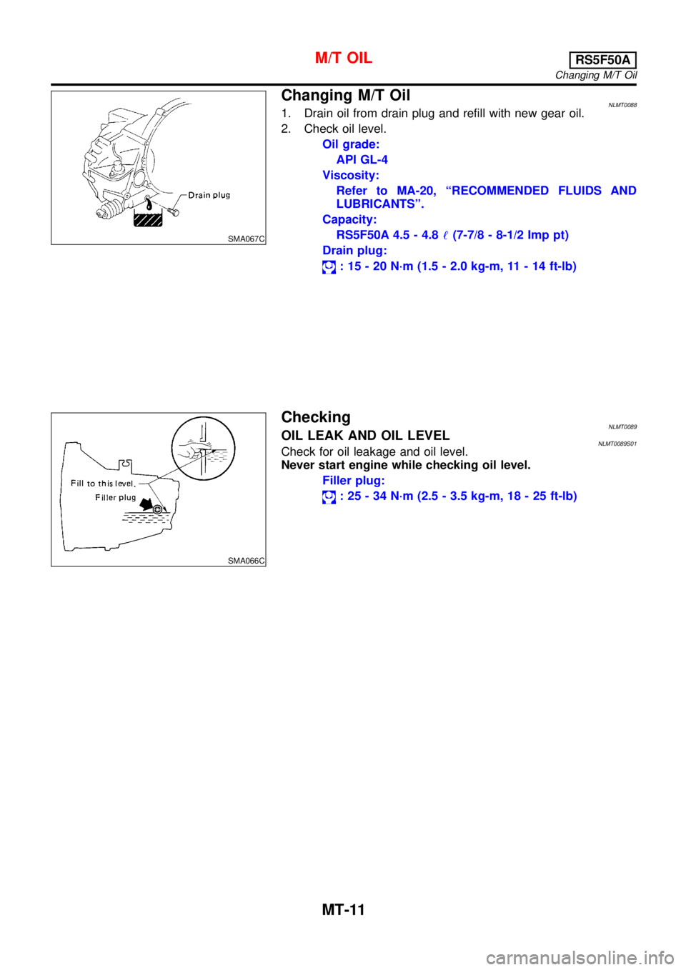
SMA067C
Changing M/T OilNLMT00881. Drain oil from drain plug and refill with new gear oil.
2. Check oil level.
Oil grade:
API GL-4
Viscosity:
Refer to MA-20,“RECOMMENDED FLUIDS AND
LUBRICANTS”.
Capacity:
RS5F50A 4.5 - 4.8!(7-7/8 - 8-1/2 Imp pt)
Drain plug:
:15-20N·m (1.5 - 2.0 kg-m, 11 - 14 ft-lb)
SMA066C
CheckingNLMT0089OIL LEAK AND OIL LEVELNLMT0089S01Check for oil leakage and oil level.
Never start engine while checking oil level.
Filler plug:
:25-34N·m (2.5 - 3.5 kg-m, 18 - 25 ft-lb)
M/T OILRS5F50A
Changing M/T Oil
MT-11
Page 2877 of 3051
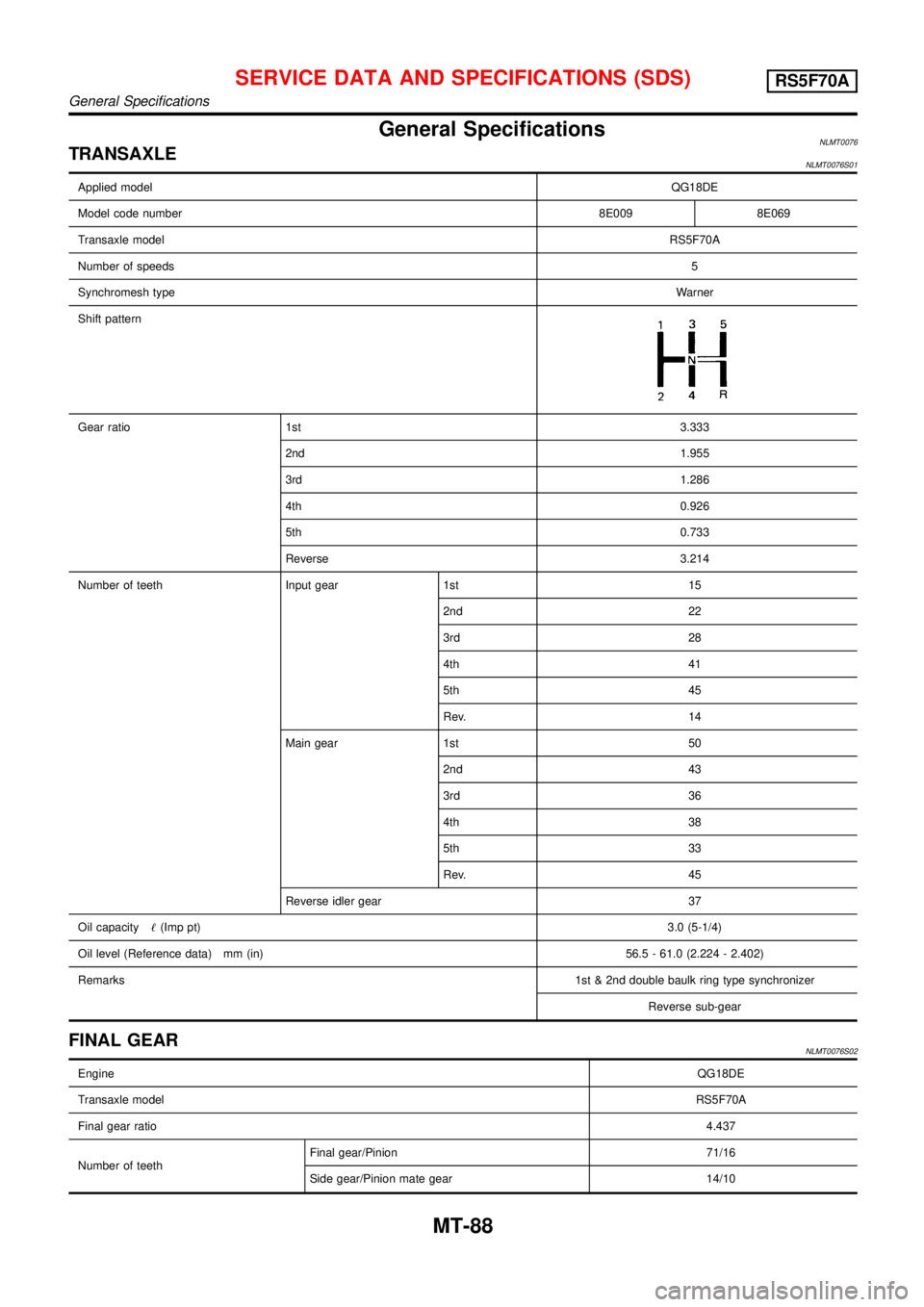
General SpecificationsNLMT0076TRANSAXLENLMT0076S01
Applied modelQG18DE
Model code number8E009 8E069
Transaxle modelRS5F70A
Number of speeds5
Synchromesh typeWarner
Shift pattern
Gear ratio 1st3.333
2nd1.955
3rd1.286
4th0.926
5th0.733
Reverse 3.214
Number of teeth Input gear 1st 15
2nd 22
3rd 28
4th 41
5th 45
Rev. 14
Main gear 1st 50
2nd 43
3rd 36
4th 38
5th 33
Rev. 45
Reverse idler gear 37
Oil capacity!(Imp pt)3.0 (5-1/4)
Oil level (Reference data) mm (in) 56.5 - 61.0 (2.224 - 2.402)
Remarks1st & 2nd double baulk ring type synchronizer
Reverse sub-gear
FINAL GEARNLMT0076S02
EngineQG18DE
Transaxle modelRS5F70A
Final gear ratio4.437
Number of teethFinal gear/Pinion 71/16
Side gear/Pinion mate gear 14/10
SERVICE DATA AND SPECIFICATIONS (SDS)RS5F70A
General Specifications
MT-88
Page 2996 of 3051
STEERING SYSTEM
SECTION
ST
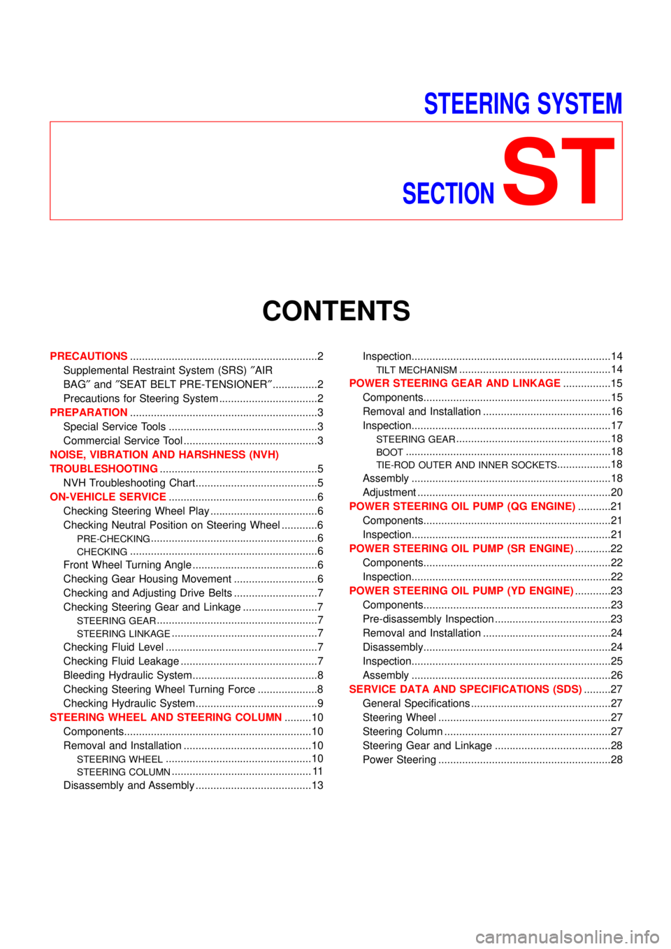
CONTENTS
PRECAUTIONS...............................................................2
Supplemental Restraint System (SRS)″AIR
BAG″and″SEAT BELT PRE-TENSIONER″...............2
Precautions for Steering System .................................2
PREPARATION...............................................................3
Special Service Tools ..................................................3
Commercial Service Tool .............................................3
NOISE, VIBRATION AND HARSHNESS (NVH)
TROUBLESHOOTING.....................................................5
NVH Troubleshooting Chart.........................................5
ON-VEHICLE SERVICE..................................................6
Checking Steering Wheel Play ....................................6
Checking Neutral Position on Steering Wheel ............6
PRE-CHECKING........................................................6
CHECKING...............................................................6
Front Wheel Turning Angle ..........................................6
Checking Gear Housing Movement ............................6
Checking and Adjusting Drive Belts ............................7
Checking Steering Gear and Linkage .........................7
STEERING GEAR......................................................7
STEERING LINKAGE.................................................7
Checking Fluid Level ...................................................7
Checking Fluid Leakage ..............................................7
Bleeding Hydraulic System..........................................8
Checking Steering Wheel Turning Force ....................8
Checking Hydraulic System.........................................9
STEERING WHEEL AND STEERING COLUMN.........10
Components...............................................................10
Removal and Installation ...........................................10
STEERING WHEEL.................................................10
STEERING COLUMN............................................... 11
Disassembly and Assembly .......................................13Inspection...................................................................14
TILT MECHANISM...................................................14
POWER STEERING GEAR AND LINKAGE................15
Components...............................................................15
Removal and Installation ...........................................16
Inspection...................................................................17
STEERING GEAR....................................................18
BOOT.....................................................................18
TIE-ROD OUTER AND INNER SOCKETS..................18
Assembly ...................................................................18
Adjustment .................................................................20
POWER STEERING OIL PUMP (QG ENGINE)...........21
Components...............................................................21
Inspection...................................................................21
POWER STEERING OIL PUMP (SR ENGINE)............22
Components...............................................................22
Inspection...................................................................22
POWER STEERING OIL PUMP (YD ENGINE)............23
Components...............................................................23
Pre-disassembly Inspection .......................................23
Removal and Installation ...........................................24
Disassembly...............................................................24
Inspection...................................................................25
Assembly ...................................................................26
SERVICE DATA AND SPECIFICATIONS (SDS).........27
General Specifications ...............................................27
Steering Wheel ..........................................................27
Steering Column ........................................................27
Steering Gear and Linkage .......................................28
Power Steering ..........................................................28
Page 3002 of 3051

Checking and Adjusting Drive BeltsNLST0011Refer to EM-17,“Checking Drive Belts”.
SMA851B
Checking Steering Gear and LinkageNLST0037STEERING GEARNLST0037S01+Check gear housing and boots for looseness, damage or
grease leakage.
+Check connection with steering column for looseness.
STEERING LINKAGENLST0037S02+Check ball joint, dust cover and other component parts for
looseness, wear, damage or grease leakage.
YST003
Checking Fluid LevelNLST0012Check fluid level, referring to the scale on reservoir tank.
Use“HOT”range for fluid temperatures of 50 to 80°C (122 to
176°F).
Use“COLD”range for fluid temperatures of 0 to 30°C (32 to 86°F).
CAUTION:
+Do not overfill.
+Recommended fluid is DEXRON
TMIII or equivalent. Refer
to MA-20,“Fluids and Lubricants”.
YST004
YST005
Checking Fluid LeakageNLST0013Check the lines for improper attachment and for leaks, cracks,
damage, loose connections, chafing and deterioration.
1. Run engine between idle speed and 1,000 rpm.
Make sure temperature of fluid in oil tank rises to 60 to 80°C
(140 to 176°F).
2. Turn steering wheel right-to-left several times.
3. Hold steering wheel at each“lock”position for five seconds
and carefully check for fluid leakage.
CAUTION:
Do not hold the steering wheel in a locked position for more
than 15 seconds.
4. If fluid leakage at connectors is noticed, loosen flare nut and
then retighten.
Do not overtighten connector as this can damage O-ring,
washer and connector.
5. If fluid leakage from power steering pump is noticed, check
power steering pump. Refer to ST-21.
6. Check rack boots for accumulation of power steering fluid.
ON-VEHICLE SERVICE
Checking and Adjusting Drive Belts
ST-7
Page 3003 of 3051
Bleeding Hydraulic SystemNLST00141. Raise front end of vehicle until wheels are clear of the ground.
2. Add fluid into oil tank to specified level. Then quickly turn steer-
ing wheel fully to right and left and lightly touch steering stop-
pers.
Repeat steering wheel operation until fluid level no longer
decreases.
3. Start engine.
Repeat step 2. above.
+Incomplete air bleeding will cause the following to occur. When
this happens, bleed air again.
a) Air bubbles in reservoir tank
b) Clicking noise in oil pump
c) Excessive buzzing in oil pump
Fluid noise may occur in the valve or oil pump. This is common
when the vehicle is stationary or while turning the steering wheel
slowly. This does not affect the performance or durability of the
system.
SST491B
SST090B
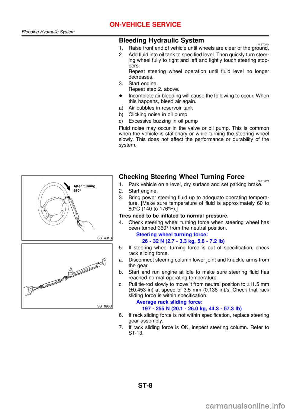
Checking Steering Wheel Turning ForceNLST00151. Park vehicle on a level, dry surface and set parking brake.
2. Start engine.
3. Bring power steering fluid up to adequate operating tempera-
ture. [Make sure temperature of fluid is approximately 60 to
80°C (140 to 176°F).]
Tires need to be inflated to normal pressure.
4. Check steering wheel turning force when steering wheel has
been turned 360°from the neutral position.
Steering wheel turning force:
26 - 32 N (2.7 - 3.3 kg, 5.8 - 7.2 lb)
5. If steering wheel turning force is out of specification, check
rack sliding force.
a. Disconnect steering column lower joint and knuckle arms from
the gear.
b. Start and run engine at idle to make sure steering fluid has
reached normal operating temperature.
c. Pull tie-rod slowly to move it from neutral position to±11.5 mm
(±0.453 in) at speed of 3.5 mm (0.138 in)/s. Check that rack
sliding force is within specification.
Average rack sliding force:
197 - 255 N (20.1 - 26.0 kg, 44.3 - 57.3 lb)
6. If rack sliding force is not within specification, replace steering
gear assembly.
7. If rack sliding force is OK, inspect steering column. Refer to
ST-13.
ON-VEHICLE SERVICE
Bleeding Hydraulic System
ST-8
Page 3029 of 3051
SMA525A
On-vehicle Service
FRONT SUSPENSION PARTSNLSU0006Check front axle and front suspension parts for excessive play,
cracks, wear or other damage.
+Shake each front wheel to check for excessive play.
+Make sure that cotter pin is inserted.
+Retighten all axle and suspension nuts and bolts to the speci-
fied torque.
Tightening torque:
Refer to “FRONT SUSPENSION”, SU-5.
SFA392B
+Check strut (shock absorber) for oil leakage or other damage.
+Check suspension ball joint for grease leakage and ball joint
dust cover for cracks or other damage.
If ball joint dust cover is cracked or damaged, replace trans-
verse link.
SFA818AA
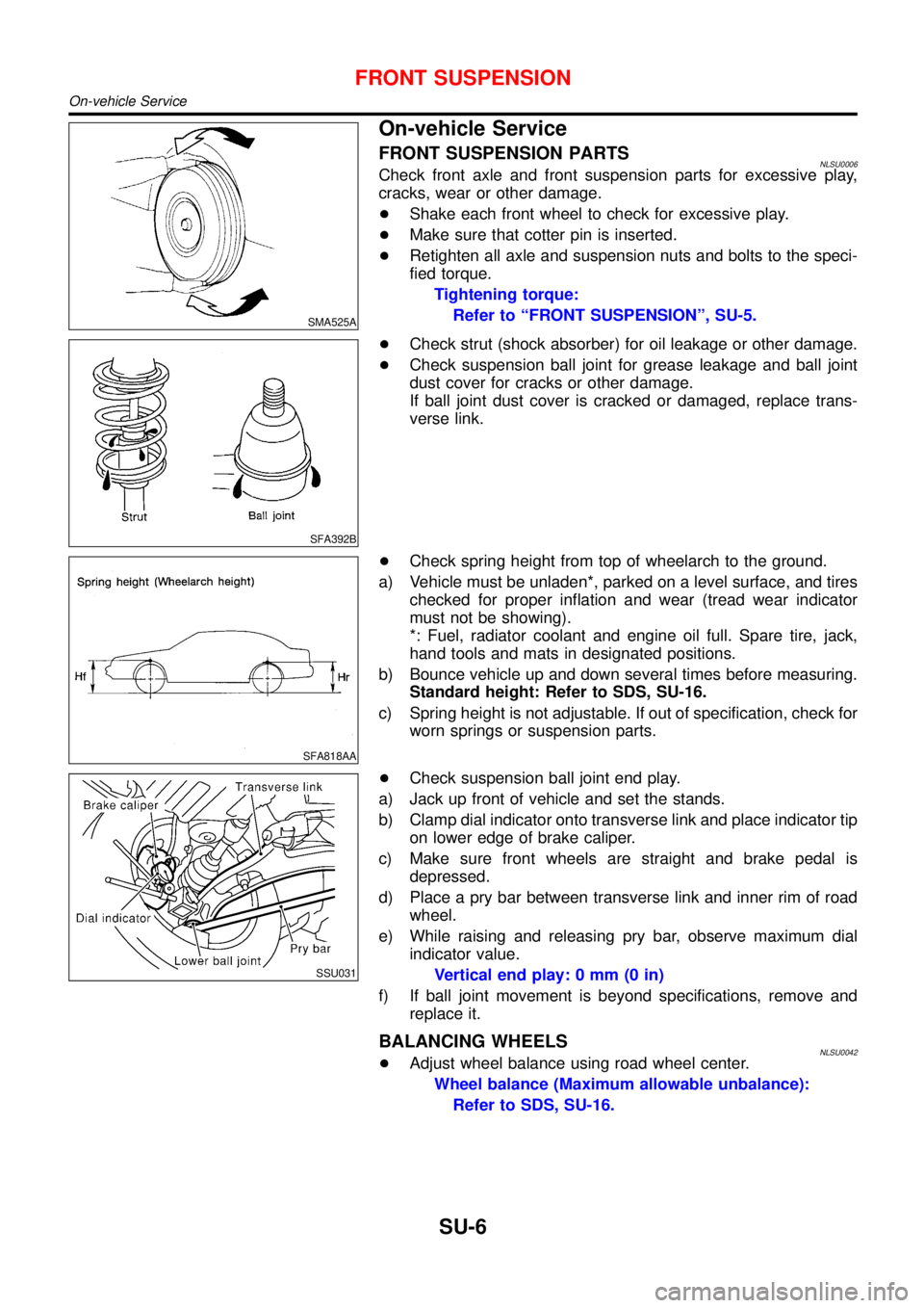
+Check spring height from top of wheelarch to the ground.
a) Vehicle must be unladen*, parked on a level surface, and tires
checked for proper inflation and wear (tread wear indicator
must not be showing).
*: Fuel, radiator coolant and engine oil full. Spare tire, jack,
hand tools and mats in designated positions.
b) Bounce vehicle up and down several times before measuring.
Standard height: Refer to SDS, SU-16.
c) Spring height is not adjustable. If out of specification, check for
worn springs or suspension parts.
SSU031
+Check suspension ball joint end play.
a) Jack up front of vehicle and set the stands.
b) Clamp dial indicator onto transverse link and place indicator tip
on lower edge of brake caliper.
c) Make sure front wheels are straight and brake pedal is
depressed.
d) Place a pry bar between transverse link and inner rim of road
wheel.
e) While raising and releasing pry bar, observe maximum dial
indicator value.
Vertical end play: 0 mm (0 in)
f) If ball joint movement is beyond specifications, remove and
replace it.
BALANCING WHEELSNLSU0042+Adjust wheel balance using road wheel center.
Wheel balance (Maximum allowable unbalance):
Refer to SDS, SU-16.
FRONT SUSPENSION
On-vehicle Service
SU-6