2001 NISSAN ALMERA TINO oil level
[x] Cancel search: oil levelPage 891 of 3051
DescriptionNLEC1305SYSTEM DESCRIPTIONNLEC1305S01
Sensor Input Signal to ECMECM func-
tionActuator
Crankshaft position sensor (POS) Engine speed
Idle air
controlIACV-AAC valve Camshaft position sensor (PHASE) Engine speed and cylinder number
Engine coolant temperature sensor Engine coolant temperature
Ignition switch Start signal
Throttle position sensor Throttle position
PNP switch Park/Neutral position
Air conditioner switch Air conditioner operation
Power steering oil pressure switch Power steering load signal
Battery Battery voltage
Vehicle speed sensor Vehicle speed
Cooling fan Cooling fan operation
Electrical load Electrical load signal
This system automatically controls engine idle speed to a specified
level. Idle speed is controlled through fine adjustment of the
amount of air which by-passes the throttle valve via IACV-AAC
valve. The IACV-AAC valve changes the opening of the air by-pass
passage to control the amount of auxiliary air. This valve is actu-
ated by a step motor built into the valve, which moves the valve in
the axial direction in steps corresponding to the ECM output sig-
nals. One step of IACV-AAC valve movement causes the respec-
tive opening of the air by-pass passage. (i.e. when the step
advances, the opening is enlarged.) The opening of the valve is
varied to allow for optimum control of the engine idling speed. The
crankshaft position sensor (POS) detects the actual engine speed
and sends a signal to the ECM. The ECM then controls the step
position of the IACV-AAC valve so that engine speed coincides with
the target value memorized in ECM. The target engine speed is the
lowest speed at which the engine can operate steadily. The opti-
mum value stored in the ECM is determined by taking into consid-
eration various engine conditions, such as during warm up,
deceleration, and engine load (air conditioner, power steering, cool-
ing fan operation and electrical load).
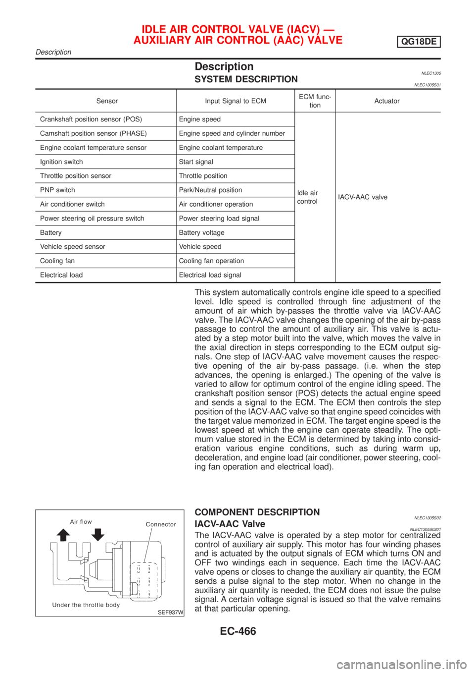
SEF937W
COMPONENT DESCRIPTIONNLEC1305S02IACV-AAC ValveNLEC1305S0201The IACV-AAC valve is operated by a step motor for centralized
control of auxiliary air supply. This motor has four winding phases
and is actuated by the output signals of ECM which turns ON and
OFF two windings each in sequence. Each time the IACV-AAC
valve opens or closes to change the auxiliary air quantity, the ECM
sends a pulse signal to the step motor. When no change in the
auxiliary air quantity is needed, the ECM does not issue the pulse
signal. A certain voltage signal is issued so that the valve remains
at that particular opening.
IDLE AIR CONTROL VALVE (IACV) Ð
AUXILIARY AIR CONTROL (AAC) VALVE
QG18DE
Description
EC-466
Page 1076 of 3051
SYMPTOM
Reference
page
HARD/NO START/RESTART (EXCP. HA)
ENGINE STALL
HESITATION/SURGING/FLAT SPOT
SPARK KNOCK/DETONATION
LACK OF POWER/POOR ACCELERATION
HIGH IDLE/LOW IDLE
ROUGH IDLE/HUNTING
IDLING VIBRATION
SLOW/NO RETURN TO IDLE
OVERHEATS/WATER TEMPERATURE HIGH
EXCESSIVE FUEL CONSUMPTION
EXCESSIVE OIL CONSUMPTION
BATTERY DEAD (UNDER CHARGE)
Warranty symptom code AA AB AC AD AE AF AG AH AJ AK AL AM HA
Engine Cylinder head
55555 55 5
EM section Cylinder head gasket 4 3
Cylinder block
66666 66 64 Piston
Piston ring
Connecting rod
Bearing
Crankshaft
Valve
mecha-
nismTiming chain
55555 55 5 EMsection Camshaft
Intake valve
3
Exhaust valve
Exhaust Exhaust manifold/Tube/Muffler/
Gasket
55555 55 5 FEsection
Three way catalyst
Lubrica-
tionOil pan/Oil strainer/Oil pump/Oil
filter/Oil gallery
55555 55 5MA, EM and
LC sections
Oil level (Low)/Filthy oil
LC section Cooling Radiator/Hose/Radiator filler cap
55555 55 45 Thermostat 5
Water pump
Water gallery
Cooling fan 5 EC-882
Coolant level (low)/Contaminated
coolantMA section
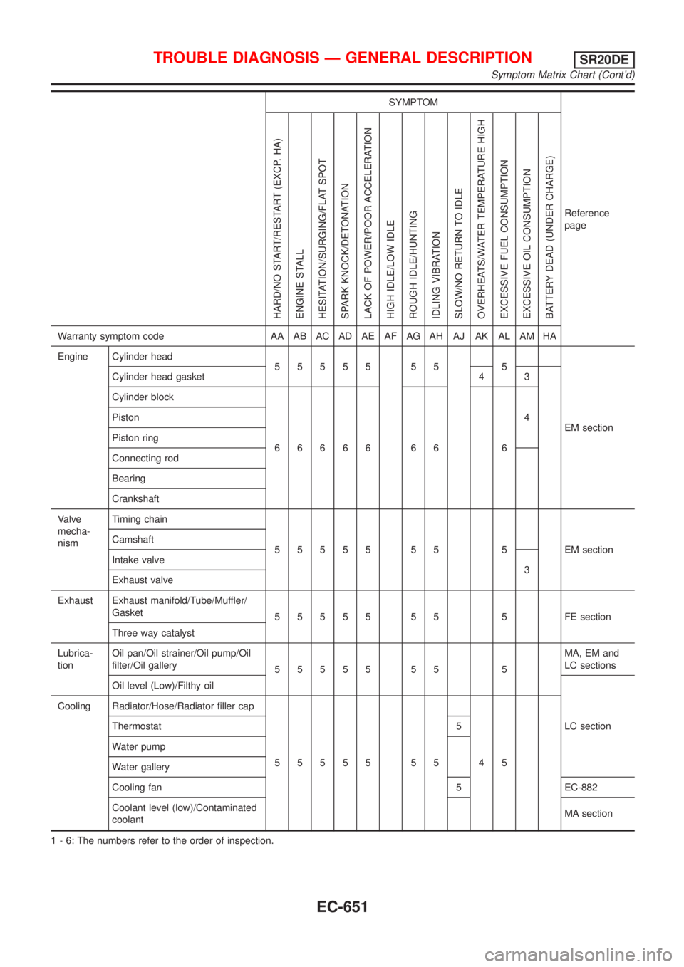
1 - 6: The numbers refer to the order of inspection.
TROUBLE DIAGNOSIS Ð GENERAL DESCRIPTIONSR20DE
Symptom Matrix Chart (Cont'd)
EC-651
Page 1288 of 3051
DescriptionNLEC1768SYSTEM DESCRIPTIONNLEC1768S01
Sensor Input Signal to ECMECM func-
tionActuator
Camshaft position sensor Engine speed
Idle air
controlIACV-AAC valve Mass air flow sensor Amount of intake air
Engine coolant temperature sensor Engine coolant temperature
Ignition switch Start signal
Throttle position sensor Throttle position
Park/neutral position (PNP) switch Park/neutral position
Air conditioner switch Air conditioner operation
Power steering oil pressure switch Power steering load signal
Battery Battery voltage
Vehicle speed sensor Vehicle speed
Intake air temperature sensor Intake air temperature
Cooling fan Cooling fan operation
Electrical load Electrical load signal
This system automatically controls engine idle speed to a specified
level. Idle speed is controlled through fine adjustment of the
amount of air which by-passes the throttle valve via IACV-AAC
valve. The IACV-AAC valve changes the opening of the air by-pass
passage to control the amount of auxiliary air. This valve is actu-
ated by a step motor built into the valve, which moves the valve in
the axial direction in steps corresponding to the ECM output sig-
nals. One step of IACV-AAC valve movement causes the respec-
tive opening of the air by-pass passage. (i.e. when the step
advances, the opening is enlarged.) The opening of the valve is
varied to allow for optimum control of the engine idling speed. The
camshaft position sensor detects the actual engine speed and
sends a signal to the ECM. The ECM then controls the step posi-
tion of the IACV-AAC valve so that engine speed coincides with the
target value memorized in ECM. The target engine speed is the
lowest speed at which the engine can operate steadily. The opti-
mum value stored in the ECM is determined by takig into consid-
eration various engine conditions, such as during warm up,
deceleration, and engine load (air conditioner, power steering and
cooling fan operation).
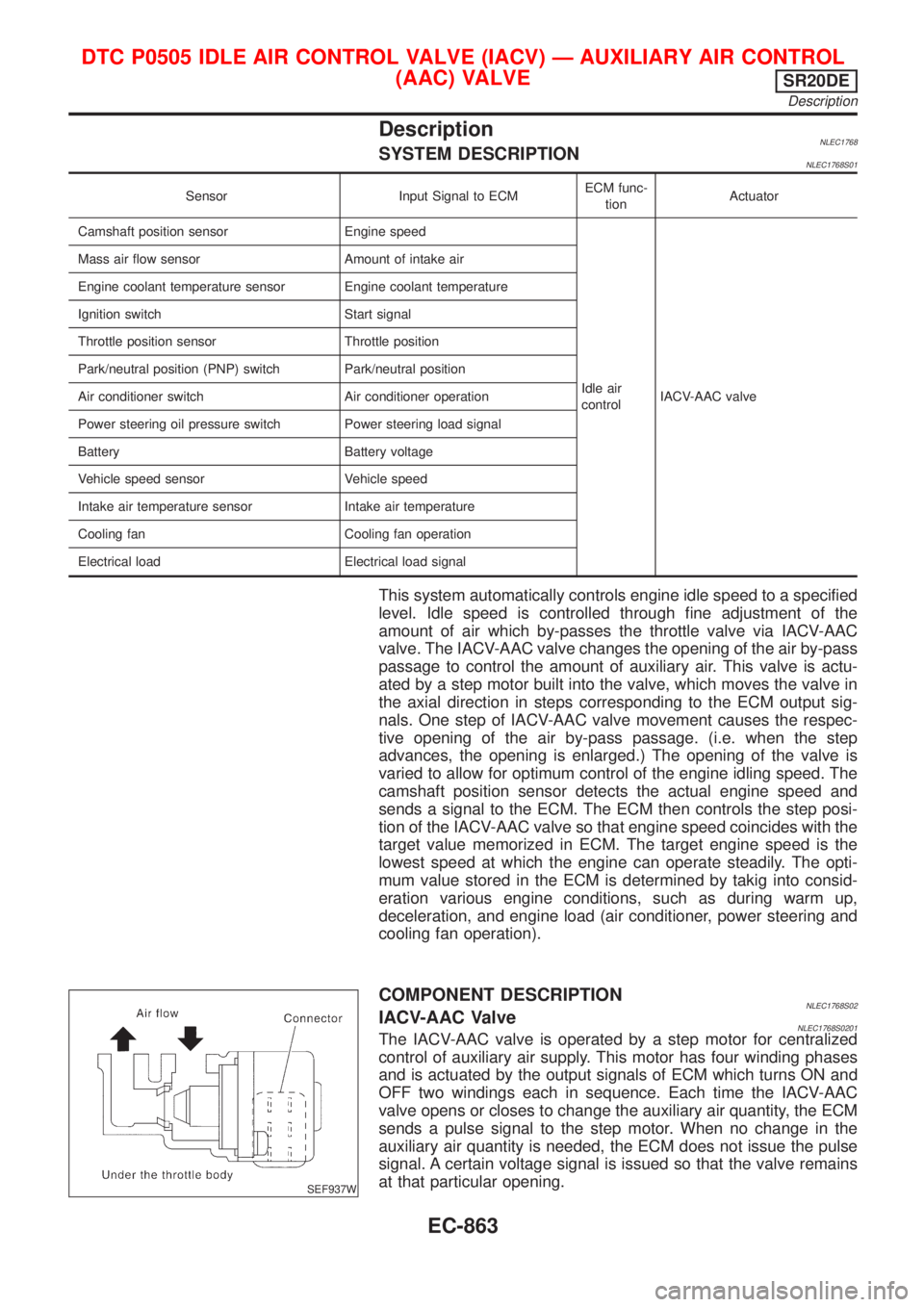
SEF937W
COMPONENT DESCRIPTIONNLEC1768S02IACV-AAC ValveNLEC1768S0201The IACV-AAC valve is operated by a step motor for centralized
control of auxiliary air supply. This motor has four winding phases
and is actuated by the output signals of ECM which turns ON and
OFF two windings each in sequence. Each time the IACV-AAC
valve opens or closes to change the auxiliary air quantity, the ECM
sends a pulse signal to the step motor. When no change in the
auxiliary air quantity is needed, the ECM does not issue the pulse
signal. A certain voltage signal is issued so that the valve remains
at that particular opening.
DTC P0505 IDLE AIR CONTROL VALVE (IACV) Ð AUXILIARY AIR CONTROL
(AAC) VALVE
SR20DE
Description
EC-863
Page 1308 of 3051
MONITOR ITEM CONDITION SPECIFICATION
COOLING FAN+After warming up engine, idle
the engine.
+Air conditioner switch: OFFEngine coolant temperature is less
than 95ÉC (203ÉF)OFF
Engine coolant temperature is
95ÉC (203ÉF) and 105ÉC (221ÉF)LOW
Engine coolant temperature is
105ÉC (221ÉF) or moreHIGH
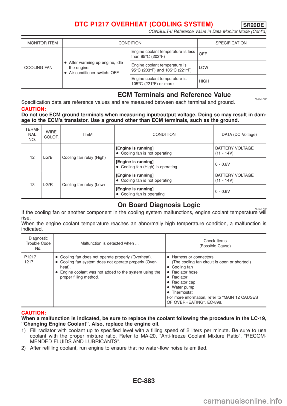
ECM Terminals and Reference ValueNLEC1769Specification data are reference values and are measured between each terminal and ground.
CAUTION:
Do not use ECM ground terminals when measuring input/output voltage. Doing so may result in dam-
age to the ECM's transistor. Use a ground other than ECM terminals, such as the ground.
TERMI-
NAL
NO.WIRE
COLORITEM CONDITION DATA (DC Voltage)
12 LG/B Cooling fan relay (High)[Engine is running]
+Cooling fan is not operatingBATTERY VOLTAGE
(11 - 14V)
[Engine is running]
+Cooling fan (High) is operating0 - 0.6V
13 LG/R Cooling fan relay (Low)[Engine is running]
+Cooling fan is not operatingBATTERY VOLTAGE
(11 - 14V)
[Engine is running]
+Cooling fan is operating0 - 0.6V
On Board Diagnosis LogicNLEC1770If the cooling fan or another component in the cooling system malfunctions, engine coolant temperature will
rise.
When the engine coolant temperature reaches an abnormally high temperature condition, a malfunction is
indicated.
Diagnostic
Trouble Code
No.Malfunction is detected when ...Check Items
(Possible Cause)
P1217
1217+Cooling fan does not operate properly (Overheat).
+Cooling fan system does not operate properly (Over-
heat).
+Engine coolant was not added to the system using the
proper filling method.+Harness or connectors
(The cooling fan circuit is open or shorted.)
+Cooling fan
+Radiator hose
+Radiator
+Radiator cap
+Water pump
+Thermostat
For more information, refer to ªMAIN 12 CAUSES
OF OVERHEATINGº, EC-898.
CAUTION:
When a malfunction is indicated, be sure to replace the coolant following the procedure in the LC-19,
ªChanging Engine Coolantº. Also, replace the engine oil.
1) Fill radiator with coolant up to specified level with a filling speed of 2 liters per minute. Be sure to use
coolant with the proper mixture ratio. Refer to MA-20, ªAnti-freeze Coolant Mixture Ratioº, ªRECOM-
MENDED FLUIDS AND LUBRICANTSº.
2) After refilling coolant, run engine to ensure that no water-flow noise is emitted.
DTC P1217 OVERHEAT (COOLING SYSTEM)SR20DE
CONSULT-II Reference Value in Data Monitor Mode (Cont'd)
EC-883
Page 1420 of 3051
DescriptionNLEC1836SYSTEM DESCRIPTIONNLEC1836S01
Sensor Input Signal to ECMECM func-
tionActuator
Camshaft position sensor Engine speed
Idle air
controlIACV-AAC valve Mass air flow sensor Amount of intake air
Engine coolant temperature sensor Engine coolant temperature
Ignition switch Start signal
Throttle position sensor Throttle position
Park/neutral position (PNP) switch Park/neutral position
Air conditioner switch Air conditioner operation
Power steering oil pressure switch Power steering load signal
Battery Battery voltage
Vehicle speed sensor Vehicle speed
Intake air temperature sensor Intake air temperature
Cooling fan Cooling fan operation
Electrical load Electrical load signal
This system automatically controls engine idle speed to a specified
level. Idle speed is controlled through fine adjustment of the
amount of air which by-passes the throttle valve via IACV-AAC
valve. The IACV-AAC valve changes the opening of the air by-pass
passage to control the amount of auxiliary air. This valve is actu-
ated by a step motor built into the valve, which moves the valve in
the axial direction in steps corresponding to the ECM output sig-
nals. One step of IACV-AAC valve movement causes the respec-
tive opening of the air by-pass passage. (i.e. when the step
advances, the opening is enlarged.) The opening of the valve is
varied to allow for optimum control of the engine idling speed. The
camshaft position sensor detects the actual engine speed and
sends a signal to the ECM. The ECM then controls the step posi-
tion of the IACV-AAC valve so that engine speed coincides with the
target value memorized in ECM. The target engine speed is the
lowest speed at which the engine can operate steadily. The opti-
mum value stored in the ECM is determined by takig into consid-
eration various engine conditions, such as during warm up,
deceleration, and engine load (air conditioner, power steering and
cooling fan operation).
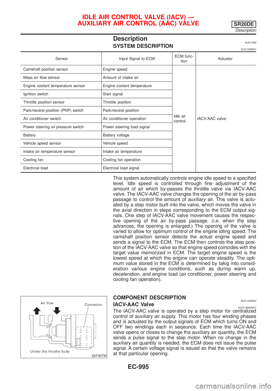
SEF937W
COMPONENT DESCRIPTIONNLEC1836S02IACV-AAC ValveNLEC1836S0201The IACV-AAC valve is operated by a step motor for centralized
control of auxiliary air supply. This motor has four winding phases
and is actuated by the output signals of ECM which turns ON and
OFF two windings each in seqeunce. Each time the IACV-AAC
valve opens or closes to change tha auxiliary air quantity, the ECM
sends a pulse signal to the step motor. When no change in the
auxiliary air quantity is needed, the ECM does not issue the pulse
signal. A certain voltage signal is issued so that the valve remains
at that particular opening.
IDLE AIR CONTROL VALVE (IACV) Ð
AUXILIARY AIR CONTROL (AAC) VALVE
SR20DE
Description
EC-995
Page 1627 of 3051
![NISSAN ALMERA TINO 2001 Service Repair Manual TERMI-
NAL
NO.WIRE
COLORITEM CONDITION DATA(DC Voltage)
221 LG/B Cooling fan relay (High)[Engine is running]
+Cooling fans are not operating
+Cooling fans are operating at low speedBATTERY VOLTAGE
(11](/manual-img/5/57352/w960_57352-1626.png "NISSAN ALMERA TINO 2001 Service Repair Manual TERMI-
NAL
NO.WIRE
COLORITEM CONDITION DATA(DC Voltage)
221 LG/B Cooling fan relay (High)[Engine is running]
+Cooling fans are not operating
+Cooling fans are operating at low speedBATTERY VOLTAGE
(11")
TERMI-
NAL
NO.WIRE
COLORITEM CONDITION DATA(DC Voltage)
221 LG/B Cooling fan relay (High)[Engine is running]
+Cooling fans are not operating
+Cooling fans are operating at low speedBATTERY VOLTAGE
(11 - 14V)
[Engine is running]
+Cooling fans are operating at high speedApproximately 0.1V
On Board Diagnosis LogicNLEC0663This diagnosis continuously monitors the engine coolant temperature.
If the cooling fan or another component in the cooling system malfunctions, engine coolant temperature will
rise.
When the engine coolant temperature reaches an abnormally high temperature condition, a malfunction is
indicated.
DTC Malfunction is detected when ... Check Items (Possible Cause)
P1217
0208+Cooling fan does not operate properly (Overheat).
+Cooling fan system does not operate properly
(Overheat).
+Engine coolant was not added to the system using
the proper filling method.+Harness or connectors
(The cooling fan circuit is open or shorted.)
+Cooling fan
+Radiator hose
+Radiator
+Radiator cap
+Water pump
+Thermostat
+Engine coolant temperature sensor
For more information, refer to ªMAIN 12 CAUSES OF
OVERHEATINGº, EC-1217.
CAUTION:
When a malfunction is indicated, be sure to replace the coolant following the procedure in the LC-59,
ªChanging Engine Coolantº. Also, replace the engine oil.
1) Fill radiator with coolant up to specified level with a filling speed of 2 liters per minute. Be sure
to use coolant with the proper mixture ratio. Refer to MA-22, ªEngine Coolant Mixture Ratioº.
2) After refilling coolant, run engine to ensure that no water-flow noise is emitted.
DTC P1217 OVER HEATYD22DDTI
ECM Terminals and Reference Value (Cont'd)
EC-1202
Page 1803 of 3051
Aiming AdjustmentNLEL0016For details, refer to the regulations in your own country.
Before performing aiming adjustment, check the following.
1) Keep all tires inflated to correct pressures.
2) Place vehicle on flat surface.
3) See that there is no-load in vehicle (coolant, engine oil filled up
to correct level and full fuel tank) other than the driver (or
equivalent weight placed in driver's position).
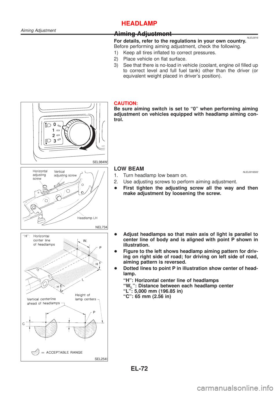
SEL984W
CAUTION:
Be sure aiming switch is set to ª0º when performing aiming
adjustment on vehicles equipped with headlamp aiming con-
trol.
NEL734
LOW BEAMNLEL0016S021. Turn headlamp low beam on.
2. Use adjusting screws to perform aiming adjustment.
+First tighten the adjusting screw all the way and then
make adjustment by loosening the screw.
SEL254I
+Adjust headlamps so that main axis of light is parallel to
center line of body and is aligned with point P shown in
illustration.
+Figure to the left shows headlamp aiming pattern for driv-
ing on right side of road; for driving on left side of road,
aiming pattern is reversed.
+Dotted lines to point P in illustration show center of head-
lamp.
ªHº: Horizontal center line of headlamps
ªW
Lº: Distance between each headlamp center
ªLº: 5,000 mm (196.85 in)
ªCº: 65 mm (2.56 in)
HEADLAMP
Aiming Adjustment
EL-72
Page 1829 of 3051
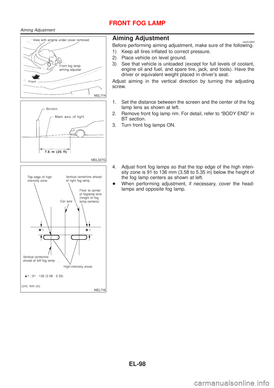
NEL714
Aiming Adjustment=NLEL0029Before performing aiming adjustment, make sure of the following.
1) Keep all tires inflated to correct pressure.
2) Place vehicle on level ground.
3) See that vehicle is unloaded (except for full levels of coolant,
engine oil and fuel, and spare tire, jack, and tools). Have the
driver or equivalent weight placed in driver's seat.
Adjust aiming in the vertical direction by turning the adjusting
screw.
MEL327G
1. Set the distance between the screen and the center of the fog
lamp lens as shown at left.
2. Remove front fog lamp rim. For detail, refer to ªBODY ENDº in
BT section.
3. Turn front fog lamps ON.
NEL716
4. Adjust front fog lamps so that the top edge of the high inten-
sity zone is 91 to 136 mm (3.58 to 5.35 in) below the height of
the fog lamp centers as shown at left.
+When performing adjustment, if necessary, cover the head-
lamps and opposite fog lamp.
FRONT FOG LAMP
Aiming Adjustment
EL-98