2001 NISSAN ALMERA TINO OBD port
[x] Cancel search: OBD portPage 426 of 3051
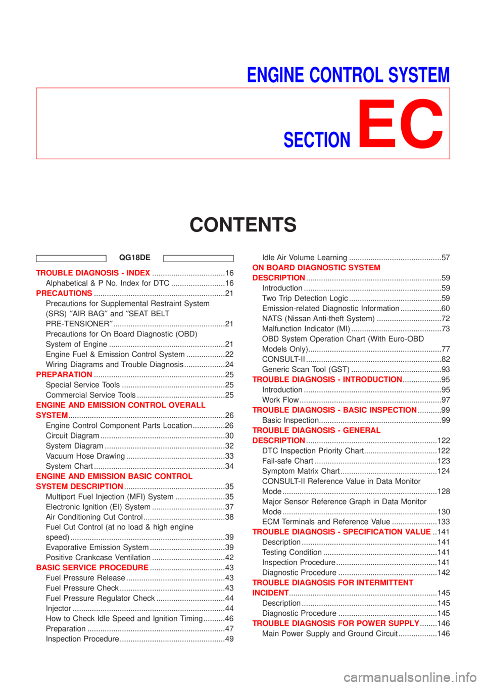
ENGINE CONTROL SYSTEM
SECTION
EC
CONTENTS
QG18DE
TROUBLE DIAGNOSIS - INDEX..................................16
Alphabetical & P No. Index for DTC .........................16
PRECAUTIONS.............................................................21
Precautions for Supplemental Restraint System
(SRS)²AIR BAG²and²SEAT BELT
PRE-TENSIONER²....................................................21
Precautions for On Board Diagnostic (OBD)
System of Engine ......................................................21
Engine Fuel & Emission Control System ..................22
Wiring Diagrams and Trouble Diagnosis ...................24
PREPARATION.............................................................25
Special Service Tools ................................................25
Commercial Service Tools .........................................25
ENGINE AND EMISSION CONTROL OVERALL
SYSTEM.........................................................................26
Engine Control Component Parts Location ...............26
Circuit Diagram ..........................................................30
System Diagram ........................................................32
Vacuum Hose Drawing ..............................................33
System Chart .............................................................34
ENGINE AND EMISSION BASIC CONTROL
SYSTEM DESCRIPTION...............................................35
Multiport Fuel Injection (MFI) System .......................35
Electronic Ignition (EI) System ..................................37
Air Conditioning Cut Control ......................................38
Fuel Cut Control (at no load & high engine
speed) ........................................................................39
Evaporative Emission System ...................................39
Positive Crankcase Ventilation ..................................42
BASIC SERVICE PROCEDURE...................................43
Fuel Pressure Release ..............................................43
Fuel Pressure Check .................................................43
Fuel Pressure Regulator Check ................................44
Injector .......................................................................44
How to Check Idle Speed and Ignition Timing ..........46
Preparation ................................................................47
Inspection Procedure .................................................49Idle Air Volume Learning ...........................................57
ON BOARD DIAGNOSTIC SYSTEM
DESCRIPTION...............................................................59
Introduction ................................................................59
Two Trip Detection Logic ...........................................59
Emission-related Diagnostic Information ...................60
NATS (Nissan Anti-theft System) ..............................72
Malfunction Indicator (MI) ..........................................73
OBD System Operation Chart (With Euro-OBD
Models Only)..............................................................77
CONSULT-II ...............................................................82
Generic Scan Tool (GST) ..........................................93
TROUBLE DIAGNOSIS - INTRODUCTION..................95
Introduction ................................................................95
Work Flow ..................................................................97
TROUBLE DIAGNOSIS - BASIC INSPECTION...........99
Basic Inspection.........................................................99
TROUBLE DIAGNOSIS - GENERAL
DESCRIPTION.............................................................122
DTC Inspection Priority Chart..................................122
Fail-safe Chart .........................................................123
Symptom Matrix Chart .............................................124
CONSULT-II Reference Value in Data Monitor
Mode ........................................................................128
Major Sensor Reference Graph in Data Monitor
Mode ........................................................................130
ECM Terminals and Reference Value .....................133
TROUBLE DIAGNOSIS - SPECIFICATION VALUE..141
Description ...............................................................141
Testing Condition .....................................................141
Inspection Procedure ...............................................141
Diagnostic Procedure ..............................................142
TROUBLE DIAGNOSIS FOR INTERMITTENT
INCIDENT.....................................................................145
Description ...............................................................145
Diagnostic Procedure ..............................................145
TROUBLE DIAGNOSIS FOR POWER SUPPLY........146
Main Power Supply and Ground Circuit ..................146
Page 432 of 3051
Crankshaft Position Sensor (POS) ..........................549
Camshaft Position Sensor (PHASE) .......................549
SR20DE
TROUBLE DIAGNOSIS - INDEX................................550
Alphabetical & P No. Index for DTC .......................550
PRECAUTIONS...........................................................555
Precautions for Supplemental Restraint System
(SRS)²AIR BAG²and²SEAT BELT
PRE-TENSIONER²..................................................555
Precautions for On Board Diagnostic (OBD)
System of Engine and CVT .....................................555
Engine Fuel & Emission Control System ................556
Wiring Diagrams and Trouble Diagnosis .................558
PREPARATION...........................................................559
Special Service Tools ..............................................559
Commercial Service Tools .......................................559
ENGINE AND EMISSION CONTROL OVERALL
SYSTEM.......................................................................560
Engine Control Component Parts Location .............560
Circuit Diagram ........................................................564
System Diagram ......................................................566
Vacuum Hose Drawing ............................................567
System Chart ...........................................................568
ENGINE AND EMISSION BASIC CONTROL
SYSTEM DESCRIPTION.............................................569
Multiport Fuel Injection (MFI) System .....................569
Electronic Ignition (EI) System ................................571
Air Conditioning Cut Control ....................................572
Fuel Cut Control (at no load & high engine
speed) ......................................................................573
Evaporative Emission System .................................573
Positive Crankcase Ventilation ................................576
BASIC SERVICE PROCEDURE.................................577
Fuel Pressure Release ............................................577
Fuel Pressure Check ...............................................577
Fuel Pressure Regulator Check ..............................578
Injector .....................................................................578
Idle Air Volume Learning .........................................581
ON BOARD DIAGNOSTIC SYSTEM
DESCRIPTION.............................................................583
Introduction ..............................................................583
Two Trip Detection Logic .........................................583
Emission-related Diagnostic Information .................584
NATS (Nissan Anti-theft System) ............................597
Malfunction Indicator (MI) ........................................598
OBD System Operation Chart (With Euro-OBD
Models Only)............................................................602
CONSULT-II .............................................................607
Generic Scan Tool (GST) ........................................617
TROUBLE DIAGNOSIS - INTRODUCTION................619
Introduction ..............................................................619Work Flow ................................................................621
TROUBLE DIAGNOSIS - BASIC INSPECTION.........623
Basic Inspection (Models with Throttle Opener) .....623
Basic Inspection (Models without Throttle
Opener) ....................................................................638
TROUBLE DIAGNOSIS - GENERAL
DESCRIPTION.............................................................646
DTC Inspection Priority Chart..................................646
Fail-safe Chart .........................................................647
Symptom Matrix Chart .............................................648
CONSULT-II Reference Value in Data Monitor
Mode ........................................................................652
Major Sensor Reference Graph in Data Monitor
Mode ........................................................................654
ECM Terminals and Reference Value .....................657
TROUBLE DIAGNOSIS - SPECIFICATION VALUE..666
Description ...............................................................666
Testing Condition .....................................................666
Inspection Procedure ...............................................666
Diagnostic Procedure ..............................................667
TROUBLE DIAGNOSIS FOR INTERMITTENT
INCIDENT.....................................................................670
Description ...............................................................670
Diagnostic Procedure ..............................................670
TROUBLE DIAGNOSIS FOR POWER SUPPLY........671
Main Power Supply and Ground Circuit ..................671
DTC P0100 MASS AIR FLOW SENSOR (MAFS)......679
Component Description ...........................................679
CONSULT-II Reference Value in Data Monitor
Mode ........................................................................679
ECM Terminals and Reference Value .....................679
On Board Diagnosis Logic.......................................679
Fail-safe Mode .........................................................680
DTC Confirmation Procedure ..................................680
Wiring Diagram ........................................................682
Diagnostic Procedure ..............................................684
Component Inspection .............................................686
DTC P0110 INTAKE AIR TEMPERATURE
SENSOR......................................................................687
Component Description ...........................................687
On Board Diagnosis Logic.......................................688
DTC Confirmation Procedure ..................................688
Wiring Diagram ........................................................689
Diagnostic Procedure ..............................................691
Component Inspection .............................................693
DTC P0115 ENGINE COOLANT TEMPERATURE
SENSOR (ECTS) (CIRCUIT).......................................694
Component Description ...........................................694
CONSULT-II Reference Value in Data Monitor
Mode ........................................................................694
On Board Diagnosis Logic.......................................694
Fail-safe Mode .........................................................695
CONTENTS(Cont'd)
EC-7
Page 509 of 3051
ItemDIAGNOSTIC TEST MODE
WORK
SUP-
PORTSELF-DIAGNOS-
TIC RESULTS
D ATA
MONI-
TORD ATA
MONI-
TOR
(SPEC)ACTIVE
TESTDTC & SRT
CONFIRMATION
DTC*1FREEZE
FRAME
DATA*2SRT
STA-
TUSDTC
WORK
SUP-
PORT
ENGINE CONTROL COMPONENT PARTS
OUT-
PUTInjectors X X X
Power transistor (Ignition
timing)X*3
(misfire)XXX
IACV-AAC valve X X*3 X X X
Intake valve timing control
solenoid valveXXX
EVAP canister purge volume
control solenoid valveX*3 X X X
Air conditioner relay X X
Fuel pump relay X X X X
EGR volume control valve
(where fitted)X*3 X X X X*3
Heated oxygen sensor 1
heater (front)X*3 X X X*3
Heated oxygen sensor 2
heater (rear)X*3 X X X*3
Cooling fan X X X
Swirl control valve control
solenoid valve (where fitted)X*3 X X X
Calculated load value X X X
X: Applicable
*1: This item includes 1st trip DTCs.
*2: This mode includes 1st trip freeze frame data or freeze frame data. The items appear on CONSULT-II screen in freeze frame data
mode only if a 1st trip DTC or DTC is detected. For details, refer to EC-61, EC-71.
*3: Not applicable for models without Euro-OBD system
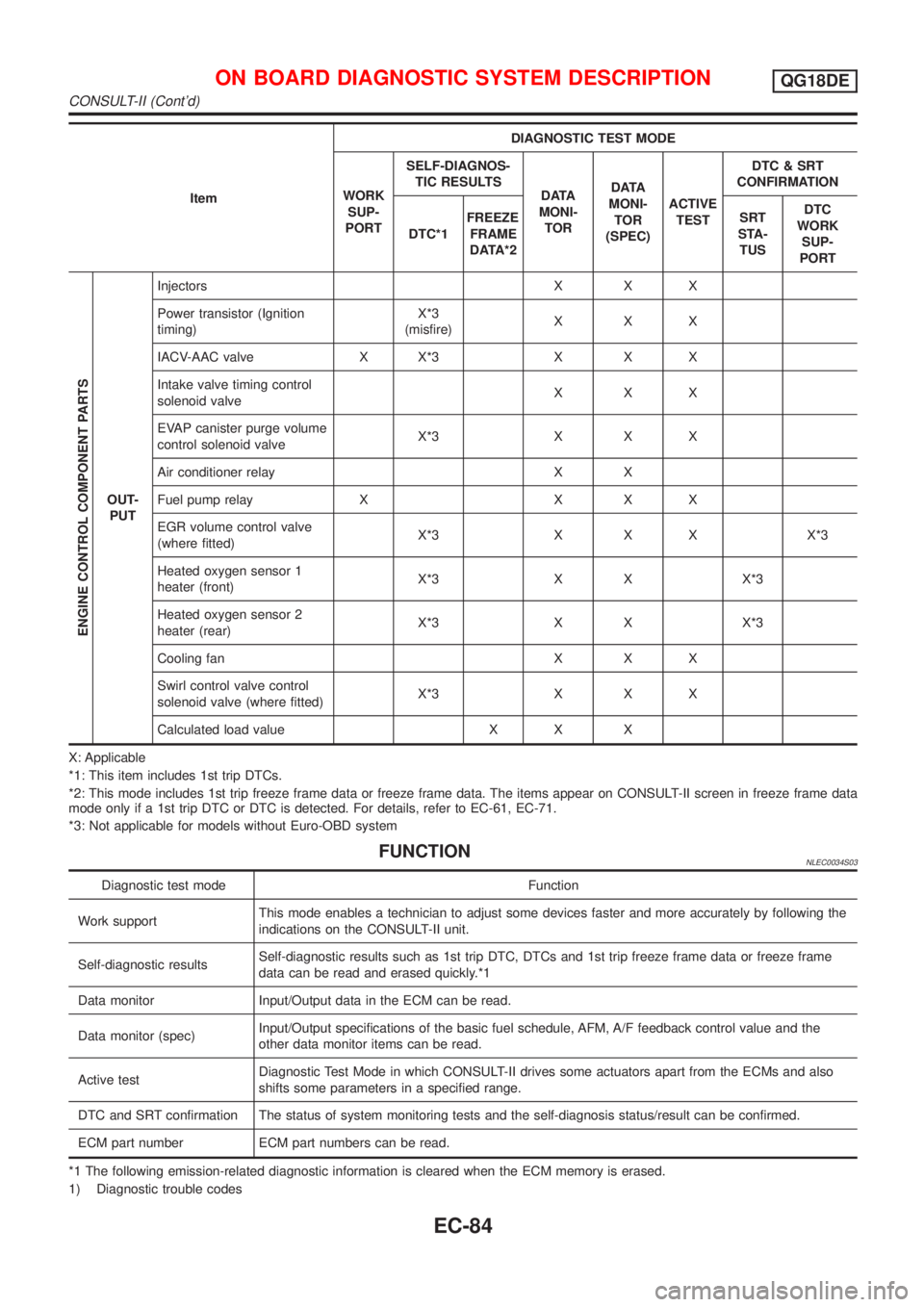
FUNCTIONNLEC0034S03
Diagnostic test mode Function
Work supportThis mode enables a technician to adjust some devices faster and more accurately by following the
indications on the CONSULT-II unit.
Self-diagnostic resultsSelf-diagnostic results such as 1st trip DTC, DTCs and 1st trip freeze frame data or freeze frame
data can be read and erased quickly.*1
Data monitor Input/Output data in the ECM can be read.
Data monitor (spec)Input/Output specifications of the basic fuel schedule, AFM, A/F feedback control value and the
other data monitor items can be read.
Active testDiagnostic Test Mode in which CONSULT-II drives some actuators apart from the ECMs and also
shifts some parameters in a specified range.
DTC and SRT confirmation The status of system monitoring tests and the self-diagnosis status/result can be confirmed.
ECM part number ECM part numbers can be read.
*1 The following emission-related diagnostic information is cleared when the ECM memory is erased.
1) Diagnostic trouble codes
ON BOARD DIAGNOSTIC SYSTEM DESCRIPTIONQG18DE
CONSULT-II (Cont'd)
EC-84
Page 515 of 3051
TEST ITEM CONDITION JUDGEMENT CHECK ITEM (REMEDY)
IACV-AAC/V
OPENING+Engine: After warming up, idle
the engine.
+Change the IACV-AAC valve
opening steps using CONSULT-
II.Engine speed changes according
to the opening steps.+Harness and connector
+IACV-AAC valve
POWER BAL-
ANCE+Engine: After warming up, idle
the engine.
+Air conditioner switch ªOFFº
+Shift lever ªNº
+Cut off each injector signal one
at a time using CONSULT-II.Engine runs rough or dies.+Harness and connector
+Compression
+Injectors
+Power transistor
+Spark plugs
+Ignition coils
COOLING FAN+Ignition switch: ON
+Turn the cooling fan ªONº and
ªOFFº using CONSULT-II.Cooling fan moves and stops.+Harness and connector
+Cooling fan motor
ENG COOLANT
TEMP+Engine: Return to the original
trouble condition
+Change the engine coolant tem-
perature indication using CON-
SULT-II.If trouble symptom disappears, see
CHECK ITEM.+Harness and connector
+Engine coolant temperature sen-
sor
+Fuel injectors
FUEL PUMP
RELAY+Ignition switch: ON
(Engine stopped)
+Turn the fuel pump relay ªONº
and ªOFFº using CONSULT-II
and listen to operating sound.Fuel pump relay makes the operat-
ing sound.+Harness and connector
+Fuel pump relay
EGR VOL
CONT/V
(where fitted)+Engine: After warming up, idle
the engine.
+Change the EGR volume control
valve opening step using CON-
SULT-II.Engine speed changes according
to the opening step.+Harness and connector
+EGR volume control valve
VALVE TIMING
SOL+Ignition switch: ON
+Turn intake valve timing control
solenoid valve ªONº and ªOFFº
using CONSULT-II and listen for
operating sound.Intake valve timing control solenoid
valve makes an operating sound.+Harness and connector
+Intake valve timing control sole-
noid valve
SWIRL CONT
S O L VA LV E
(where fitted)+Ignition switch: ON
+Turn solenoid valve ªONº and
ªOFFº with CONSULT-II and lis-
ten for operating sound.Solenoid valve makes an operating
sound.+Harness and connector
+Solenoid valve
PURG VOL
CONT/V+Engine: After warming up, idle
the engine.
+Change the EVAP canister purge
volume control solenoid valve
opening percent using CON-
SULT-II.Engine speed changes according
to the opening percent.+Harness and connector
+EVAP canister purge volume
control solenoid valve
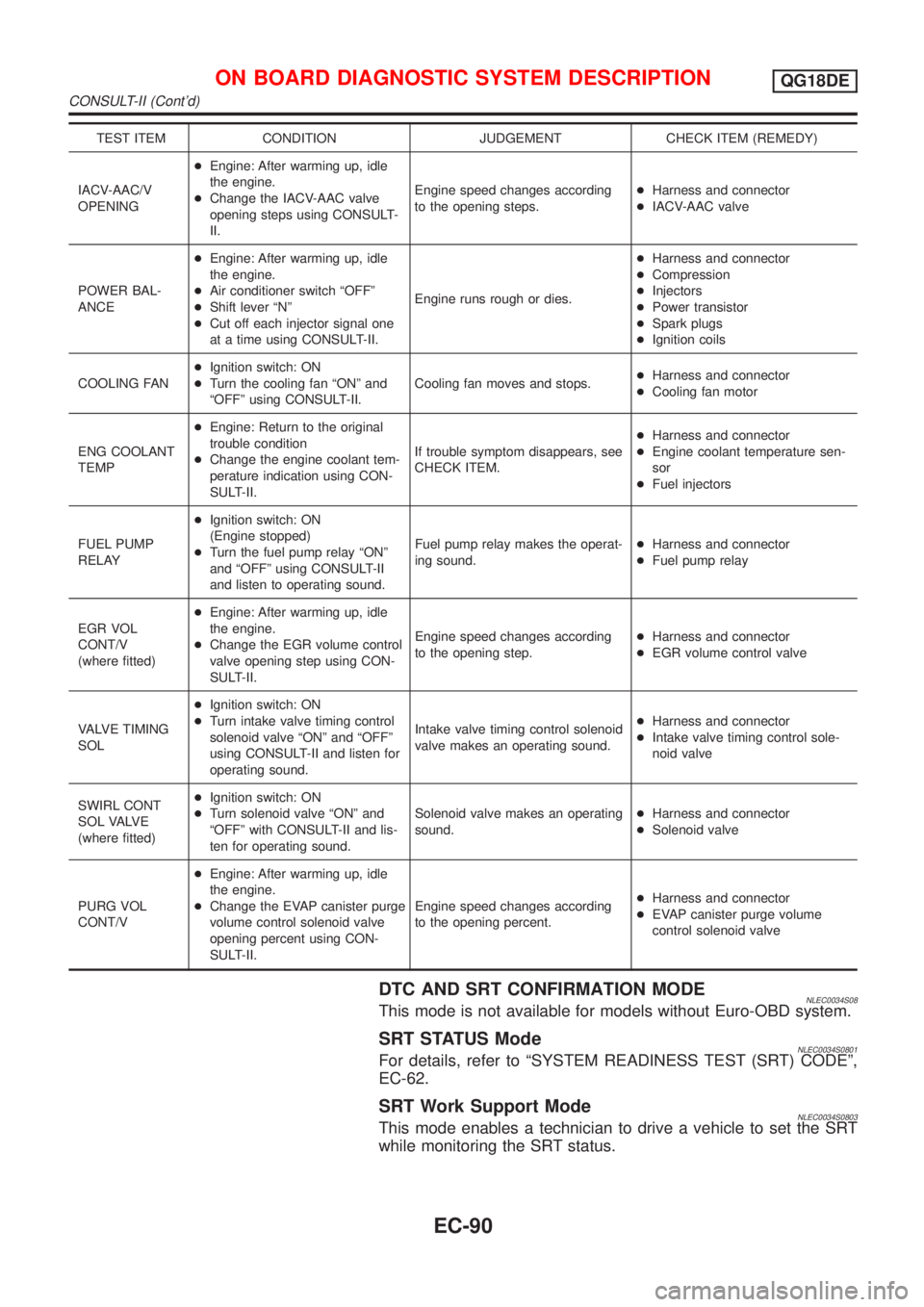
DTC AND SRT CONFIRMATION MODENLEC0034S08This mode is not available for models without Euro-OBD system.
SRT STATUS ModeNLEC0034S0801For details, refer to ªSYSTEM READINESS TEST (SRT) CODEº,
EC-62.
SRT Work Support ModeNLEC0034S0803This mode enables a technician to drive a vehicle to set the SRT
while monitoring the SRT status.
ON BOARD DIAGNOSTIC SYSTEM DESCRIPTIONQG18DE
CONSULT-II (Cont'd)
EC-90
Page 1033 of 3051
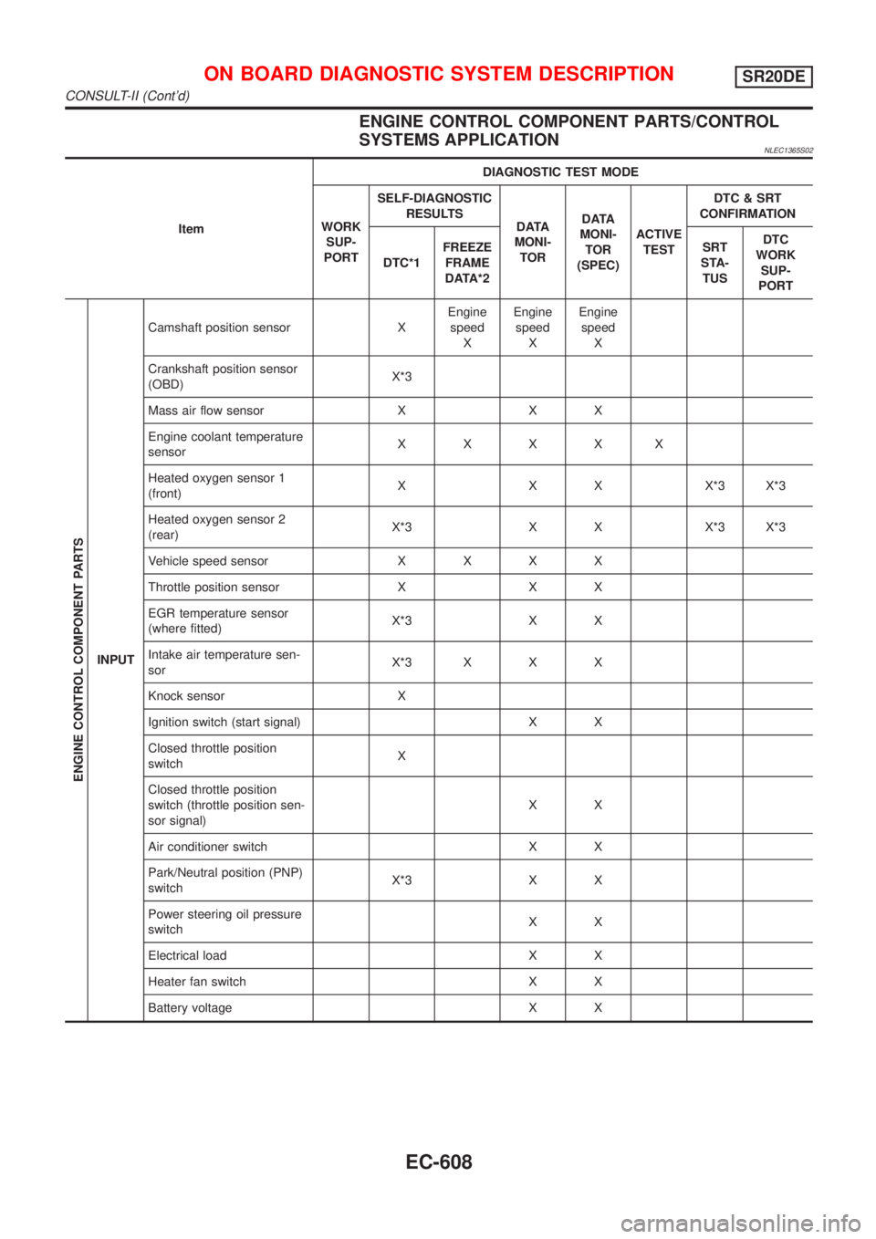
ENGINE CONTROL COMPONENT PARTS/CONTROL
SYSTEMS APPLICATION
NLEC1365S02
ItemDIAGNOSTIC TEST MODE
WORK
SUP-
PORTSELF-DIAGNOSTIC
RESULTS
D ATA
MONI-
TORD ATA
MONI-
TOR
(SPEC)ACTIVE
TESTDTC & SRT
CONFIRMATION
DTC*1FREEZE
FRAME
DATA*2SRT
STA-
TUSDTC
WORK
SUP-
PORT
ENGINE CONTROL COMPONENT PARTS
INPUTCamshaft position sensor XEngine
speed
XEngine
speed
XEngine
speed
X
Crankshaft position sensor
(OBD)X*3
Mass air flow sensor X X X
Engine coolant temperature
sensorXXXXX
Heated oxygen sensor 1
(front)X X X X*3 X*3
Heated oxygen sensor 2
(rear)X*3 X X X*3 X*3
Vehicle speed sensorXXXX
Throttle position sensor X X X
EGR temperature sensor
(where fitted)X*3 X X
Intake air temperature sen-
sorX*3 X X X
Knock sensor X
Ignition switch (start signal) X X
Closed throttle position
switchX
Closed throttle position
switch (throttle position sen-
sor signal)XX
Air conditioner switch X X
Park/Neutral position (PNP)
switchX*3 X X
Power steering oil pressure
switchXX
Electrical load X X
Heater fan switch X X
Battery voltage X X
ON BOARD DIAGNOSTIC SYSTEM DESCRIPTIONSR20DE
CONSULT-II (Cont'd)
EC-608
Page 1034 of 3051
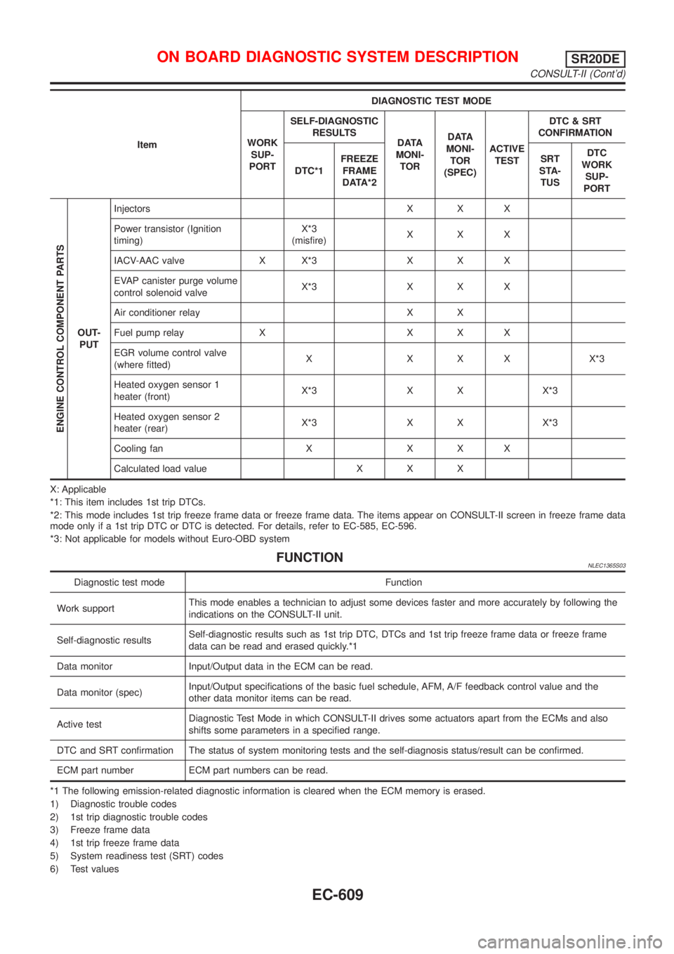
ItemDIAGNOSTIC TEST MODE
WORK
SUP-
PORTSELF-DIAGNOSTIC
RESULTS
D ATA
MONI-
TORD ATA
MONI-
TOR
(SPEC)ACTIVE
TESTDTC & SRT
CONFIRMATION
DTC*1FREEZE
FRAME
DATA*2SRT
STA-
TUSDTC
WORK
SUP-
PORT
ENGINE CONTROL COMPONENT PARTS
OUT-
PUTInjectors X X X
Power transistor (Ignition
timing)X*3
(misfire)XXX
IACV-AAC valve X X*3 X X X
EVAP canister purge volume
control solenoid valveX*3 X X X
Air conditioner relay X X
Fuel pump relay X X X X
EGR volume control valve
(where fitted)X X X X X*3
Heated oxygen sensor 1
heater (front)X*3 X X X*3
Heated oxygen sensor 2
heater (rear)X*3 X X X*3
Cooling fan X X X X
Calculated load value X X X
X: Applicable
*1: This item includes 1st trip DTCs.
*2: This mode includes 1st trip freeze frame data or freeze frame data. The items appear on CONSULT-II screen in freeze frame data
mode only if a 1st trip DTC or DTC is detected. For details, refer to EC-585, EC-596.
*3: Not applicable for models without Euro-OBD system
FUNCTIONNLEC1365S03
Diagnostic test mode Function
Work supportThis mode enables a technician to adjust some devices faster and more accurately by following the
indications on the CONSULT-II unit.
Self-diagnostic resultsSelf-diagnostic results such as 1st trip DTC, DTCs and 1st trip freeze frame data or freeze frame
data can be read and erased quickly.*1
Data monitor Input/Output data in the ECM can be read.
Data monitor (spec)Input/Output specifications of the basic fuel schedule, AFM, A/F feedback control value and the
other data monitor items can be read.
Active testDiagnostic Test Mode in which CONSULT-II drives some actuators apart from the ECMs and also
shifts some parameters in a specified range.
DTC and SRT confirmation The status of system monitoring tests and the self-diagnosis status/result can be confirmed.
ECM part number ECM part numbers can be read.
*1 The following emission-related diagnostic information is cleared when the ECM memory is erased.
1) Diagnostic trouble codes
2) 1st trip diagnostic trouble codes
3) Freeze frame data
4) 1st trip freeze frame data
5) System readiness test (SRT) codes
6) Test values
ON BOARD DIAGNOSTIC SYSTEM DESCRIPTIONSR20DE
CONSULT-II (Cont'd)
EC-609
Page 1040 of 3051
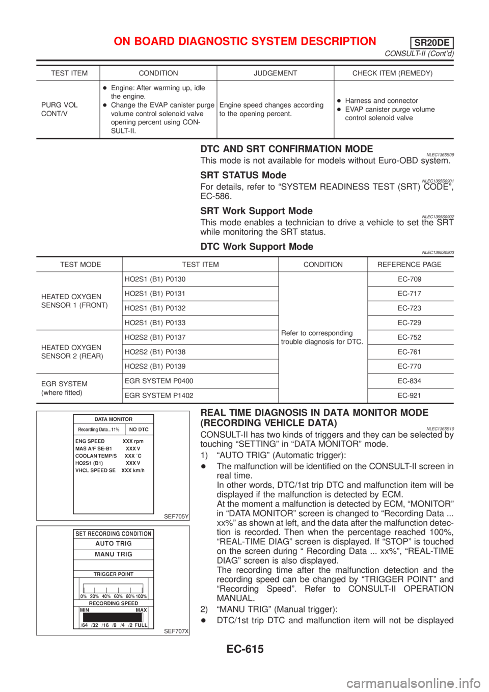
TEST ITEM CONDITION JUDGEMENT CHECK ITEM (REMEDY)
PURG VOL
CONT/V+Engine: After warming up, idle
the engine.
+Change the EVAP canister purge
volume control solenoid valve
opening percent using CON-
SULT-II.Engine speed changes according
to the opening percent.+Harness and connector
+EVAP canister purge volume
control solenoid valve
DTC AND SRT CONFIRMATION MODENLEC1365S09This mode is not available for models without Euro-OBD system.
SRT STATUS ModeNLEC1365S0901For details, refer to ªSYSTEM READINESS TEST (SRT) CODEº,
EC-586.
SRT Work Support ModeNLEC1365S0902This mode enables a technician to drive a vehicle to set the SRT
while monitoring the SRT status.
DTC Work Support ModeNLEC1365S0903
TEST MODE TEST ITEM CONDITION REFERENCE PAGE
HEATED OXYGEN
SENSOR 1 (FRONT)HO2S1 (B1) P0130
Refer to corresponding
trouble diagnosis for DTC.EC-709
HO2S1 (B1) P0131 EC-717
HO2S1 (B1) P0132 EC-723
HO2S1 (B1) P0133 EC-729
HEATED OXYGEN
SENSOR 2 (REAR)HO2S2 (B1) P0137 EC-752
HO2S2 (B1) P0138 EC-761
HO2S2 (B1) P0139 EC-770
EGR SYSTEM
(where fitted)EGR SYSTEM P0400 EC-834
EGR SYSTEM P1402 EC-921
SEF705Y
SEF707X
REAL TIME DIAGNOSIS IN DATA MONITOR MODE
(RECORDING VEHICLE DATA)
NLEC1365S10CONSULT-II has two kinds of triggers and they can be selected by
touching ªSETTINGº in ªDATA MONITORº mode.
1) ªAUTO TRIGº (Automatic trigger):
+The malfunction will be identified on the CONSULT-II screen in
real time.
In other words, DTC/1st trip DTC and malfunction item will be
displayed if the malfunction is detected by ECM.
At the moment a malfunction is detected by ECM, ªMONITORº
in ªDATA MONITORº screen is changed to ªRecording Data ...
xx%º as shown at left, and the data after the malfunction detec-
tion is recorded. Then when the percentage reached 100%,
ªREAL-TIME DIAGº screen is displayed. If ªSTOPº is touched
on the screen during ª Recording Data ... xx%º, ªREAL-TIME
DIAGº screen is also displayed.
The recording time after the malfunction detection and the
recording speed can be changed by ªTRIGGER POINTº and
ªRecording Speedº. Refer to CONSULT-II OPERATION
MANUAL.
2) ªMANU TRIGº (Manual trigger):
+DTC/1st trip DTC and malfunction item will not be displayed
ON BOARD DIAGNOSTIC SYSTEM DESCRIPTIONSR20DE
CONSULT-II (Cont'd)
EC-615
Page 1737 of 3051
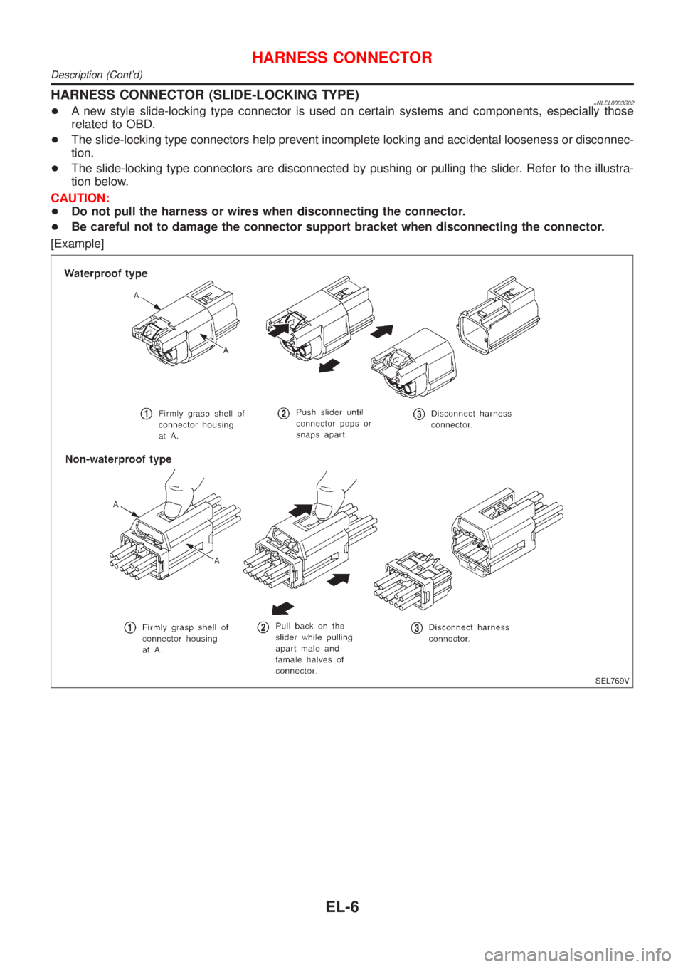
HARNESS CONNECTOR (SLIDE-LOCKING TYPE)=NLEL0003S02+A new style slide-locking type connector is used on certain systems and components, especially those
related to OBD.
+The slide-locking type connectors help prevent incomplete locking and accidental looseness or disconnec-
tion.
+The slide-locking type connectors are disconnected by pushing or pulling the slider. Refer to the illustra-
tion below.
CAUTION:
+Do not pull the harness or wires when disconnecting the connector.
+Be careful not to damage the connector support bracket when disconnecting the connector.
[Example]
SEL769V
HARNESS CONNECTOR
Description (Cont'd)
EL-6