2001 NISSAN ALMERA TINO display
[x] Cancel search: displayPage 1027 of 3051
MI Fuel mixture condition in the exhaust gas Air fuel ratio feedback control condition
*Remains ON or OFF Any condition Open loop system
*: Maintains conditions just before switching to open loop.
To check the heated oxygen sensor 1 (front) function, start engine in the Diagnostic Test Mode II and warm
it up until engine coolant temperature indicator points to the middle of the gauge.
Next run engine at about 2,000 rpm for about 2 minutes under no-load conditions. Then make sure that the
MI comes ON more than 5 times within 10 seconds with engine running at 2,000 rpm under no-load.
OBD System Operation Chart (With Euro-OBD
Models Only)
NLEC1364RELATIONSHIP BETWEEN MI, 1ST TRIP DTC, DTC, AND DETECTABLE ITEMSNLEC1364S01+When a malfunction is detected for the first time, the 1st trip DTC and the 1st trip freeze frame data are
stored in the ECM memory.
+When the same malfunction is detected in two consecutive trips, the DTC and the freeze frame data are
stored in the ECM memory, and the MI will come on. For details, refer to ªTwo Trip Detection Logicº on
EC-583.
+The MI will go off after the vehicle is driven 3 times with no malfunction. The drive is counted only when
the recorded driving pattern is met (as stored in the ECM). If another malfunction occurs while counting,
the counter will reset.
+The DTC and the freeze frame data will be stored until the vehicle is driven 40 times (driving pattern A)
without the same malfunction recurring (except for Misfire and Fuel Injection System). For Misfire and Fuel
Injection System, the DTC and freeze frame data will be stored until the vehicle is driven 80 times (driv-
ing pattern C) without the same malfunction recurring. The ªTIMEº in ªSELF-DIAGNOSTIC RESULTSº
mode of CONSULT-II will count the number of times the vehicle is driven.
+The 1st trip DTC is not displayed when the self-diagnosis results in ªOKº for the 2nd trip.
SUMMARY CHARTNLEC1364S02
Items Fuel Injection System Misfire Other
MI (goes off) 3 (pattern B) 3 (pattern B) 3 (pattern B)
DTC, Freeze Frame Data (no display) 80 (pattern C) 80 (pattern C) 40 (pattern A)
1st Trip DTC (clear) 1 (pattern C), *1 1 (pattern C), *1 1 (pattern B)
1st Trip Freeze Frame Data (clear) *1, *2 *1, *2 1 (pattern B)
For details about patterns ªBº and ªCº under ªFuel Injection Systemº and ªMisfireº, see EC-604.
For details about patterns ªAº and ªBº under ªOtherº, see EC-606.
*1: Clear timing is at the moment OK is detected.
*2: Clear timing is when the same malfunction is detected in the 2nd trip.
ON BOARD DIAGNOSTIC SYSTEM DESCRIPTIONSR20DE
Malfunction Indicator (MI) (Cont'd)
EC-602
Page 1028 of 3051
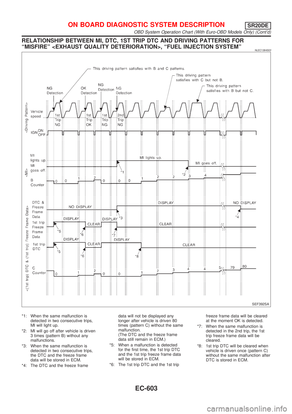
RELATIONSHIP BETWEEN MI, DTC, 1ST TRIP DTC AND DRIVING PATTERNS FOR
ªMISFIREº
NLEC1364S03
SEF392SA
*1: When the same malfunction is
detected in two consecutive trips,
MI will light up.
*2: MI will go off after vehicle is driven
3 times (pattern B) without any
malfunctions.
*3: When the same malfunction is
detected in two consecutive trips,
the DTC and the freeze frame
data will be stored in ECM.
*4: The DTC and the freeze framedata will not be displayed any
longer after vehicle is driven 80
times (pattern C) without the same
malfunction.
(The DTC and the freeze frame
data still remain in ECM.)
*5: When a malfunction is detected
for the first time, the 1st trip DTC
and the 1st trip freeze frame data
will be stored in ECM.
*6: The 1st trip DTC and the 1st tripfreeze frame data will be cleared
at the moment OK is detected.
*7: When the same malfunction is
detected in the 2nd trip, the 1st
trip freeze frame data will be
cleared.
*8: 1st trip DTC will be cleared when
vehicle is driven once (pattern C)
without the same malfunction after
DTC is stored in ECM.
ON BOARD DIAGNOSTIC SYSTEM DESCRIPTIONSR20DE
OBD System Operation Chart (With Euro-OBD Models Only) (Cont'd)
EC-603
Page 1029 of 3051
EXPLANATION FOR DRIVING PATTERNS FOR ªMISFIRE
NLEC1364S04Driving Pattern BNLEC1364S0401Driving pattern B means the vehicle operation as follows:
All components and systems should be monitored at least once by the OBD system.
+The B counter will be cleared when the malfunction is detected once regardless of the driving pattern.
+The B counter will be counted up when driving pattern B is satisfied without any malfunction.
+The MI will go off when the B counter reaches 3. (*2 in EC-603)
Driving Pattern CNLEC1364S0402Driving pattern C means the vehicle operation as follows:
1) The following conditions should be satisfied at the same time:
Engine speed: (Engine speed in the freeze frame data)±375 rpm
Calculated load value: (Calculated load value in the freeze frame data)´(1±0.1) [%]
Engine coolant temperature (T) condition:
+When the freeze frame data shows lower than 70ÉC (158ÉF), ªTº should be lower than 70ÉC (158ÉF).
+When the freeze frame data shows higher than or equal to 70ÉC (158ÉF), ªTº should be higher than or
equal to 70ÉC (158ÉF).
Example:
If the stored freeze frame data is as follows:
Engine speed: 850 rpm, Calculated load value: 30%, Engine coolant temperature: 80ÉC (176ÉF)
To be satisfied with driving pattern C, the vehicle should run under the following conditions:
Engine speed: 475 - 1,225 rpm, Calculated load value: 27 - 33%, Engine coolant temperature: more than 70ÉC
(158ÉF)
+The C counter will be cleared when the malfunction is detected regardless of driving pattern C.
+The C counter will be counted up when driving pattern C is satisfied without the same malfunction.
+The DTC will not be displayed after C counter reaches 80.
+The 1st trip DTC will be cleared when C counter is counted once without the same malfunction after DTC
is stored in ECM.
ON BOARD DIAGNOSTIC SYSTEM DESCRIPTIONSR20DE
OBD System Operation Chart (With Euro-OBD Models Only) (Cont'd)
EC-604
Page 1030 of 3051
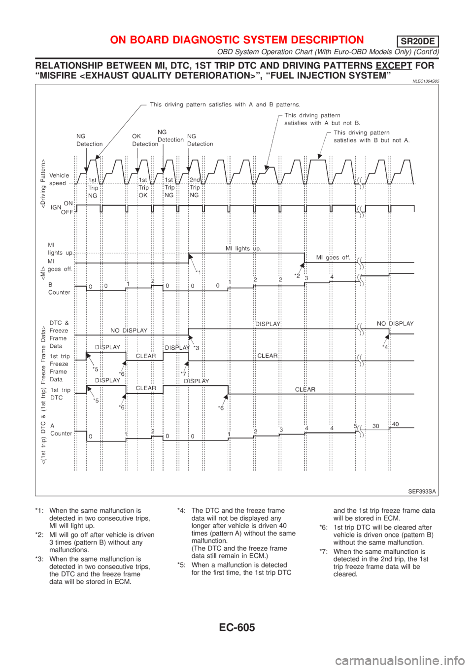
RELATIONSHIP BETWEEN MI, DTC, 1ST TRIP DTC AND DRIVING PATTERNS EXCEPTFOR
ªMISFIRE
NLEC1364S05
SEF393SA
*1: When the same malfunction is
detected in two consecutive trips,
MI will light up.
*2: MI will go off after vehicle is driven
3 times (pattern B) without any
malfunctions.
*3: When the same malfunction is
detected in two consecutive trips,
the DTC and the freeze frame
data will be stored in ECM.*4: The DTC and the freeze frame
data will not be displayed any
longer after vehicle is driven 40
times (pattern A) without the same
malfunction.
(The DTC and the freeze frame
data still remain in ECM.)
*5: When a malfunction is detected
for the first time, the 1st trip DTCand the 1st trip freeze frame data
will be stored in ECM.
*6: 1st trip DTC will be cleared after
vehicle is driven once (pattern B)
without the same malfunction.
*7: When the same malfunction is
detected in the 2nd trip, the 1st
trip freeze frame data will be
cleared.
ON BOARD DIAGNOSTIC SYSTEM DESCRIPTIONSR20DE
OBD System Operation Chart (With Euro-OBD Models Only) (Cont'd)
EC-605
Page 1031 of 3051
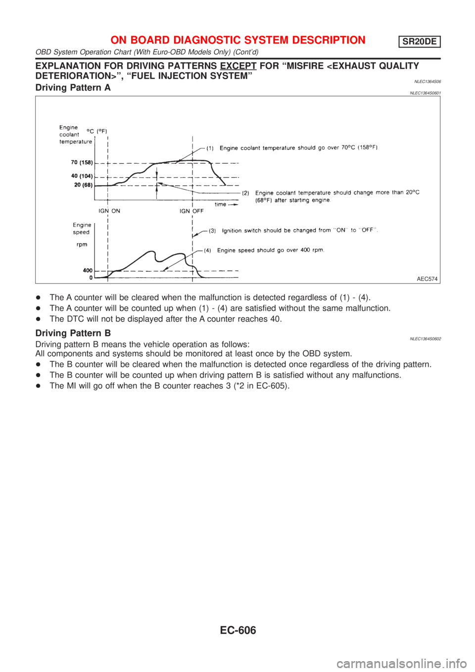
EXPLANATION FOR DRIVING PATTERNS EXCEPTFOR ªMISFIRE
NLEC1364S06Driving Pattern ANLEC1364S0601
AEC574
+The A counter will be cleared when the malfunction is detected regardless of (1) - (4).
+The A counter will be counted up when (1) - (4) are satisfied without the same malfunction.
+The DTC will not be displayed after the A counter reaches 40.
Driving Pattern BNLEC1364S0602Driving pattern B means the vehicle operation as follows:
All components and systems should be monitored at least once by the OBD system.
+The B counter will be cleared when the malfunction is detected once regardless of the driving pattern.
+The B counter will be counted up when driving pattern B is satisfied without any malfunctions.
+The MI will go off when the B counter reaches 3 (*2 in EC-605).
ON BOARD DIAGNOSTIC SYSTEM DESCRIPTIONSR20DE
OBD System Operation Chart (With Euro-OBD Models Only) (Cont'd)
EC-606
Page 1035 of 3051
7) Distance traveled while MI is activated.
8) Others
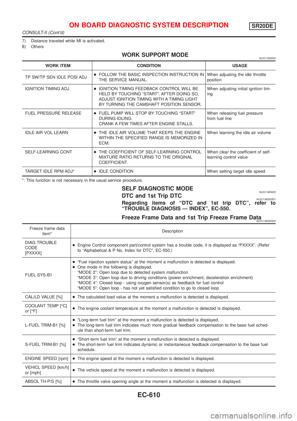
WORK SUPPORT MODENLEC1365S04
WORK ITEM CONDITION USAGE
TP SW/TP SEN IDLE POSI ADJ+FOLLOW THE BASIC INSPECTION INSTRUCTION IN
THE SERVICE MANUAL.When adjusting the idle throttle
position
IGNITION TIMING ADJ+IGNITION TIMING FEEDBACK CONTROL WILL BE
HELD BY TOUCHING ªSTARTº. AFTER DOING SO,
ADJUST IGNITION TIMING WITH A TIMING LIGHT
BY TURNING THE CAMSHAFT POSITION SENSOR.When adjusting initial ignition tim-
ing
FUEL PRESSURE RELEASE+FUEL PUMP WILL STOP BY TOUCHING ªSTARTº
DURING IDLING.
CRANK A FEW TIMES AFTER ENGINE STALLS.When releasing fuel pressure
from fuel line
IDLE AIR VOL LEARN+THE IDLE AIR VOLUME THAT KEEPS THE ENGINE
WITHIN THE SPECIFIED RANGE IS MEMORIZED IN
ECM.When learning the idle air volume
SELF-LEARNING CONT+THE COEFFICIENT OF SELF-LEARNING CONTROL
MIXTURE RATIO RETURNS TO THE ORIGINAL
COEFFICIENT.When clear the coefficient of self-
learning control value
TARGET IDLE RPM ADJ*+IDLE CONDITION When setting target idle speed
*: This function is not necessary in the usual service procedure.
SELF DIAGNOSTIC MODENLEC1365S05DTC and 1st Trip DTCNLEC1365S0501Regarding items of ªDTC and 1st trip DTCº, refer to
ªTROUBLE DIAGNOSIS Ð INDEXº, EC-550.
Freeze Frame Data and 1st Trip Freeze Frame DataNLEC1365S0502
Freeze frame data
item*Description
DIAG TROUBLE
CODE
[PXXXX]+Engine Control component part/control system has a trouble code, it is displayed as ªPXXXXº. (Refer
to ªAlphabetical & P No. Index for DTCº, EC-550.)
FUEL SYS-B1+ªFuel injection system statusº at the moment a malfunction is detected is displayed.
+One mode in the following is displayed.
ªMODE 2º: Open loop due to detected system malfunction
ªMODE 3º: Open loop due to driving conditions (power enrichment, deceleration enrichment)
ªMODE 4º: Closed loop - using oxygen sensor(s) as feedback for fuel control
ªMODE 5º: Open loop - has not yet satisfied condition to go to closed loop
CAL/LD VALUE [%]+The calculated load value at the moment a malfunction is detected is displayed.
COOLANT TEMP [ÉC]
or [ÉF]+The engine coolant temperature at the moment a malfunction is detected is displayed.
L-FUEL TRIM-B1 [%]+ªLong-term fuel trimº at the moment a malfunction is detected is displayed.
+The long-term fuel trim indicates much more gradual feedback compensation to the base fuel sched-
ule than short-term fuel trim.
S-FUEL TRIM-B1 [%]+ªShort-term fuel trimº at the moment a malfunction is detected is displayed.
+The short-term fuel trim indicates dynamic or instantaneous feedback compensation to the base fuel
schedule.
ENGINE SPEED [rpm]+The engine speed at the moment a malfunction is detected is displayed.
VEHICL SPEED [km/h]
or [mph]+The vehicle speed at the moment a malfunction is detected is displayed.
ABSOL TH´P/S [%]+The throttle valve opening angle at the moment a malfunction is detected is displayed.
ON BOARD DIAGNOSTIC SYSTEM DESCRIPTIONSR20DE
CONSULT-II (Cont'd)
EC-610
Page 1036 of 3051
![NISSAN ALMERA TINO 2001 Service Repair Manual Freeze frame data
item*Description
B/FUEL SCHDL [msec]+The base fuel schedule at the moment a malfunction is detected is displayed.
INT/A TEMP SE [ÉC]
or [ÉF]+The intake air temperature at the momen NISSAN ALMERA TINO 2001 Service Repair Manual Freeze frame data
item*Description
B/FUEL SCHDL [msec]+The base fuel schedule at the moment a malfunction is detected is displayed.
INT/A TEMP SE [ÉC]
or [ÉF]+The intake air temperature at the momen](/manual-img/5/57352/w960_57352-1035.png)
Freeze frame data
item*Description
B/FUEL SCHDL [msec]+The base fuel schedule at the moment a malfunction is detected is displayed.
INT/A TEMP SE [ÉC]
or [ÉF]+The intake air temperature at the moment a malfunction is detected is displayed.
*: The items are the same as those of 1st trip freeze frame data.
DATA MONITOR MODENLEC1365S06
Monitored item [Unit]ECM
input
signalsMain
signalsDescription Remarks
ENG SPEED [rpm]jj+Indicates the engine speed computed from
the REF signal (180É signal) of the camshaft
position sensor.
MAS A/F SE-B1 [V]jj+The signal voltage of the mass air flow sen-
sor is displayed.+When the engine is stopped, a cer-
tain value is indicated.
B/FUEL SCHDL
[msec]j+ªBase fuel scheduleº indicates the fuel injec-
tion pulse width programmed into ECM, prior
to any learned on board correction.
A/F ALPHA-B1 [%]j+Indicates the mean value of the air-fuel ratio
feedback correction factor per cycle.+When the engine is stopped, a cer-
tain value is indicated.
+This data also includes the data for
the air-fuel ratio learning control.
COOLAN TEMP/S
[ÉC] or [ÉF]jj+The engine coolant temperature (determined
by the signal voltage of the engine coolant
temperature sensor) is displayed.+When the engine coolant tempera-
ture sensor is open or short-
circuited, ECM enters fail-safe
mode. The engine coolant tempera-
ture determined by the ECM is dis-
played.
HO2S1 (B1) [V]jj+The signal voltage of the heated oxygen sen-
sor 1 (front) is displayed.
HO2S2 (B1) [V]jj+The signal voltage of the heated oxygen sen-
sor 2 (rear) is displayed.
HO2S1 MNTR (B1)
[RICH/LEAN]j+Display of heated oxygen sensor 1 (front)
signal during air-fuel ratio feedback control:
RICH ... means the mixture became ªrichº,
and control is being affected toward a leaner
mixture.
LEAN ... means the mixture became ªleanº,
and control is being affected toward a rich
mixture.+After turning ON the ignition switch,
ªRICHº is displayed until air-fuel mix-
ture ratio feedback control begins.
+When the air-fuel ratio feedback is
clamped, the value just before the
clamping is displayed continuously.
HO2S2 MNTR (B1)
[RICH/LEAN]j+Display of heated oxygen sensor 2 (rear) sig-
nal:
RICH ... means the amount of oxygen after
three way catalyst is relatively small.
LEAN ... means the amount of oxygen after
three way catalyst is relatively large.+When the engine is stopped, a cer-
tain value is indicated.
VHCL SPEED SE
[km/h] or [mph]jj+The vehicle speed computed from the vehicle
speed sensor signal is displayed.
BATTERY VOLT [V]jj+The power supply voltage of ECM is dis-
played.
THRTL POS SEN [V]jj+The throttle position sensor signal voltage is
displayed.
ON BOARD DIAGNOSTIC SYSTEM DESCRIPTIONSR20DE
CONSULT-II (Cont'd)
EC-611
Page 1037 of 3051
![NISSAN ALMERA TINO 2001 Service Repair Manual Monitored item [Unit]ECM
input
signalsMain
signalsDescription Remarks
INT/A TEMP SE
[ÉC] or [ÉF]jj+The intake air temperature determined by the
signal voltage of the intake air temperature
sensor is NISSAN ALMERA TINO 2001 Service Repair Manual Monitored item [Unit]ECM
input
signalsMain
signalsDescription Remarks
INT/A TEMP SE
[ÉC] or [ÉF]jj+The intake air temperature determined by the
signal voltage of the intake air temperature
sensor is](/manual-img/5/57352/w960_57352-1036.png)
Monitored item [Unit]ECM
input
signalsMain
signalsDescription Remarks
INT/A TEMP SE
[ÉC] or [ÉF]jj+The intake air temperature determined by the
signal voltage of the intake air temperature
sensor is indicated.
EGR TEMP SEN [V]
(where fitted)jj+The signal voltage of the EGR temperature
sensor is displayed.
START SIGNAL
[ON/OFF]jj+Indicates [ON/OFF] condition from the starter
signal.+After starting the engine, [OFF] is
displayed regardless of the starter
signal.
CLSD THL POS
[ON/OFF]jj+Indicates idle position [ON/OFF] computed by
ECM according to the throttle position sensor
signal.
AIR COND SIG
[ON/OFF]jj+Indicates [ON/OFF] condition of the air condi-
tioner switch as determined by the air condi-
tioning signal.
P/N POSI SW
[ON/OFF]jj+Indicates [ON/OFF] condition from the PNP
switch signal.
PW/ST SIGNAL
[ON/OFF]jj+Indicates [ON/OFF] condition of the power
steering oil pressure switch determined by
the power steering oil pressure switch signal.
LOAD SIGNAL
[ON/OFF]jj+Indicates [ON/OFF] condition from the electri-
cal load signal and/or lighting switch.
ON ... rear defogger is operating and/or light-
ing switch is on.
OFF ... rear defogger is not operating and
lighting switch is not on.
IGNITION SW
[ON/OFF]j+Indicates [ON/OFF] condition from ignition
switch.
INJ PULSE-B1
[msec]j+Indicates the actual fuel injection pulse width
compensated by ECM according to the input
signals.+When the engine is stopped, a cer-
tain computed value is indicated.
IGN TIMING [BTDC]j+Indicates the ignition timing computed by
ECM according to the input signals.
CAL/LD VALUE [%]+ªCalculated load valueº indicates the value of
the current airflow divided by peak airflow.
ABSOL TH.P/S [%]+ªAbsolute throttle position sensorº indicates
the throttle opening computed by ECM
according to the signal voltage of the throttle
position sensor.
MASS AIRFLOW
[gm/s]+Indicates the mass airflow computed by ECM
according to the signal voltage of the mass
air flow sensor.
IACV-AAC/V [step]j+Indicates the IACV-AAC valve control value
computed by ECM according to the input sig-
nals.
PURG VOL C/V [%]+Indicates the EVAP canister purge volume
control solenoid valve computed by the ECM
according to the inpuct signals.
+The opening becomes larger as the value
increases.
ON BOARD DIAGNOSTIC SYSTEM DESCRIPTIONSR20DE
CONSULT-II (Cont'd)
EC-612