2001 NISSAN ALMERA TINO display
[x] Cancel search: displayPage 1038 of 3051
![NISSAN ALMERA TINO 2001 Service Repair Manual Monitored item [Unit]ECM
input
signalsMain
signalsDescription Remarks
EGR VOL CON/V
[step] (where fitted)j+Indicates the EGR volume control valve com-
puted by the ECM according to the input sig-
nals NISSAN ALMERA TINO 2001 Service Repair Manual Monitored item [Unit]ECM
input
signalsMain
signalsDescription Remarks
EGR VOL CON/V
[step] (where fitted)j+Indicates the EGR volume control valve com-
puted by the ECM according to the input sig-
nals](/manual-img/5/57352/w960_57352-1037.png)
Monitored item [Unit]ECM
input
signalsMain
signalsDescription Remarks
EGR VOL CON/V
[step] (where fitted)j+Indicates the EGR volume control valve com-
puted by the ECM according to the input sig-
nals.
+The opening becomes larger as the value
increases.
AIR COND RLY
[ON/OFF]j+Indicates the air conditioner relay control con-
dition determined by ECM according to the
input signals.
FUEL PUMP RLY
[ON/OFF]j+Indicates the fuel pump relay control condi-
tion determined by ECM according to the
input signals.
COOLING FAN
[HIGH/LOW/OFF]+Indicates the control condition of the cooling
fan (determined by ECM according to the
input signal).
HIGH ... High speed operation
LOW ... Low speed operation
OFF ... Stop
HO2S1 HTR (B1)
[ON/OFF]+Indicates [ON/OFF] condition of heated oxy-
gen sensor 1 heater (front) determined by
ECM according to the input signals.
HO2S2 HTR (B1)
[ON/OFF]+Indicates [ON/OFF] condition of heated oxy-
gen sensor 2 heater (rear) determined by
ECM according to the input signals.
IDL A/V LEARN+Display the condition of idle air volume learn-
ing
YET ... Idle air volume learning has not been
performed yet.
CMPLT ... Idle air volume learning has
already been performed successfully.
INCMP ... Idle air volume learning has not
been performed successfully.
TRVL AFTER MIL
[km] or [Mile]+Distance traveled while MI is activated
VOLTAGE [V]+Voltage measured by the voltage probe.
PULSE
[msec] or [Hz] or [%]+Pulse width, frequency or duty cycle mea-
sured by the pulse probe.+Only ª#º is displayed if item is
unable to be measured.
+Figures with ª#ºs are temporary
ones. They are the same figures as
an actual piece of data which was
just previously measured.
NOTE:
Any monitored item that does not match the vehicle being diagnosed is deleted from the display automatically.
DATA MONITOR (SPEC) MODENLEC1365S07
Monitored item [Unit]ECM
input
signalsMain
signalsDescription Remarks
MAS A/F SE-B1 [V]jj+The signal voltage of the mass air flow sen-
sor specification is displayed.+When the engine is running, specifi-
cation range is indicated.
B/FUEL SCHDL
[msec]+ªBase fuel scheduleº indicates the fuel injec-
tion pulse width programmed into ECM, prior
to any learned on board correction.+When the engine is running, specifi-
cation range is indicated.
ON BOARD DIAGNOSTIC SYSTEM DESCRIPTIONSR20DE
CONSULT-II (Cont'd)
EC-613
Page 1039 of 3051
![NISSAN ALMERA TINO 2001 Service Repair Manual Monitored item [Unit]ECM
input
signalsMain
signalsDescription Remarks
A/F ALPHA-B1 [%]j+Indicates the mean value of the air-fuel ratio
feedback correction factor per cycle.+When the engine is running, NISSAN ALMERA TINO 2001 Service Repair Manual Monitored item [Unit]ECM
input
signalsMain
signalsDescription Remarks
A/F ALPHA-B1 [%]j+Indicates the mean value of the air-fuel ratio
feedback correction factor per cycle.+When the engine is running,](/manual-img/5/57352/w960_57352-1038.png)
Monitored item [Unit]ECM
input
signalsMain
signalsDescription Remarks
A/F ALPHA-B1 [%]j+Indicates the mean value of the air-fuel ratio
feedback correction factor per cycle.+When the engine is running, specifi-
cation range is indicated.
+This data also includes the data for
the air-fuel ratio learning control.
NOTE:
Any monitored item that does not match the vehicle being diagnosed is deleted from the display automatically.
ACTIVE TEST MODENLEC1365S08
TEST ITEM CONDITION JUDGEMENT CHECK ITEM (REMEDY)
FUEL INJEC-
TION+Engine: Return to the original
trouble condition
+Change the amount of fuel injec-
tion using CONSULT-II.If trouble symptom disappears, see
CHECK ITEM.+Harness and connector
+Fuel injectors
+Heated oxygen sensor 1 (front)
IGNITION TIM-
ING+Engine: Return to the original
trouble condition
+Timing light: Set
+Retard the ignition timing using
CONSULT-II.If trouble symptom disappears, see
CHECK ITEM.+Adjust initial ignition timing.
IACV-AAC/V
OPENING+Engine: After warming up, idle
the engine.
+Change the IACV-AAC valve
opening steps using CONSULT-
II.Engine speed changes according
to the opening steps.+Harness and connector
+IACV-AAC valve
POWER BAL-
ANCE+Engine: After warming up, idle
the engine.
+Air conditioner switch ªOFFº
+Shift lever ªNº
+Cut off each injector signal one
at a time using CONSULT-II.Engine runs rough or dies.+Harness and connector
+Compression
+Injectors
+Power transistor
+Spark plugs
+Ignition coil
+Ignition wires
COOLING FAN+Ignition switch: ON
+Turn the cooling fan ªHIGHº,
ªLOWº and ªOFFº using CON-
SULT-II.Cooling fan moves at high speed or
low speed and stops.+Harness and connector
+Cooling fan motors
+Cooling fan relays
ENG COOLANT
TEMP+Engine: Return to the original
trouble condition
+Change the engine coolant tem-
perature indication using CON-
SULT-II.If trouble symptom disappears, see
CHECK ITEM.+Harness and connector
+Engine coolant temperature sen-
sor
+Fuel injectors
FUEL PUMP
RELAY+Ignition switch: ON
(Engine stopped)
+Turn the fuel pump relay ªONº
and ªOFFº using CONSULT-II
and listen to operating sound.Fuel pump relay makes the operat-
ing sound.+Harness and connector
+Fuel pump relay
EGR VOL
CONT/V
(where fitted)+Engine: After warming up, idle
the engine.
+Change the EGR volume control
valve opening step using CON-
SULT-II.EGR volume control valve maks an
operating sound.+Harness and connector
+EGR volume control valve
ON BOARD DIAGNOSTIC SYSTEM DESCRIPTIONSR20DE
CONSULT-II (Cont'd)
EC-614
Page 1040 of 3051
TEST ITEM CONDITION JUDGEMENT CHECK ITEM (REMEDY)
PURG VOL
CONT/V+Engine: After warming up, idle
the engine.
+Change the EVAP canister purge
volume control solenoid valve
opening percent using CON-
SULT-II.Engine speed changes according
to the opening percent.+Harness and connector
+EVAP canister purge volume
control solenoid valve
DTC AND SRT CONFIRMATION MODENLEC1365S09This mode is not available for models without Euro-OBD system.
SRT STATUS ModeNLEC1365S0901For details, refer to ªSYSTEM READINESS TEST (SRT) CODEº,
EC-586.
SRT Work Support ModeNLEC1365S0902This mode enables a technician to drive a vehicle to set the SRT
while monitoring the SRT status.
DTC Work Support ModeNLEC1365S0903
TEST MODE TEST ITEM CONDITION REFERENCE PAGE
HEATED OXYGEN
SENSOR 1 (FRONT)HO2S1 (B1) P0130
Refer to corresponding
trouble diagnosis for DTC.EC-709
HO2S1 (B1) P0131 EC-717
HO2S1 (B1) P0132 EC-723
HO2S1 (B1) P0133 EC-729
HEATED OXYGEN
SENSOR 2 (REAR)HO2S2 (B1) P0137 EC-752
HO2S2 (B1) P0138 EC-761
HO2S2 (B1) P0139 EC-770
EGR SYSTEM
(where fitted)EGR SYSTEM P0400 EC-834
EGR SYSTEM P1402 EC-921
SEF705Y
SEF707X
REAL TIME DIAGNOSIS IN DATA MONITOR MODE
(RECORDING VEHICLE DATA)
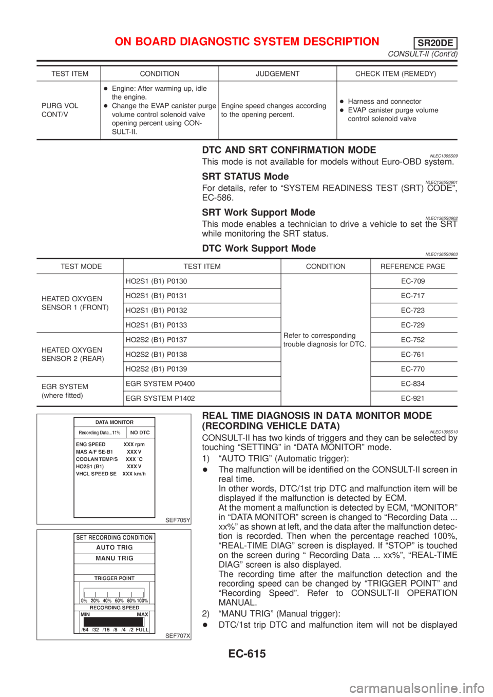
NLEC1365S10CONSULT-II has two kinds of triggers and they can be selected by
touching ªSETTINGº in ªDATA MONITORº mode.
1) ªAUTO TRIGº (Automatic trigger):
+The malfunction will be identified on the CONSULT-II screen in
real time.
In other words, DTC/1st trip DTC and malfunction item will be
displayed if the malfunction is detected by ECM.
At the moment a malfunction is detected by ECM, ªMONITORº
in ªDATA MONITORº screen is changed to ªRecording Data ...
xx%º as shown at left, and the data after the malfunction detec-
tion is recorded. Then when the percentage reached 100%,
ªREAL-TIME DIAGº screen is displayed. If ªSTOPº is touched
on the screen during ª Recording Data ... xx%º, ªREAL-TIME
DIAGº screen is also displayed.
The recording time after the malfunction detection and the
recording speed can be changed by ªTRIGGER POINTº and
ªRecording Speedº. Refer to CONSULT-II OPERATION
MANUAL.
2) ªMANU TRIGº (Manual trigger):
+DTC/1st trip DTC and malfunction item will not be displayed
ON BOARD DIAGNOSTIC SYSTEM DESCRIPTIONSR20DE
CONSULT-II (Cont'd)
EC-615
Page 1041 of 3051
automatically on CONSULT-II screen even though a malfunc-
tion is detected by ECM.
DATA MONITOR can be performed continuously even though
a malfunction is detected.
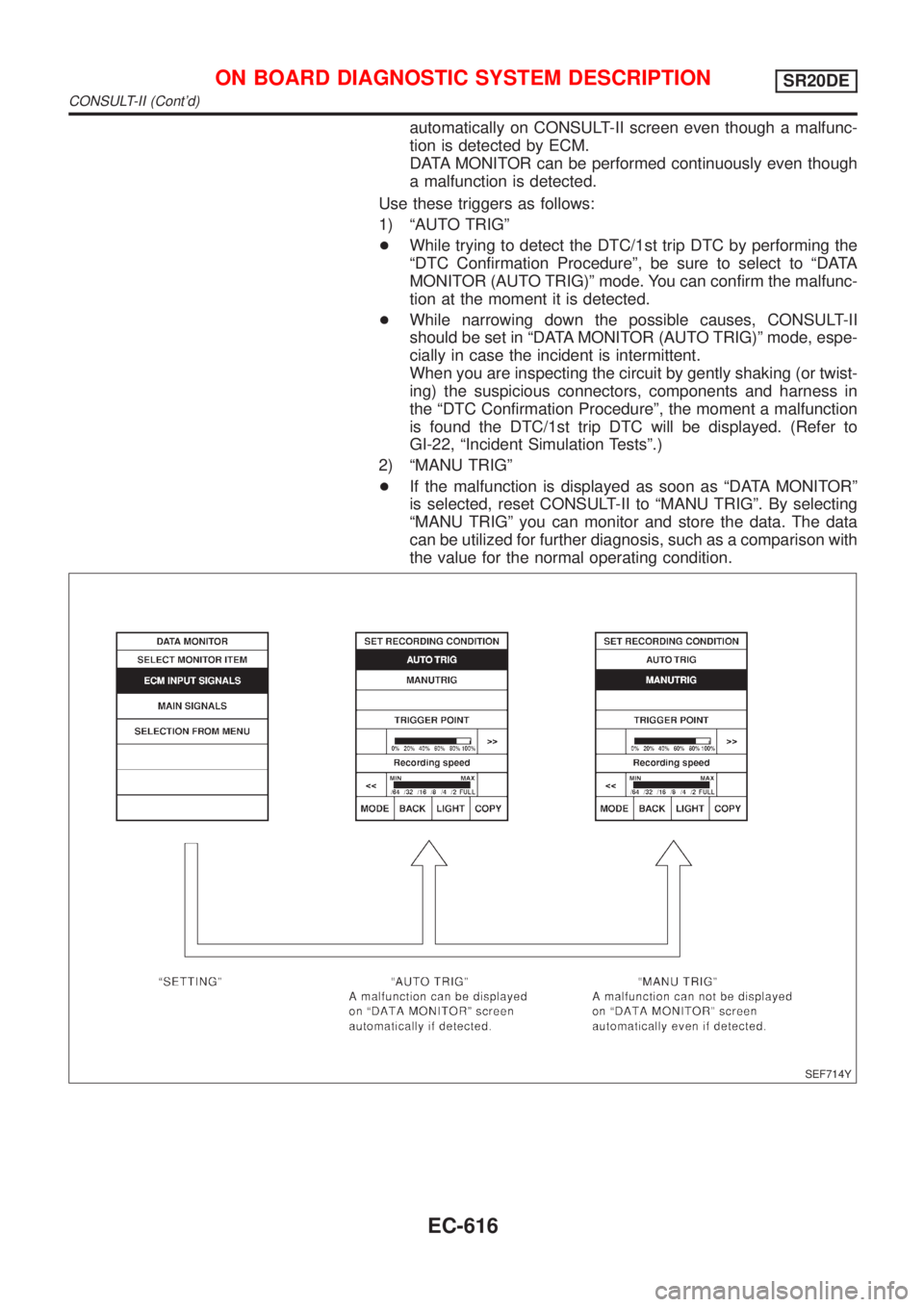
Use these triggers as follows:
1) ªAUTO TRIGº
+While trying to detect the DTC/1st trip DTC by performing the
ªDTC Confirmation Procedureº, be sure to select to ªDATA
MONITOR (AUTO TRIG)º mode. You can confirm the malfunc-
tion at the moment it is detected.
+While narrowing down the possible causes, CONSULT-II
should be set in ªDATA MONITOR (AUTO TRIG)º mode, espe-
cially in case the incident is intermittent.
When you are inspecting the circuit by gently shaking (or twist-
ing) the suspicious connectors, components and harness in
the ªDTC Confirmation Procedureº, the moment a malfunction
is found the DTC/1st trip DTC will be displayed. (Refer to
GI-22, ªIncident Simulation Testsº.)
2) ªMANU TRIGº
+If the malfunction is displayed as soon as ªDATA MONITORº
is selected, reset CONSULT-II to ªMANU TRIGº. By selecting
ªMANU TRIGº you can monitor and store the data. The data
can be utilized for further diagnosis, such as a comparison with
the value for the normal operating condition.
SEF714Y
ON BOARD DIAGNOSTIC SYSTEM DESCRIPTIONSR20DE
CONSULT-II (Cont'd)
EC-616
Page 1047 of 3051
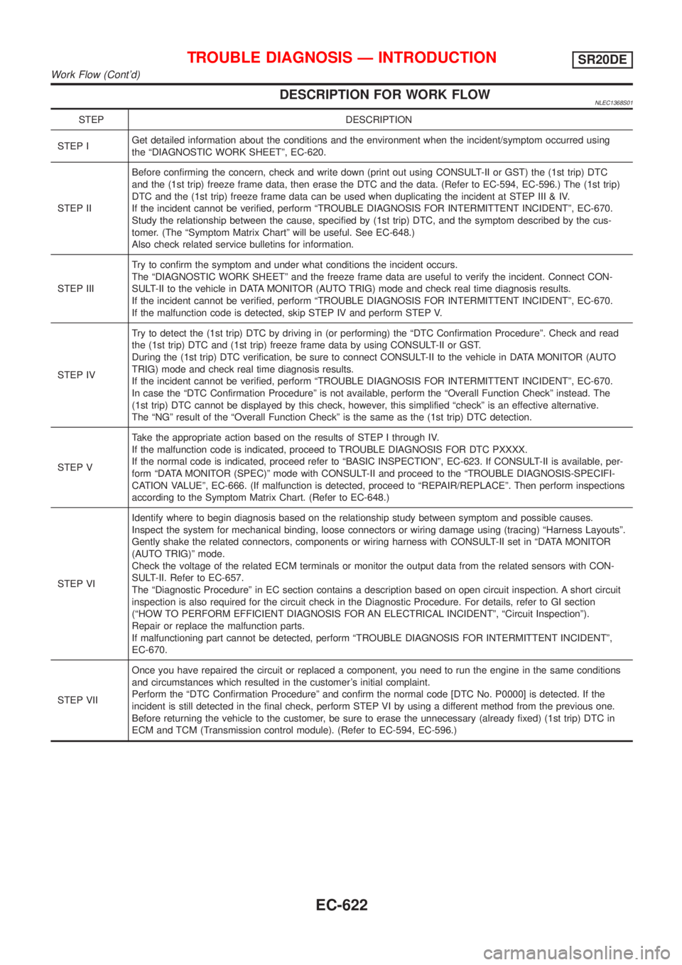
DESCRIPTION FOR WORK FLOWNLEC1368S01
STEP DESCRIPTION
STEP IGet detailed information about the conditions and the environment when the incident/symptom occurred using
the ªDIAGNOSTIC WORK SHEETº, EC-620.
STEP IIBefore confirming the concern, check and write down (print out using CONSULT-II or GST) the (1st trip) DTC
and the (1st trip) freeze frame data, then erase the DTC and the data. (Refer to EC-594, EC-596.) The (1st trip)
DTC and the (1st trip) freeze frame data can be used when duplicating the incident at STEP III & IV.
If the incident cannot be verified, perform ªTROUBLE DIAGNOSIS FOR INTERMITTENT INCIDENTº, EC-670.
Study the relationship between the cause, specified by (1st trip) DTC, and the symptom described by the cus-
tomer. (The ªSymptom Matrix Chartº will be useful. See EC-648.)
Also check related service bulletins for information.
STEP IIITry to confirm the symptom and under what conditions the incident occurs.
The ªDIAGNOSTIC WORK SHEETº and the freeze frame data are useful to verify the incident. Connect CON-
SULT-II to the vehicle in DATA MONITOR (AUTO TRIG) mode and check real time diagnosis results.
If the incident cannot be verified, perform ªTROUBLE DIAGNOSIS FOR INTERMITTENT INCIDENTº, EC-670.
If the malfunction code is detected, skip STEP IV and perform STEP V.
STEP IVTry to detect the (1st trip) DTC by driving in (or performing) the ªDTC Confirmation Procedureº. Check and read
the (1st trip) DTC and (1st trip) freeze frame data by using CONSULT-II or GST.
During the (1st trip) DTC verification, be sure to connect CONSULT-II to the vehicle in DATA MONITOR (AUTO
TRIG) mode and check real time diagnosis results.
If the incident cannot be verified, perform ªTROUBLE DIAGNOSIS FOR INTERMITTENT INCIDENTº, EC-670.
In case the ªDTC Confirmation Procedureº is not available, perform the ªOverall Function Checkº instead. The
(1st trip) DTC cannot be displayed by this check, however, this simplified ªcheckº is an effective alternative.
The ªNGº result of the ªOverall Function Checkº is the same as the (1st trip) DTC detection.
STEP VTake the appropriate action based on the results of STEP I through IV.
If the malfunction code is indicated, proceed to TROUBLE DIAGNOSIS FOR DTC PXXXX.
If the normal code is indicated, proceed refer to ªBASIC INSPECTIONº, EC-623. If CONSULT-II is available, per-
form ªDATA MONITOR (SPEC)º mode with CONSULT-II and proceed to the ªTROUBLE DIAGNOSIS-SPECIFI-
CATION VALUEº, EC-666. (If malfunction is detected, proceed to ªREPAIR/REPLACEº. Then perform inspections
according to the Symptom Matrix Chart. (Refer to EC-648.)
STEP VIIdentify where to begin diagnosis based on the relationship study between symptom and possible causes.
Inspect the system for mechanical binding, loose connectors or wiring damage using (tracing) ªHarness Layoutsº.
Gently shake the related connectors, components or wiring harness with CONSULT-II set in ªDATA MONITOR
(AUTO TRIG)º mode.
Check the voltage of the related ECM terminals or monitor the output data from the related sensors with CON-
SULT-II. Refer to EC-657.
The ªDiagnostic Procedureº in EC section contains a description based on open circuit inspection. A short circuit
inspection is also required for the circuit check in the Diagnostic Procedure. For details, refer to GI section
(ªHOW TO PERFORM EFFICIENT DIAGNOSIS FOR AN ELECTRICAL INCIDENTº, ªCircuit Inspectionº).
Repair or replace the malfunction parts.
If malfunctioning part cannot be detected, perform ªTROUBLE DIAGNOSIS FOR INTERMITTENT INCIDENTº,
EC-670.
STEP VIIOnce you have repaired the circuit or replaced a component, you need to run the engine in the same conditions
and circumstances which resulted in the customer's initial complaint.
Perform the ªDTC Confirmation Procedureº and confirm the normal code [DTC No. P0000] is detected. If the
incident is still detected in the final check, perform STEP VI by using a different method from the previous one.
Before returning the vehicle to the customer, be sure to erase the unnecessary (already fixed) (1st trip) DTC in
ECM and TCM (Transmission control module). (Refer to EC-594, EC-596.)
TROUBLE DIAGNOSIS Ð INTRODUCTIONSR20DE
Work Flow (Cont'd)
EC-622
Page 1062 of 3051
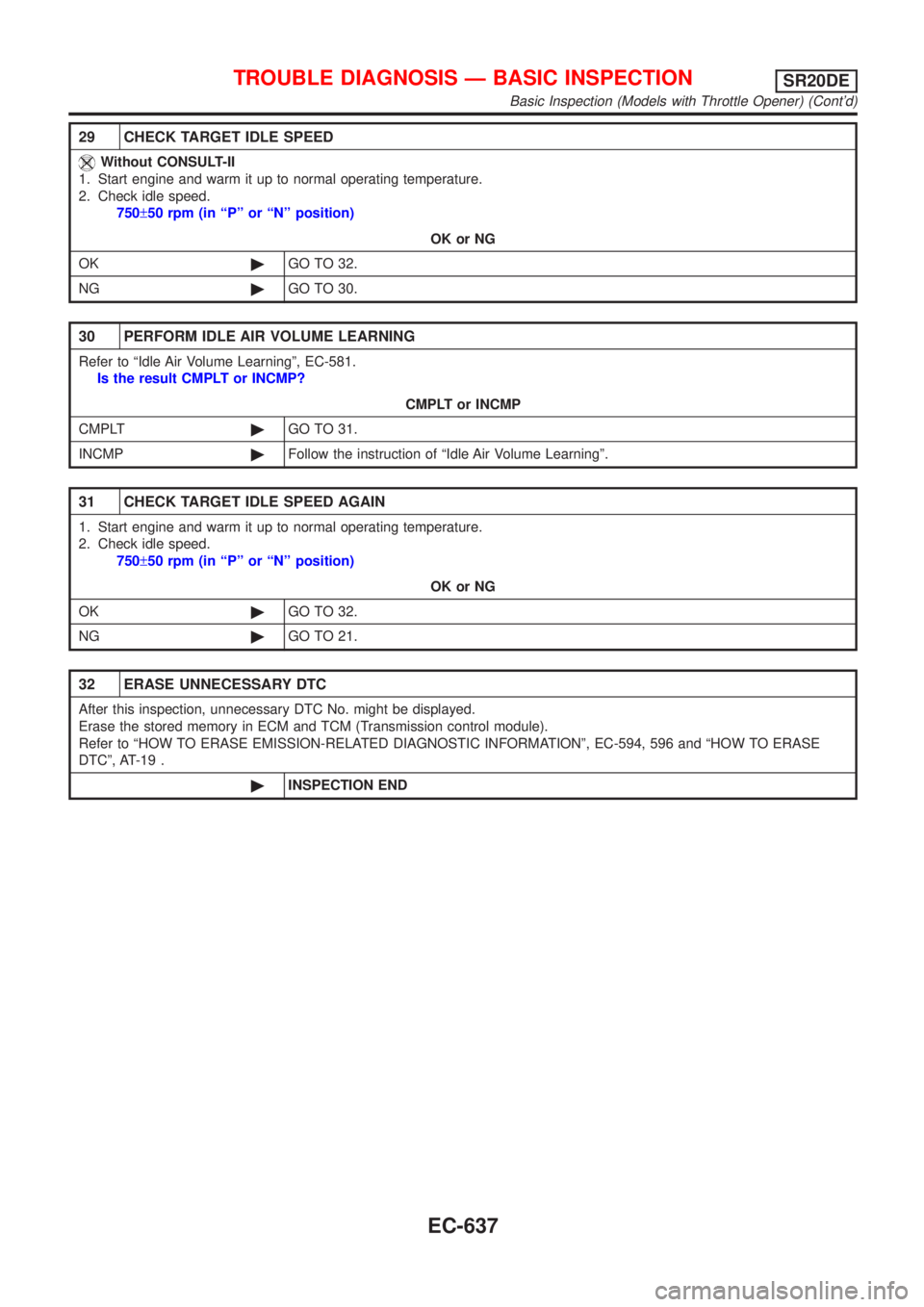
29 CHECK TARGET IDLE SPEED
Without CONSULT-II
1. Start engine and warm it up to normal operating temperature.
2. Check idle speed.
750±50 rpm (in ªPº or ªNº position)
OK or NG
OK©GO TO 32.
NG©GO TO 30.
30 PERFORM IDLE AIR VOLUME LEARNING
Refer to ªIdle Air Volume Learningº, EC-581.
Is the result CMPLT or INCMP?
CMPLT or INCMP
CMPLT©GO TO 31.
INCMP©Follow the instruction of ªIdle Air Volume Learningº.
31 CHECK TARGET IDLE SPEED AGAIN
1. Start engine and warm it up to normal operating temperature.
2. Check idle speed.
750±50 rpm (in ªPº or ªNº position)
OK or NG
OK©GO TO 32.
NG©GO TO 21.
32 ERASE UNNECESSARY DTC
After this inspection, unnecessary DTC No. might be displayed.
Erase the stored memory in ECM and TCM (Transmission control module).
Refer to ªHOW TO ERASE EMISSION-RELATED DIAGNOSTIC INFORMATIONº, EC-594, 596 and ªHOW TO ERASE
DTCº, AT-19 .
©INSPECTION END
TROUBLE DIAGNOSIS Ð BASIC INSPECTIONSR20DE
Basic Inspection (Models with Throttle Opener) (Cont'd)
EC-637
Page 1066 of 3051
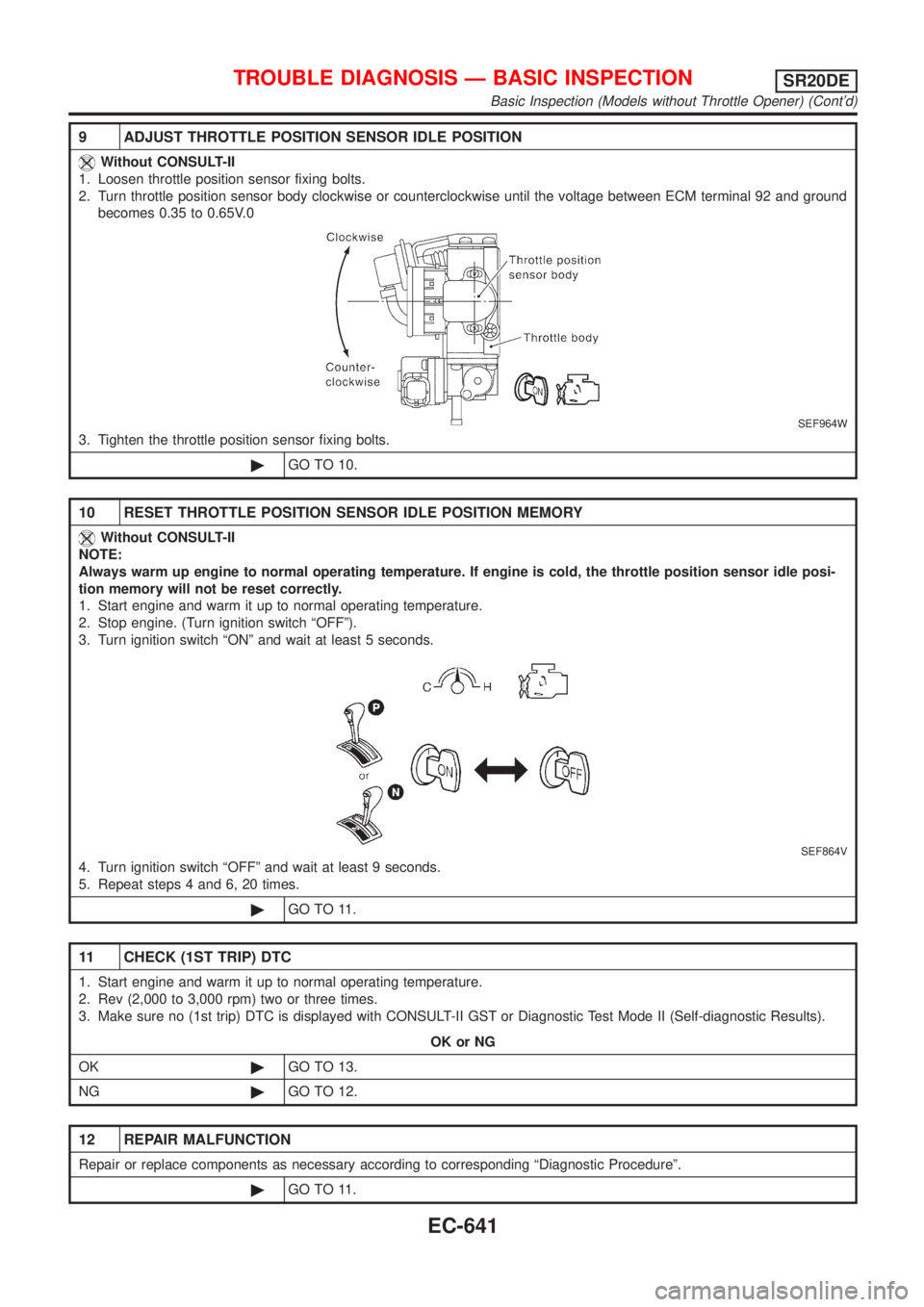
9 ADJUST THROTTLE POSITION SENSOR IDLE POSITION
Without CONSULT-II
1. Loosen throttle position sensor fixing bolts.
2. Turn throttle position sensor body clockwise or counterclockwise until the voltage between ECM terminal 92 and ground
becomes 0.35 to 0.65V.0
SEF964W
3. Tighten the throttle position sensor fixing bolts.
©GO TO 10.
10 RESET THROTTLE POSITION SENSOR IDLE POSITION MEMORY
Without CONSULT-II
NOTE:
Always warm up engine to normal operating temperature. If engine is cold, the throttle position sensor idle posi-
tion memory will not be reset correctly.
1. Start engine and warm it up to normal operating temperature.
2. Stop engine. (Turn ignition switch ªOFFº).
3. Turn ignition switch ªONº and wait at least 5 seconds.
SEF864V
4. Turn ignition switch ªOFFº and wait at least 9 seconds.
5. Repeat steps 4 and 6, 20 times.
©GO TO 11.
11 CHECK (1ST TRIP) DTC
1. Start engine and warm it up to normal operating temperature.
2. Rev (2,000 to 3,000 rpm) two or three times.
3. Make sure no (1st trip) DTC is displayed with CONSULT-II GST or Diagnostic Test Mode II (Self-diagnostic Results).
OK or NG
OK©GO TO 13.
NG©GO TO 12.
12 REPAIR MALFUNCTION
Repair or replace components as necessary according to corresponding ªDiagnostic Procedureº.
©GO TO 11.
TROUBLE DIAGNOSIS Ð BASIC INSPECTIONSR20DE
Basic Inspection (Models without Throttle Opener) (Cont'd)
EC-641
Page 1070 of 3051
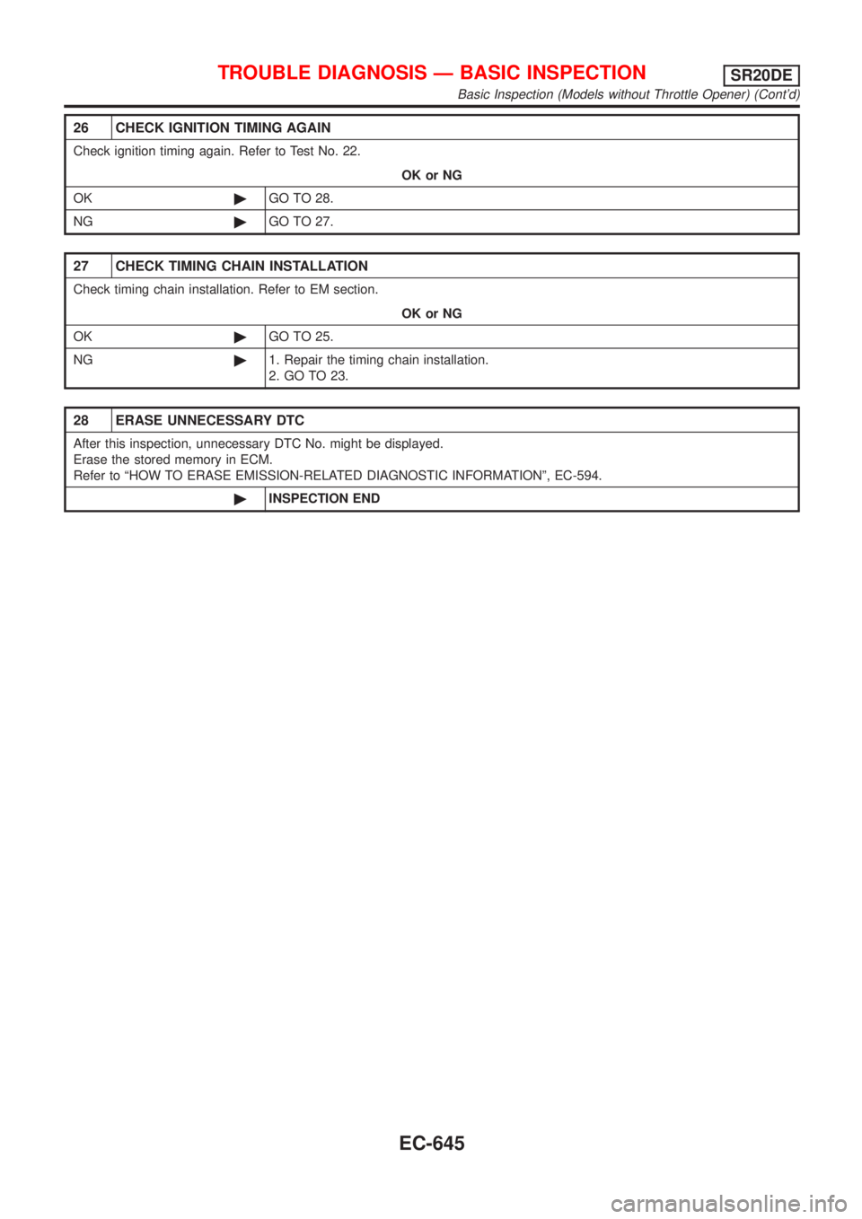
26 CHECK IGNITION TIMING AGAIN
Check ignition timing again. Refer to Test No. 22.
OK or NG
OK©GO TO 28.
NG©GO TO 27.
27 CHECK TIMING CHAIN INSTALLATION
Check timing chain installation. Refer to EM section.
OK or NG
OK©GO TO 25.
NG©1. Repair the timing chain installation.
2. GO TO 23.
28 ERASE UNNECESSARY DTC
After this inspection, unnecessary DTC No. might be displayed.
Erase the stored memory in ECM.
Refer to ªHOW TO ERASE EMISSION-RELATED DIAGNOSTIC INFORMATIONº, EC-594.
©INSPECTION END
TROUBLE DIAGNOSIS Ð BASIC INSPECTIONSR20DE
Basic Inspection (Models without Throttle Opener) (Cont'd)
EC-645