Page 1477 of 2898
10 CHECK COOLING FAN MOTORS-1 AND -2
Supply battery voltage between the following terminals and check operation.
SEF902Y
OK or NG
OK©GO TO 11.
NG©Replace cooling fan motors.
11 CHECK INTERMITTENT INCIDENT
Perform ªTROUBLE DIAGNOSIS FOR INTERMITTENT INCIDENTº, EC-665.
©INSPECTION END
Procedure BNJEC0666S0402
1 CHECK COOLING FAN POWER SUPPLY CIRCUIT
1. Turn ignition switch ªOFFº.
2. Disconnect cooling fan relays-2, 3 and 4.
SEF384Y
3. Turn ignition switch ªONº.
4. Check voltage between cooling fan relays-2, 4 terminals 1 and ground, cooling fan relay-3 terminals 2, 3 and ground
with CONSULT-II or tester.
SEF903Y
OK or NG
OK©GO TO 3.
NG©GO TO 2.
DTC P1217 OVER HEATYD
Diagnostic Procedure (Cont'd)
EC-753
Page 1478 of 2898
2 DETECT MALFUNCTIONING PART
Check the following.
+40A fusible link
+Harness for open or short between cooling fan relays-2, 3, 4 and fuse
+Harness for open or short between cooling fan relay-3 and fusible link
©Repair harness or connectors.
3 CHECK COOLING FAN GROUND CIRCUIT FOR OPEN AND SHORT
1. Turn ignition switch ªOFFº.
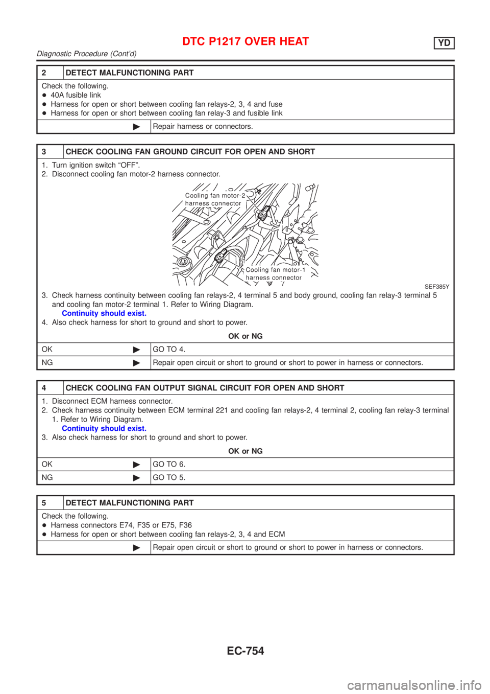
2. Disconnect cooling fan motor-2 harness connector.
SEF385Y
3. Check harness continuity between cooling fan relays-2, 4 terminal 5 and body ground, cooling fan relay-3 terminal 5
and cooling fan motor-2 terminal 1. Refer to Wiring Diagram.
Continuity should exist.
4. Also check harness for short to ground and short to power.
OK or NG
OK©GO TO 4.
NG©Repair open circuit or short to ground or short to power in harness or connectors.
4 CHECK COOLING FAN OUTPUT SIGNAL CIRCUIT FOR OPEN AND SHORT
1. Disconnect ECM harness connector.
2. Check harness continuity between ECM terminal 221 and cooling fan relays-2, 4 terminal 2, cooling fan relay-3 terminal
1. Refer to Wiring Diagram.
Continuity should exist.
3. Also check harness for short to ground and short to power.
OK or NG
OK©GO TO 6.
NG©GO TO 5.
5 DETECT MALFUNCTIONING PART
Check the following.
+Harness connectors E74, F35 or E75, F36
+Harness for open or short between cooling fan relays-2, 3, 4 and ECM
©Repair open circuit or short to ground or short to power in harness or connectors.
DTC P1217 OVER HEATYD
Diagnostic Procedure (Cont'd)
EC-754
Page 1479 of 2898
6 CHECK COOLING FAN RELAYS-2 AND -4
Check continuity between cooling fan relay-2, -3 terminals 3 and 4, 3 and 5 under the following conditions.
SEF900Y
OK or NG
OK©GO TO 7.
NG©Replace cooling fan relays.
7 CHECK COOLING FAN RELAY-3
Check continuity between cooling fan relay-3 terminals 3 and 5 under the following conditions.
SEF901Y
OK or NG
OK©GO TO 8.
NG©Replace cooling fan relay.
8 CHECK COOLING FAN MOTORS
Supply battery voltage between the following terminals and check operation.
SEF902Y
OK or NG
OK©GO TO 9.
NG©Replace cooling fan motors.
DTC P1217 OVER HEATYD
Diagnostic Procedure (Cont'd)
EC-755
Page 1480 of 2898
9 CHECK INTERMITTENT INCIDENT
1. Perform ªTROUBLE DIAGNOSIS FOR INTERMITTENT INCIDENTº, EC-665.
©INSPECTION END
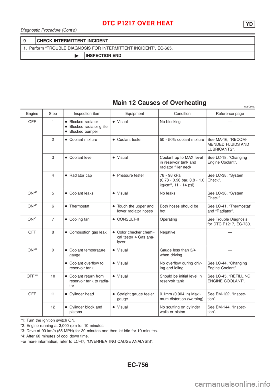
Main 12 Causes of OverheatingNJEC0667
Engine Step Inspection item Equipment Condition Reference page
OFF 1+Blocked radiator
+Blocked radiator grille
+Blocked bumper+Visual No blocking Ð
2+Coolant mixture+Coolant tester 50 - 50% coolant mixture See MA-16, ªRECOM-
MENDED FLUIDS AND
LUBRICANTSº.
3+Coolant level+Visual Coolant up to MAX level
in reservoir tank and
radiator filler neckSee LC-18, ªChanging
Engine Coolantº.
4+Radiator cap+Pressure tester 78 - 98 kPa
(0.78 - 0.98 bar, 0.8 - 1.0
kg/cm
2, 11 - 14 psi)See LC-38, ªSystem
Checkº.
ON*
25+Coolant leaks+Visual No leaks See LC-38, ªSystem
Checkº.
ON*
26+Thermostat+Touch the upper and
lower radiator hosesBoth hoses should be
hotSee LC-41, ªThermostatº
and ªRadiatorº.
ON*
17+Cooling fan+CONSULT-II Operating See Trouble Diagnosis
for DTC P1217, EC-730.
OFF 8+Combustion gas leak+Color checker chemi-
cal tester 4 Gas ana-
lyzerNegative Ð
ON*
39+Coolant temperature
gauge+Visual Gauge less than 3/4
when drivingÐ
+Coolant overflow to
reservoir tank+Visual No overflow during driv-
ing and idlingSee LC-44, ªChanging
Engine Coolantº.
OFF*
410+Coolant return from
reservoir tank to radia-
tor+Visual Should be initial level in
reservoir tankSee LC-45, ªREFILLING
ENGINE COOLANTº.
OFF 11+Cylinder head+Straight gauge feeler
gauge0.1mm (0.004 in) Maxi-
mum distortion (warping)See EM-122, ªInspec-
tionº.
12+Cylinder block and
pistons+Visual No scuffing on cylinder
walls or pistonSee EM-144, ªInspec-
tionº.
*1: Turn the ignition switch ON.
*2: Engine running at 3,000 rpm for 10 minutes.
*3: Drive at 90 km/h (55 MPH) for 30 minutes and then let idle for 10 minutes.
*4: After 60 minutes of cool down time.
For more information, refer to LC-47, ªOVERHEATING CAUSE ANALYSISº.
DTC P1217 OVER HEATYD
Diagnostic Procedure (Cont'd)
EC-756
Page 2133 of 2898
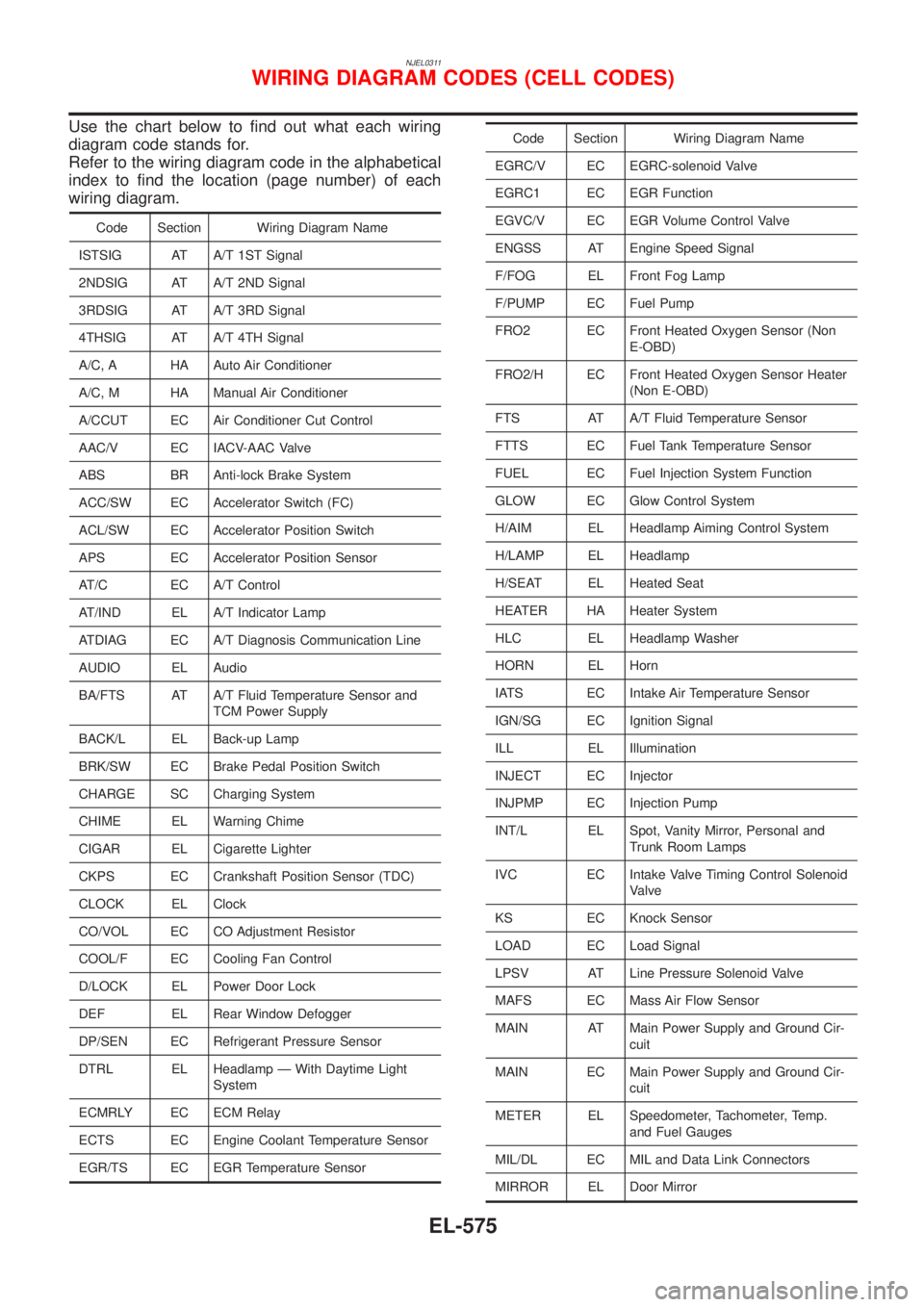
NJEL0311
Use the chart below to find out what each wiring
diagram code stands for.
Refer to the wiring diagram code in the alphabetical
index to find the location (page number) of each
wiring diagram.
Code Section Wiring Diagram Name
ISTSIG AT A/T 1ST Signal
2NDSIG AT A/T 2ND Signal
3RDSIG AT A/T 3RD Signal
4THSIG AT A/T 4TH Signal
A/C, A HA Auto Air Conditioner
A/C, M HA Manual Air Conditioner
A/CCUT EC Air Conditioner Cut Control
AAC/V EC IACV-AAC Valve
ABS BR Anti-lock Brake System
ACC/SW EC Accelerator Switch (FC)
ACL/SW EC Accelerator Position Switch
APS EC Accelerator Position Sensor
AT/C EC A/T Control
AT/IND EL A/T Indicator Lamp
ATDIAG EC A/T Diagnosis Communication Line
AUDIO EL Audio
BA/FTS AT A/T Fluid Temperature Sensor and
TCM Power Supply
BACK/L EL Back-up Lamp
BRK/SW EC Brake Pedal Position Switch
CHARGE SC Charging System
CHIME EL Warning Chime
CIGAR EL Cigarette Lighter
CKPS EC Crankshaft Position Sensor (TDC)
CLOCK EL Clock
CO/VOL EC CO Adjustment Resistor
COOL/F EC Cooling Fan Control
D/LOCK EL Power Door Lock
DEF EL Rear Window Defogger
DP/SEN EC Refrigerant Pressure Sensor
DTRL EL Headlamp Ð With Daytime Light
System
ECMRLY EC ECM Relay
ECTS EC Engine Coolant Temperature Sensor
EGR/TS EC EGR Temperature Sensor
Code Section Wiring Diagram Name
EGRC/V EC EGRC-solenoid Valve
EGRC1 EC EGR Function
EGVC/V EC EGR Volume Control Valve
ENGSS AT Engine Speed Signal
F/FOG EL Front Fog Lamp
F/PUMP EC Fuel Pump
FRO2 EC Front Heated Oxygen Sensor (Non
E-OBD)
FRO2/H EC Front Heated Oxygen Sensor Heater
(Non E-OBD)
FTS AT A/T Fluid Temperature Sensor
FTTS EC Fuel Tank Temperature Sensor
FUEL EC Fuel Injection System Function
GLOW EC Glow Control System
H/AIM EL Headlamp Aiming Control System
H/LAMP EL Headlamp
H/SEAT EL Heated Seat
HEATER HA Heater System
HLC EL Headlamp Washer
HORN EL Horn
IATS EC Intake Air Temperature Sensor
IGN/SG EC Ignition Signal
ILL EL Illumination
INJECT EC Injector
INJPMP EC Injection Pump
INT/L EL Spot, Vanity Mirror, Personal and
Trunk Room Lamps
IVC EC Intake Valve Timing Control Solenoid
Valve
KS EC Knock Sensor
LOAD EC Load Signal
LPSV AT Line Pressure Solenoid Valve
MAFS EC Mass Air Flow Sensor
MAIN AT Main Power Supply and Ground Cir-
cuit
MAIN EC Main Power Supply and Ground Cir-
cuit
METER EL Speedometer, Tachometer, Temp.
and Fuel Gauges
MIL/DL EC MIL and Data Link Connectors
MIRROR EL Door Mirror
WIRING DIAGRAM CODES (CELL CODES)
EL-575
Page 2187 of 2898
SEM174D
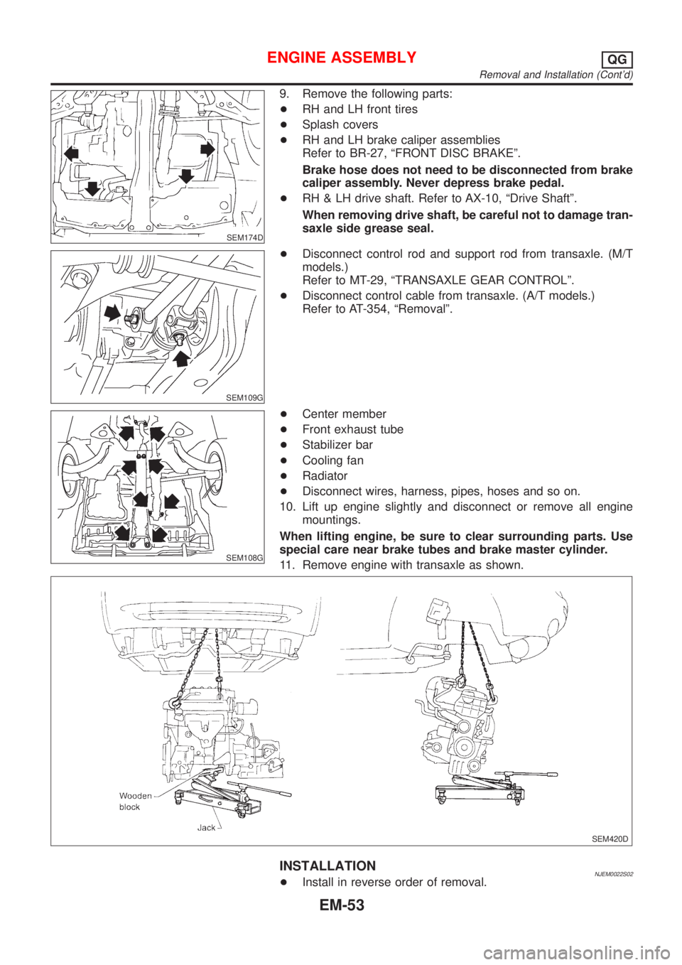
9. Remove the following parts:
+RH and LH front tires
+Splash covers
+RH and LH brake caliper assemblies
Refer to BR-27, ªFRONT DISC BRAKEº.
Brake hose does not need to be disconnected from brake
caliper assembly. Never depress brake pedal.
+RH & LH drive shaft. Refer to AX-10, ªDrive Shaftº.
When removing drive shaft, be careful not to damage tran-
saxle side grease seal.
SEM109G
+Disconnect control rod and support rod from transaxle. (M/T
models.)
Refer to MT-29, ªTRANSAXLE GEAR CONTROLº.
+Disconnect control cable from transaxle. (A/T models.)
Refer to AT-354, ªRemovalº.
SEM108G
+Center member
+Front exhaust tube
+Stabilizer bar
+Cooling fan
+Radiator
+Disconnect wires, harness, pipes, hoses and so on.
10. Lift up engine slightly and disconnect or remove all engine
mountings.
When lifting engine, be sure to clear surrounding parts. Use
special care near brake tubes and brake master cylinder.
11. Remove engine with transaxle as shown.
SEM420D
INSTALLATIONNJEM0022S02+Install in reverse order of removal.
ENGINE ASSEMBLYQG
Removal and Installation (Cont'd)
EM-53
Page 2220 of 2898
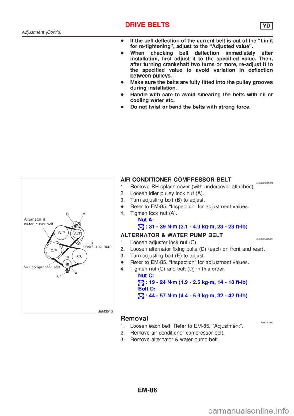
+If the belt deflection of the current belt is out of the ªLimit
for re-tighteningº, adjust to the ªAdjusted valueº.
+When checking belt deflection immediately after
installation, first adjust it to the specified value. Then,
after turning crankshaft two turns or more, re-adjust it to
the specified value to avoid variation in deflection
between pulleys.
+Make sure the belts are fully fitted into the pulley grooves
during installation.
+Handle with care to avoid smearing the belts with oil or
cooling water etc.
+Do not twist or bend the belts with strong force.
JEM251G
AIR CONDITIONER COMPRESSOR BELTNJEM0089S011. Remove RH splash cover (with undercover attached).
2. Loosen idler pulley lock nut (A).
3. Turn adjusting bolt (B) to adjust.
+Refer to EM-85, ªInspectionº for adjustment values.
4. Tighten lock nut (A).
Nut A:
: 31 - 39 N´m (3.1 - 4.0 kg-m, 23 - 28 ft-lb)
ALTERNATOR & WATER PUMP BELTNJEM0089S021. Loosen adjuster lock nut (C).
2. Loosen alternator fixing bolts (D) (each on front and rear).
3. Turn adjusting bolt (E) to adjust.
+Refer to EM-85, ªInspectionº for adjustment values.
4. Tighten nut (C) and bolt (D) in this order.
Nut C:
: 19 - 24 N´m (1.9 - 2.5 kg-m, 14 - 18 ft-lb)
Bolt D:
: 44 - 57 N´m (4.4 - 5.9 kg-m, 32 - 42 ft-lb)
RemovalNJEM00901. Loosen each belt. Refer to EM-85, ªAdjustmentº.
2. Remove air conditioner compressor belt.
3. Remove alternator & water pump belt.
DRIVE BELTSYD
Adjustment (Cont'd)
EM-86
Page 2244 of 2898
Removal and InstallationNJEM0101
JEM264G
PREPARATIVE WORKNJEM0101S01Remove the following parts.
+Under cover
+Engine coolant (drain)
Refer to LC-44, ªChanging Engine Coolantº.
+Radiator upper hose
+Cooling fan
Refer to LC-43, ªRadiatorº.
+Radiator mount bracket
+Water inlet pipe
+Exhaust front tube (disconnect)
Refer to FE-32, ªRemoval and Installationº, ªEXHAUST SYS-
TEMº.
CATALYSTNJEM0101S02RemovalNJEM0101S0201CAUTION:
Do not disassemble.
InstallationNJEM0101S0202Install two locking pins into both sides of the catalytic converter. Be
careful not to confuse locking pins with insulator mounting bolts.
Catalytic converter locking pin:
Flange bolt (black)
Insulator mounting bolt:
Washer bolt (silver or yellow)
CATALYSTYD
Removal and Installation
EM-110