2001 NISSAN ALMERA cooling
[x] Cancel search: coolingPage 1357 of 2898
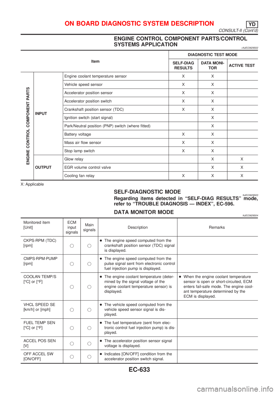
ENGINE CONTROL COMPONENT PARTS/CONTROL
SYSTEMS APPLICATION
=NJEC0629S02
ItemDIAGNOSTIC TEST MODE
SELF-DIAG
RESULTSDATA MONI-
TORACTIVE TEST
ENGINE CONTROL COMPONENT PARTS
INPUTEngine coolant temperature sensor X X
Vehicle speed sensor X X
Accelerator position sensor X X
Accelerator position switch X X
Crankshaft position sensor (TDC) X X
Ignition switch (start signal) X
Park/Neutral position (PNP) switch (where fitted) X
Battery voltage X X
Mass air flow sensor X X
Stop lamp switch X X
OUTPUTGlow relayXX
EGR volume control valve X X
Cooling fan relay X X X
X: Applicable
SELF-DIAGNOSTIC MODENJEC0629S03Regarding items detected in ªSELF-DIAG RESULTSº mode,
refer to ªTROUBLE DIAGNOSIS Ð INDEXº, EC-596.
DATA MONITOR MODENJEC0629S04
Monitored item
[Unit]ECM
input
signalsMain
signalsDescription Remarks
CKPS´RPM (TDC)
[rpm]jj+The engine speed computed from the
crankshaft position sensor (TDC) signal
is displayed.
CMPS´RPM´PUMP
[rpm]jj+The engine speed computed from the
pulse signal sent from electronic control
fuel injection pump is displayed.
COOLAN TEMP/S
[ÉC] or [ÉF]
jj+The engine coolant temperature (deter-
mined by the signal voltage of the
engine coolant temperature sensor) is
displayed.+When the engine coolant temperature
sensor is open or short-circuited, ECM
enters fail-safe mode. The engine cool-
ant temperature determined by the
ECM is displayed.
VHCL SPEED SE
[km/h] or [mph]jj+The vehicle speed computed from the
vehicle speed sensor signal is dis-
played.
FUEL TEMP SEN
[ÉC] or [ÉF]jj+The fuel temperature (sent from elec-
tronic control fuel injection pump) is dis-
played.
ACCEL POS SEN
[V]jj+The accelerator position sensor signal
voltage is displayed.
OFF ACCEL SW
[ON/OFF]jj+Indicates [ON/OFF] condition from the
accelerator position switch signal.
ON BOARD DIAGNOSTIC SYSTEM DESCRIPTIONYD
CONSULT-II (Cont'd)
EC-633
Page 1358 of 2898
![NISSAN ALMERA 2001 Service Manual Monitored item
[Unit]ECM
input
signalsMain
signalsDescription Remarks
SPILL/V [ÉCA]
j+The control position of spill valve (sent
from electronic control fuel injection
pump) is displayed.
BATTERY VOLT NISSAN ALMERA 2001 Service Manual Monitored item
[Unit]ECM
input
signalsMain
signalsDescription Remarks
SPILL/V [ÉCA]
j+The control position of spill valve (sent
from electronic control fuel injection
pump) is displayed.
BATTERY VOLT](/manual-img/5/57348/w960_57348-1357.png)
Monitored item
[Unit]ECM
input
signalsMain
signalsDescription Remarks
SPILL/V [ÉCA]
j+The control position of spill valve (sent
from electronic control fuel injection
pump) is displayed.
BATTERY VOLT [V]
jj+The power supply voltage of ECM is
displayed.
P/N POSI SW*1
[ON/OFF] (where
fitted)jj+Indicates [ON/OFF] condition from the
park/neutral position switch signal.
START SIGNAL
[ON/OFF]jj+Indicates [ON/OFF] condition from the
starter signal.+After starting the engine, [OFF] is dis-
played regardless of the starter signal.
BRAKE SW
[ON/OFF]jj+Indicates [ON/OFF] condition from the
stop lamp switch signal.
BRAKE SW2
[ON/OFF]jj+Indicates [ON/OFF] condition from the
brake pedal position switch signal.
IGN SW
[ON/OFF]jj+Indicates [ON/OFF] condition from igni-
tion switch signal.
MAS AIR/FL SE [V]
jj+The signal voltage of the mass air flow
sensor is displayed.+When the engine is stopped, a certain
value is indicated.
INT/A VOLUME [mg/]+The intake air volume computed from
the mass air flow sensor signal is dis-
played.
F/CUT SIGNAL
[ON/OFF]
j+The [ON/OFF] condition from decelera-
tion fuel cut signal (sent from electronic
control fuel injection pump) is displayed.
OFF´´´Fuel is cut off.
ON´´´Fuel is not cut off.
GLOW RLY
[ON/OFF]j+The glow relay control condition (deter-
mined by ECM according to the input
signal) is displayed.
COOLING FAN
[LOW/HI/OFF]
j+Indicates the control condition of the
cooling fans (determined by ECM
according to the input signal).
+LOW ... Operates at low speed.
HI ... Operates at high speed.
OFF ... Stopped.
BARO SEN [kPa]
jj+The barometric pressure (determined
by the signal voltage from the baromet-
ric pressure sensor built into the ECM)
is displayed.
EGR VOL CON/V
[step]
j+Indicates the EGR volume control value
computed by the ECM according to the
input signals.
+The opening becomes larger as the
value increases.
*1: On models not equipped with park/neutral position (PNP) switch, ªOFFº is always displayed regardless of gear shift position.
NOTE:
Any monitored item that does not match the vehicle being diagnosed is deleted from the display automatically.
ON BOARD DIAGNOSTIC SYSTEM DESCRIPTIONYD
CONSULT-II (Cont'd)
EC-634
Page 1359 of 2898
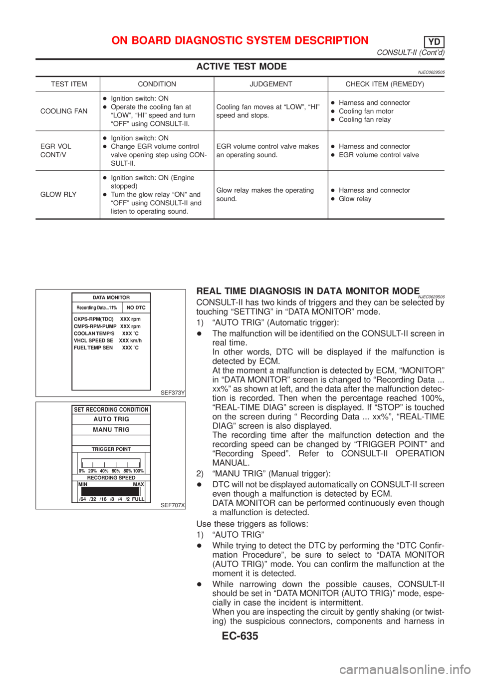
ACTIVE TEST MODENJEC0629S05
TEST ITEM CONDITION JUDGEMENT CHECK ITEM (REMEDY)
COOLING FAN+Ignition switch: ON
+Operate the cooling fan at
ªLOWº, ªHIº speed and turn
ªOFFº using CONSULT-II.Cooling fan moves at ªLOWº, ªHIº
speed and stops.+Harness and connector
+Cooling fan motor
+Cooling fan relay
EGR VOL
CONT/V+Ignition switch: ON
+Change EGR volume control
valve opening step using CON-
SULT-II.EGR volume control valve makes
an operating sound.+Harness and connector
+EGR volume control valve
GLOW RLY+Ignition switch: ON (Engine
stopped)
+Turn the glow relay ªONº and
ªOFFº using CONSULT-II and
listen to operating sound.Glow relay makes the operating
sound.+Harness and connector
+Glow relay
SEF373Y
SEF707X
REAL TIME DIAGNOSIS IN DATA MONITOR MODENJEC0629S06CONSULT-II has two kinds of triggers and they can be selected by
touching ªSETTINGº in ªDATA MONITORº mode.
1) ªAUTO TRIGº (Automatic trigger):
+The malfunction will be identified on the CONSULT-II screen in
real time.
In other words, DTC will be displayed if the malfunction is
detected by ECM.
At the moment a malfunction is detected by ECM, ªMONITORº
in ªDATA MONITORº screen is changed to ªRecording Data ...
xx%º as shown at left, and the data after the malfunction detec-
tion is recorded. Then when the percentage reached 100%,
ªREAL-TIME DIAGº screen is displayed. If ªSTOPº is touched
on the screen during ª Recording Data ... xx%º, ªREAL-TIME
DIAGº screen is also displayed.
The recording time after the malfunction detection and the
recording speed can be changed by ªTRIGGER POINTº and
ªRecording Speedº. Refer to CONSULT-II OPERATION
MANUAL.
2) ªMANU TRIGº (Manual trigger):
+DTC will not be displayed automatically on CONSULT-II screen
even though a malfunction is detected by ECM.
DATA MONITOR can be performed continuously even though
a malfunction is detected.
Use these triggers as follows:
1) ªAUTO TRIGº
+While trying to detect the DTC by performing the ªDTC Confir-
mation Procedureº, be sure to select to ªDATA MONITOR
(AUTO TRIG)º mode. You can confirm the malfunction at the
moment it is detected.
+While narrowing down the possible causes, CONSULT-II
should be set in ªDATA MONITOR (AUTO TRIG)º mode, espe-
cially in case the incident is intermittent.
When you are inspecting the circuit by gently shaking (or twist-
ing) the suspicious connectors, components and harness in
ON BOARD DIAGNOSTIC SYSTEM DESCRIPTIONYD
CONSULT-II (Cont'd)
EC-635
Page 1380 of 2898
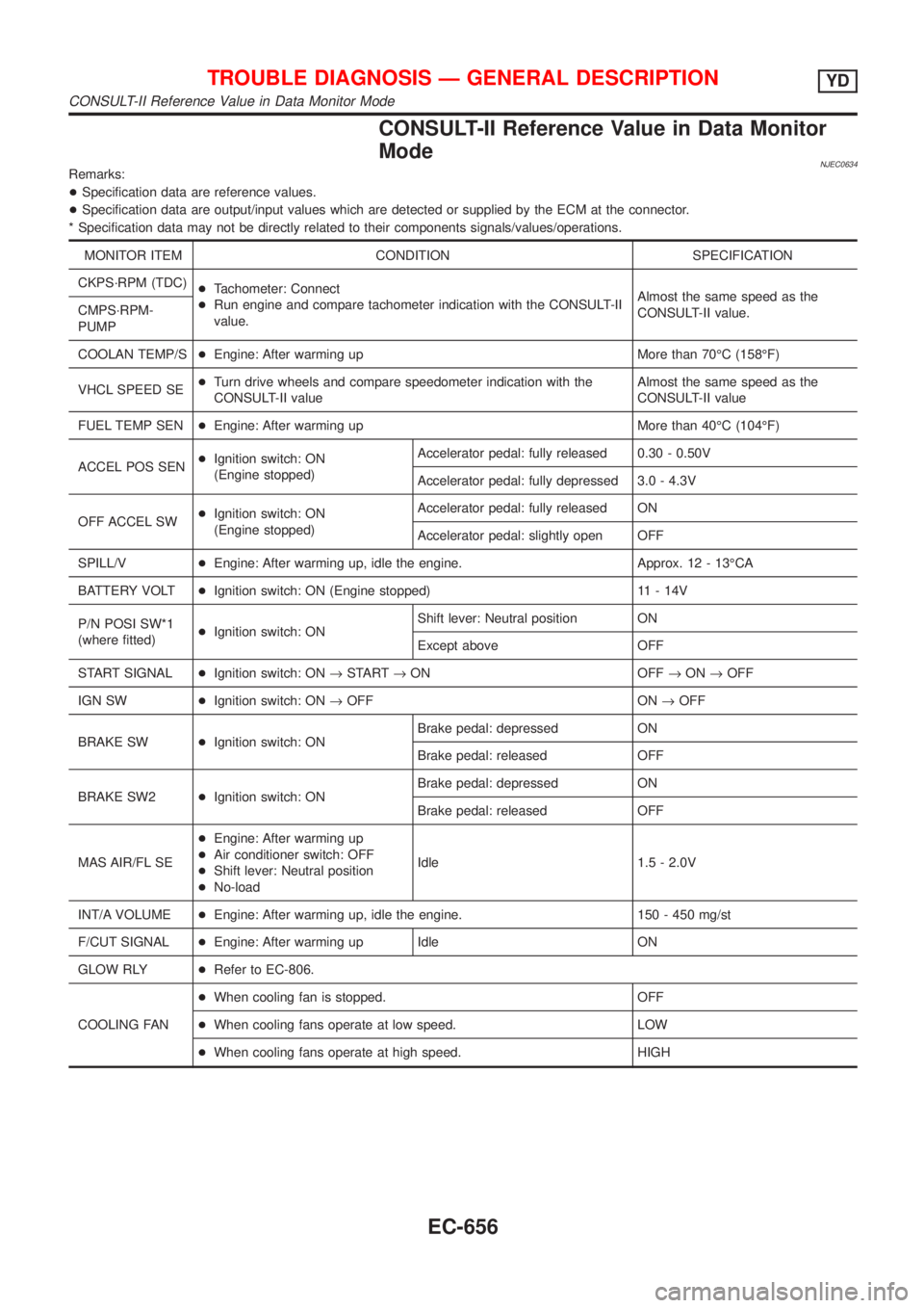
CONSULT-II Reference Value in Data Monitor
Mode
NJEC0634Remarks:
+Specification data are reference values.
+Specification data are output/input values which are detected or supplied by the ECM at the connector.
* Specification data may not be directly related to their components signals/values/operations.
MONITOR ITEM CONDITION SPECIFICATION
CKPS´RPM (TDC)
+Tachometer: Connect
+Run engine and compare tachometer indication with the CONSULT-II
value.Almost the same speed as the
CONSULT-II value. CMPS´RPM-
PUMP
COOLAN TEMP/S+Engine: After warming up More than 70ÉC (158ÉF)
VHCL SPEED SE+Turn drive wheels and compare speedometer indication with the
CONSULT-II valueAlmost the same speed as the
CONSULT-II value
FUEL TEMP SEN+Engine: After warming up More than 40ÉC (104ÉF)
ACCEL POS SEN+Ignition switch: ON
(Engine stopped)Accelerator pedal: fully released 0.30 - 0.50V
Accelerator pedal: fully depressed 3.0 - 4.3V
OFF ACCEL SW+Ignition switch: ON
(Engine stopped)Accelerator pedal: fully released ON
Accelerator pedal: slightly open OFF
SPILL/V+Engine: After warming up, idle the engine. Approx. 12 - 13ÉCA
BATTERY VOLT+Ignition switch: ON (Engine stopped) 11 - 14V
P/N POSI SW*1
(where fitted)+Ignition switch: ONShift lever: Neutral position ON
Except above OFF
START SIGNAL+Ignition switch: ON®START®ON OFF®ON®OFF
IGN SW+Ignition switch: ON®OFF ON®OFF
BRAKE SW+Ignition switch: ONBrake pedal: depressed ON
Brake pedal: released OFF
BRAKE SW2+Ignition switch: ONBrake pedal: depressed ON
Brake pedal: released OFF
MAS AIR/FL SE+Engine: After warming up
+Air conditioner switch: OFF
+Shift lever: Neutral position
+No-loadIdle 1.5 - 2.0V
INT/A VOLUME+Engine: After warming up, idle the engine. 150 - 450 mg/st
F/CUT SIGNAL+Engine: After warming up Idle ON
GLOW RLY+Refer to EC-806.
COOLING FAN+When cooling fan is stopped. OFF
+When cooling fans operate at low speed. LOW
+When cooling fans operate at high speed. HIGH
TROUBLE DIAGNOSIS Ð GENERAL DESCRIPTIONYD
CONSULT-II Reference Value in Data Monitor Mode
EC-656
Page 1385 of 2898
![NISSAN ALMERA 2001 Service Manual TERMI-
NAL
NO.WIRE
COLORITEM CONDITIONDATA (DC Voltage and Pulse
Signal)
104
105
106B
B
BECM ground[Engine is running]
+Idle speedApproximately 0V
107
108
109R
R
RPower supply for ECM[Ignition switch NISSAN ALMERA 2001 Service Manual TERMI-
NAL
NO.WIRE
COLORITEM CONDITIONDATA (DC Voltage and Pulse
Signal)
104
105
106B
B
BECM ground[Engine is running]
+Idle speedApproximately 0V
107
108
109R
R
RPower supply for ECM[Ignition switch](/manual-img/5/57348/w960_57348-1384.png)
TERMI-
NAL
NO.WIRE
COLORITEM CONDITIONDATA (DC Voltage and Pulse
Signal)
104
105
106B
B
BECM ground[Engine is running]
+Idle speedApproximately 0V
107
108
109R
R
RPower supply for ECM[Ignition switch ªONº]BATTERY VOLTAGE
(11 - 14V)
204 L Air conditioner relay[Engine is running]
+Air conditioner switch is ªOFFºBATTERY VOLTAGE
(11 - 14V)
[Engine is running]
+Both air conditioner switch and blower fan
switch are ªONº
(Compressor is operating)Approximately 0.1V
214 W/B Glow relay Refer to ªGlow Control Systemº, EC-806.
218 B Sensors' ground[Engine is running]
+Warm-up condition
+Idle speedApproximately 0V
219 LG/R Cooling fan relay (Low)[Engine is running]
+Cooling fan is not operatingBATTERY VOLTAGE
(11 - 14V)
[Engine is running]
+Cooling fan is operatingApproximately 0.1V
221 LG/B Cooling fan relay (High)[Engine is running]
+Cooling fan is not operating
+Cooling fan is operating at low speedBATTERY VOLTAGE
(11 - 14V)
[Engine is running]
+Cooling fan is operating at high speedApproximately 0.1V
223 WMass air flow sensor
power supply[Ignition switch ªONº]Approximately 5V
224 R Mass air flow sensor[Engine is running]
+Warm-up condition
+Idle speed1.5 - 2.0V
313 L/WElectronic control fuel
injection pump[Engine is running]
+Warm-up condition
+Idle speedApproximately 0.1V
314 L/RElectronic control fuel
injection pump[Engine is running]
+Warm-up condition
+Idle speedApproximately 0.4V
316 PUElectronic control fuel
injection pump[Engine is running]
+Warm-up condition
+Idle speedApproximately 2.5V
317 PElectronic control fuel
injection pump[Engine is running]
+Warm-up condition
+Idle speedApproximately 2.5V
325 G ECM relay (Self-shutoff)[Ignition switch ªONº]
[Ignition switch ªOFFº]
+For a few seconds after turning ignition switch
ªOFFºApproximately 0.25V
[Ignition switch ªOFFº]
+A few seconds passed after turning ignition
switch ªOFFºBATTERY VOLTAGE
(11 - 14V)
TROUBLE DIAGNOSIS Ð GENERAL DESCRIPTIONYD
ECM Terminals and Reference Value (Cont'd)
EC-661
Page 1454 of 2898
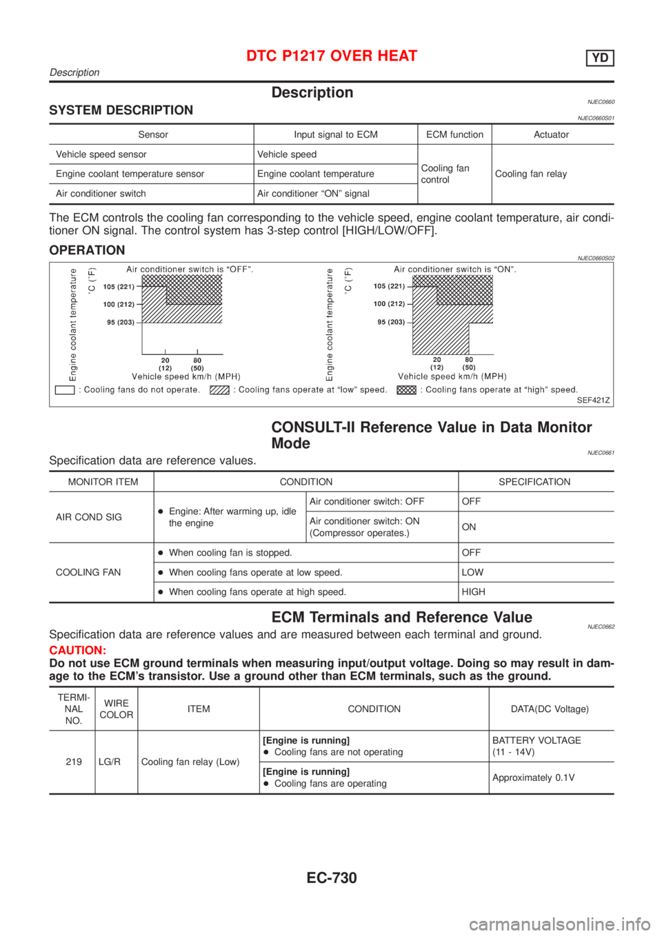
DescriptionNJEC0660SYSTEM DESCRIPTIONNJEC0660S01
Sensor Input signal to ECM ECM function Actuator
Vehicle speed sensor Vehicle speed
Cooling fan
controlCooling fan relay Engine coolant temperature sensor Engine coolant temperature
Air conditioner switch Air conditioner ªONº signal
The ECM controls the cooling fan corresponding to the vehicle speed, engine coolant temperature, air condi-
tioner ON signal. The control system has 3-step control [HIGH/LOW/OFF].
OPERATIONNJEC0660S02
SEF421Z
CONSULT-II Reference Value in Data Monitor
Mode
NJEC0661Specification data are reference values.
MONITOR ITEM CONDITION SPECIFICATION
AIR COND SIG+Engine: After warming up, idle
the engineAir conditioner switch: OFF OFF
Air conditioner switch: ON
(Compressor operates.)ON
COOLING FAN+When cooling fan is stopped. OFF
+When cooling fans operate at low speed. LOW
+When cooling fans operate at high speed. HIGH
ECM Terminals and Reference ValueNJEC0662Specification data are reference values and are measured between each terminal and ground.
CAUTION:
Do not use ECM ground terminals when measuring input/output voltage. Doing so may result in dam-
age to the ECM's transistor. Use a ground other than ECM terminals, such as the ground.
TERMI-
NAL
NO.WIRE
COLORITEM CONDITION DATA(DC Voltage)
219 LG/R Cooling fan relay (Low)[Engine is running]
+Cooling fans are not operatingBATTERY VOLTAGE
(11 - 14V)
[Engine is running]
+Cooling fans are operatingApproximately 0.1V
DTC P1217 OVER HEATYD
Description
EC-730
Page 1455 of 2898
![NISSAN ALMERA 2001 Service Manual TERMI-
NAL
NO.WIRE
COLORITEM CONDITION DATA(DC Voltage)
221 LG/B Cooling fan relay (High)[Engine is running]
+Cooling fans are not operating
+Cooling fans are operating at low speedBATTERY VOLTAGE
(11 NISSAN ALMERA 2001 Service Manual TERMI-
NAL
NO.WIRE
COLORITEM CONDITION DATA(DC Voltage)
221 LG/B Cooling fan relay (High)[Engine is running]
+Cooling fans are not operating
+Cooling fans are operating at low speedBATTERY VOLTAGE
(11](/manual-img/5/57348/w960_57348-1454.png)
TERMI-
NAL
NO.WIRE
COLORITEM CONDITION DATA(DC Voltage)
221 LG/B Cooling fan relay (High)[Engine is running]
+Cooling fans are not operating
+Cooling fans are operating at low speedBATTERY VOLTAGE
(11 - 14V)
[Engine is running]
+Cooling fans are operating at high speedApproximately 0.1V
On Board Diagnosis LogicNJEC0663This diagnosis continuously monitors the engine coolant temperature.
If the cooling fan or another component in the cooling system malfunctions, engine coolant temperature will
rise.
When the engine coolant temperature reaches an abnormally high temperature condition, a malfunction is
indicated.
DTC Malfunction is detected when ... Check Items (Possible Cause)
P1217
0208+Cooling fan does not operate properly (Overheat).
+Cooling fan system does not operate properly
(Overheat).
+Engine coolant was not added to the system using
the proper filling method.+Harness or connectors
(The cooling fan circuit is open or shorted.)
+Cooling fan
+Radiator hose
+Radiator
+Radiator cap
+Water pump
+Thermostat
+Engine coolant temperature sensor
For more information, refer to ªMAIN 12 CAUSES OF
OVERHEATINGº, EC-756.
CAUTION:
When a malfunction is indicated, be sure to replace the coolant following the procedure in the LC-44,
ªChanging Engine Coolantº. Also, replace the engine oil.
1) Fill radiator with coolant up to specified level with a filling speed of 2 liters per minute. Be sure
to use coolant with the proper mixture ratio. Refer to MA-18, ªEngine Coolant Mixture Ratioº.
2) After refilling coolant, run engine to ensure that no water-flow noise is emitted.
DTC P1217 OVER HEATYD
ECM Terminals and Reference Value (Cont'd)
EC-731
Page 1456 of 2898
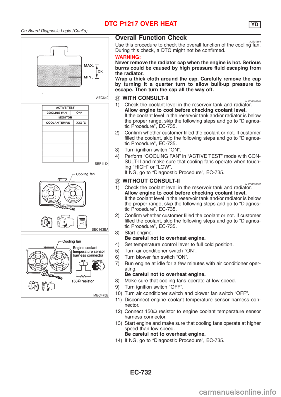
AEC640
SEF111X
SEC163BA
MEC475B
Overall Function CheckNJEC0664Use this procedure to check the overall function of the cooling fan.
During this check, a DTC might not be confirmed.
WARNING:
Never remove the radiator cap when the engine is hot. Serious
burns could be caused by high pressure fluid escaping from
the radiator.
Wrap a thick cloth around the cap. Carefully remove the cap
by turning it a quarter turn to allow built-up pressure to
escape. Then turn the cap all the way off.
WITH CONSULT-IINJEC0664S011) Check the coolant level in the reservoir tank and radiator.
Allow engine to cool before checking coolant level.
If the coolant level in the reservoir tank and/or radiator is below
the proper range, skip the following steps and go to ªDiagnos-
tic Procedureº, EC-735.
2) Confirm whether customer filled the coolant or not. If customer
filled the coolant, skip the following steps and go to ªDiagnos-
tic Procedureº, EC-735.
3) Turn ignition switch ªONº.
4) Perform ªCOOLING FANº in ªACTIVE TESTº mode with CON-
SULT-II and make sure that cooling fans operate when touch-
ing ªHIGHº or ªLOWº.
If NG, go to ªDiagnostic Procedureº, EC-735.
WITHOUT CONSULT-IINJEC0664S021) Check the coolant level in the reservoir tank and radiator.
Allow engine to cool before checking coolant level.
If the coolant level in the reservoir tank and/or radiator is below
the proper range, skip the following steps and go to ªDiagnos-
tic Procedureº, EC-735.
2) Confirm whether customer filled the coolant or not. If customer
filled the coolant, skip the following steps and go to ªDiagnos-
tic Procedureº, EC-735.
3) Start engine.
Be careful not to overheat engine.
4) Set temperature control lever to full cold position.
5) Turn air conditioner switch ªONº.
6) Turn blower fan switch ªONº.
7) Run engine at idle for a few minutes with air conditioner oper-
ating.
Be careful not to overheat engine.
8) Make sure that cooling fans operate at low speed.
9) Turn ignition switch ªOFFº.
10) Turn air conditioner switch and blower fan switch ªOFFº.
11) Disconnect engine coolant temperature sensor harness con-
nector.
12) Connect 150Wresistor to engine coolant temperature sensor
harness connector.
13) Start engine and make sure that cooling fans operate at higher
speed than low speed.
Be careful not to overheat engine.
14) If NG, go to ªDiagnostic Procedureº, EC-735.
DTC P1217 OVER HEATYD
On Board Diagnosis Logic (Cont'd)
EC-732