2001 NISSAN ALMERA cooling
[x] Cancel search: coolingPage 2272 of 2898
crankshaft position sensor (TDC sensor) from the assem-
bly.
+Always pay extra attention not to damage edge of crank-
shaft position sensor (TDC sensor) or ring gear teeth.
REMOVALNJEM0069S011. Remove engine undercover, and hood for hoisting.
2. Drain coolant from both cylinder block and radiator. Refer to
LC-44, ªChanging Engine Coolantº.
3. Remove the following parts:
+Battery
+RH and LH front wheels
+RH and LH splash covers (combined with undercover)
+Auxiliary belts
+Alternator
+Alternator brackets
+Radiator and cooling fan
+Engine cover
+Air ducts and air cleaner case
LH side of engine room:
4. Disconnect all harnesses and grounds that are connected to
components on vehicle.
5. Disconnect vacuum hose on vacuum pump side.
6. Disconnect fuel feed and fuel return hoses on engine side.
+Immediately put blind plugs into the openings to prevent
fuel from flowing out.
7. Disconnect heater hose. Plug opening of hose to prevent cool-
ant from flowing out.
RH side of engine room:
8. Remove air conditioner compressor from brackets and move
it toward vehicle side. Secure compressor on vehicle side with
rope.
Vehicle underside:
9. Remove exhaust front tube.
10. Disconnect two hoses from power steering pump and plug to
stop fluid.
11. Remove M/T control rod and support rod.
12. Remove ABS wheel sensor, and temporarily hang brake cali-
per with rope on vehicle side.
13. Remove RH and LH drive shafts.
SEM666G
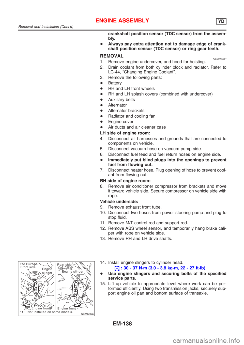
14. Install engine slingers to cylinder head.
: 30 - 37 N´m (3.0 - 3.8 kg-m, 22 - 27 ft-lb)
+Use engine slingers and securing bolts of the specified
service parts.
15. Lift up vehicle to appropriate level where work can be per-
formed efficiently. Using two transmission jacks, securely sup-
port engine oil pan and bottom surface of transaxle.
ENGINE ASSEMBLYYD
Removal and Installation (Cont'd)
EM-138
Page 2401 of 2898
HEATER &
AIR CONDITIONER
SECTION
HA
CONTENTS
PRECAUTIONS...............................................................2
Supplemental Restraint System (SRS)²AIR
BAG²and²SEAT BELT PRE-TENSIONER²...............2
Precautions for Working with HFC-134a (R-134a) .....2
General Refrigerant Precautions .................................2
Precautions for Refrigerant Connection ......................3
Precautions for Servicing Compressor ........................5
Precautions for Service Equipment .............................6
Wiring Diagrams and Trouble Diagnosis .....................8
PREPARATION...............................................................9
Special Service Tools ..................................................9
HFC-134a (R-134a) Service Tools and
Equipment .................................................................. 11
DESCRIPTION...............................................................13
Refrigeration System .................................................13
CSV613 Variable Displacement Compressor............14
Component Layout ....................................................18
Control Operation ......................................................19
Discharge Air Flow.....................................................20
System Description ....................................................21
TROUBLE DIAGNOSES................................................22
Component Location..................................................22
Wiring Diagram - Heater............................................24
Circuit Diagram - Air Conditioner...............................26
Wiring Diagram - A/C, M - .........................................27
How to Perform Trouble Diagnoses for Quick
and Accurate Repair ..................................................33
Operational Check .....................................................34
Intake Door ................................................................36
Mode Door .................................................................40Air Mix Door ...............................................................42
Max Hot Door (For Scandinavia and Cold Spec
Models) ......................................................................44
Blower Motor..............................................................48
Magnet Clutch............................................................55
Insufficient Cooling ....................................................68
Insufficient Heating ....................................................76
Noise ..........................................................................77
SERVICE PROCEDURE................................................78
HFC-134a (R-134a) Service Procedure ....................78
Maintenance of Lubricant Quantity in
Compressor ...............................................................80
Compressor ...............................................................83
Compressor Clutch - CSV613 (CALSONIC
make) .........................................................................84
Heater & Cooling Unit (Heater Core) ........................88
A/C Evaporator ..........................................................88
Blower Unit ................................................................89
Refrigerant Lines .......................................................91
Belt .............................................................................95
Idle Air Control Valve (IACV) - Auxiliary Air
Control (AAC) Valve ..................................................96
Ventilation Air Filter ....................................................96
SERVICE DATA AND SPECIFICATIONS (SDS).........97
Compressor ...............................................................97
Lubricant ....................................................................97
Refrigerant .................................................................97
Engine Idling Speed (When A/C is On).....................97
Belt Tension ...............................................................97
Page 2403 of 2898
+Do not store or heat refrigerant containers above 52ÉC (125ÉF).
+Do not heat a refrigerant container with an open flame; if container warming is required, place the
bottom of the container in a warm pail of water.
+Do not intentionally drop, puncture, or incinerate refrigerant containers.
+Keep refrigerant away from open flames: poisonous gas will be produced if refrigerant burns.
+Refrigerant will displace oxygen, therefore be certain to work in well ventilated areas to prevent
suffocation.
+Do not pressure test or leak test HFC-134a (R-134a) service equipment and/or vehicle air condi-
tioning systems with compressed air during repair. Some mixtures of air and R-134a have been
shown to be combustible at elevated pressures. These mixtures, if ignited, may cause injury or
property damage. Additional health and safety information may be obtained from refrigerant manu-
facturers.
Precautions for Refrigerant ConnectionNJHA0115A new type refrigerant connection has been introduced to all refrigerant lines except the following portion.
+Expansion valve to cooling unit
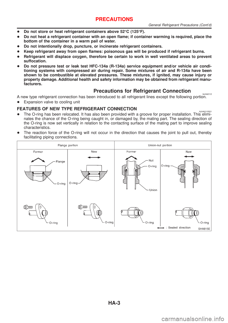
FEATURES OF NEW TYPE REFRIGERANT CONNECTIONNJHA0115S01+The O-ring has been relocated. It has also been provided with a groove for proper installation. This elimi-
nates the chance of the O-ring being caught in, or damaged by, the mating part. The sealing direction of
the O-ring is now set vertically in relation to the contacting surface of the mating part to improve sealing
characteristics.
+The reaction force of the O-ring will not occur in the direction that causes the joint to pull out, thereby
facilitating piping connections.
SHA815E
PRECAUTIONS
General Refrigerant Precautions (Cont'd)
HA-3
Page 2413 of 2898
Refrigeration System
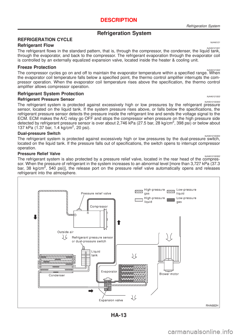
REFRIGERATION CYCLENJHA0121Refrigerant FlowNJHA0121S01The refrigerant flows in the standard pattern, that is, through the compressor, the condenser, the liquid tank,
through the evaporator, and back to the compressor. The refrigerant evaporation through the evaporator coil
is controlled by an externally equalized expansion valve, located inside the heater & cooling unit.
Freeze ProtectionNJHA0121S02The compressor cycles go on and off to maintain the evaporator temperature within a specified range. When
the evaporator coil temperature falls below a specified point, the thermo control amplifier interrupts the com-
pressor operation. When the evaporator coil temperature rises above the specification, the thermo control
amplifier allows compressor operation.
Refrigerant System ProtectionNJHA0121S03Refrigerant Pressure SensorNJHA0121S0303The refrigerant system is protected against excessively high or low pressures by the refrigerant pressure
sensor, located on the liquid tank. If the system pressure rises above, or falls below the specifications, the
refrigerant pressure sensor detects the pressure inside the refrigerant line and sends the voltage signal to the
ECM. ECM makes the A/C relay go OFF and stops the compressor when pressure on the high pressure side
detected by refrigerant pressure sensor is over about 2,746 kPa (27.5 bar, 28 kg/cm
2, 398 psi) or below about
137 kPa (1.37 bar, 1.4 kg/cm2, 20 psi).
Dual-pressure Switch
NJHA0121S0304The refrigerant system is protected against excessively high or low pressures by the dual-pressure switch,
located on the liquid tank. If the pressure falls out of specifications, the switch opens to interrupt compressor
operation.
Pressure Relief Valve
NJHA0121S0302The refrigerant system is also protected by a pressure relief valve, located in the rear head of the compres-
sor. When the pressure of refrigerant in the system increases to an abnormal level [more than 3,727 kPa (37.3
bar, 38 kg/cm
2, 540 psi)], the release port on the pressure relief valve automatically opens and releases
refrigerant into the atmosphere.
RHA682H
DESCRIPTION
Refrigeration System
HA-13
Page 2415 of 2898

DESCRIPTION=NJHA0207GeneralNJHA0207S01The variable compressor is basically a swash plate type that changes piston stroke in response to the required
cooling capacity.
The tilt of the swash plate allows the piston's stroke to change so that refrigerant discharge can be continu-
ously changed from 6.0 to 125 cm
3(0.366 to 7.628 cu in).
RHA854HA
DESCRIPTION
CSV613 Variable Displacement Compressor (Cont'd)
HA-15
Page 2416 of 2898
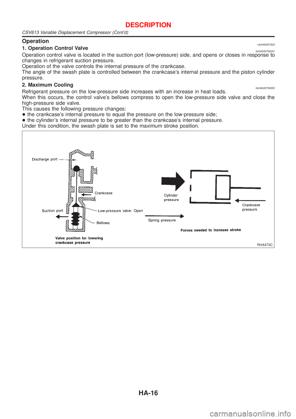
Operation=NJHA0207S021. Operation Control ValveNJHA0207S0201Operation control valve is located in the suction port (low-pressure) side, and opens or closes in response to
changes in refrigerant suction pressure.
Operation of the valve controls the internal pressure of the crankcase.
The angle of the swash plate is controlled between the crankcase's internal pressure and the piston cylinder
pressure.
2. Maximum Cooling
NJHA0207S0202Refrigerant pressure on the low-pressure side increases with an increase in heat loads.
When this occurs, the control valve's bellows compress to open the low-pressure side valve and close the
high-pressure side valve.
This causes the following pressure changes:
+the crankcase's internal pressure to equal the pressure on the low-pressure side;
+the cylinder's internal pressure to be greater than the crankcase's internal pressure.
Under this condition, the swash plate is set to the maximum stroke position.
RHA473C
DESCRIPTION
CSV613 Variable Displacement Compressor (Cont'd)
HA-16
Page 2419 of 2898
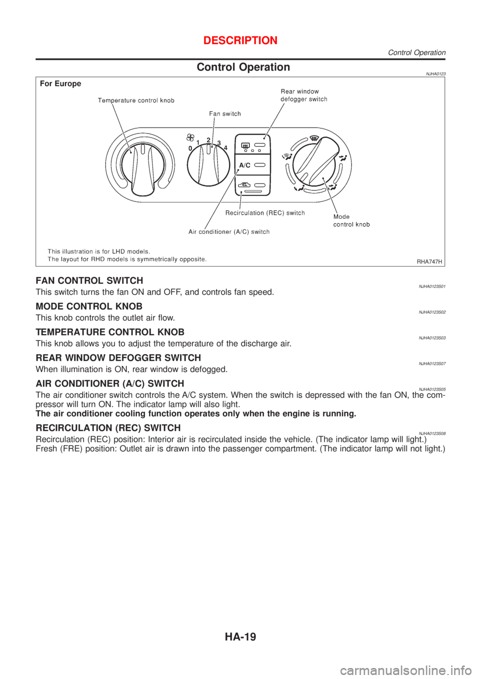
Control OperationNJHA0123
RHA747H
FAN CONTROL SWITCHNJHA0123S01This switch turns the fan ON and OFF, and controls fan speed.
MODE CONTROL KNOBNJHA0123S02This knob controls the outlet air flow.
TEMPERATURE CONTROL KNOBNJHA0123S03This knob allows you to adjust the temperature of the discharge air.
REAR WINDOW DEFOGGER SWITCHNJHA0123S07When illumination is ON, rear window is defogged.
AIR CONDITIONER (A/C) SWITCHNJHA0123S05The air conditioner switch controls the A/C system. When the switch is depressed with the fan ON, the com-
pressor will turn ON. The indicator lamp will also light.
The air conditioner cooling function operates only when the engine is running.
RECIRCULATION (REC) SWITCHNJHA0123S08Recirculation (REC) position: Interior air is recirculated inside the vehicle. (The indicator lamp will light.)
Fresh (FRE) position: Outlet air is drawn into the passenger compartment. (The indicator lamp will not light.)
DESCRIPTION
Control Operation
HA-19
Page 2433 of 2898
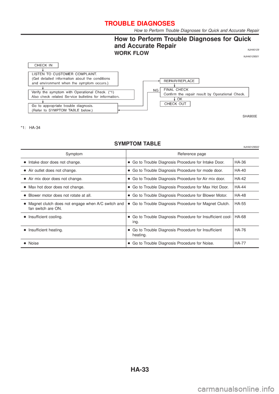
How to Perform Trouble Diagnoses for Quick
and Accurate Repair
NJHA0129WORK FLOWNJHA0129S01
SHA900E
*1: HA-34
SYMPTOM TABLENJHA0129S02
Symptom Reference page
+Intake door does not change.+Go to Trouble Diagnosis Procedure for Intake Door. HA-36
+Air outlet does not change.+Go to Trouble Diagnosis Procedure for mode door. HA-40
+Air mix door does not change.+Go to Trouble Diagnosis Procedure for Air mix door. HA-42
+Max hot door does not change.+Go to Trouble Diagnosis Procedure for Max Hot Door. HA-44
+Blower motor does not rotate at all.+Go to Trouble Diagnosis Procedure for Blower Motor. HA-48
+Magnet clutch does not engage when A/C switch and
fan switch are ON.+Go to Trouble Diagnosis Procedure for Magnet Clutch. HA-55
+Insufficient cooling.+Go to Trouble Diagnosis Procedure for Insufficient cool-
ing.HA-68
+Insufficient heating.+Go to Trouble Diagnosis Procedure for Insufficient
heating.HA-76
+Noise+Go to Trouble Diagnosis Procedure for Noise. HA-77
TROUBLE DIAGNOSES
How to Perform Trouble Diagnoses for Quick and Accurate Repair
HA-33