2001 NISSAN ALMERA steering
[x] Cancel search: steeringPage 1616 of 2898
CEL501
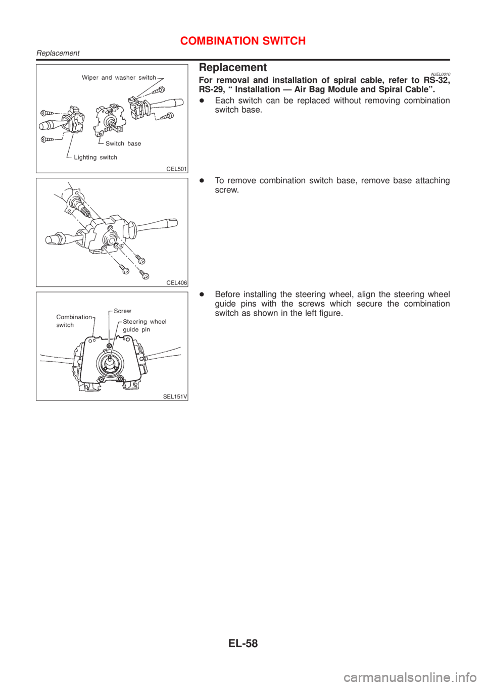
ReplacementNJEL0010For removal and installation of spiral cable, refer to RS-32,
RS-29, ª Installation Ð Air Bag Module and Spiral Cableº.
+Each switch can be replaced without removing combination
switch base.
CEL406
+To remove combination switch base, remove base attaching
screw.
SEL151V
+Before installing the steering wheel, align the steering wheel
guide pins with the screws which secure the combination
switch as shown in the left figure.
COMBINATION SWITCH
Replacement
EL-58
Page 1617 of 2898

CheckNJEL0350
NEL826
STEERING SWITCH
Check
EL-59
Page 2010 of 2898
SEL504X
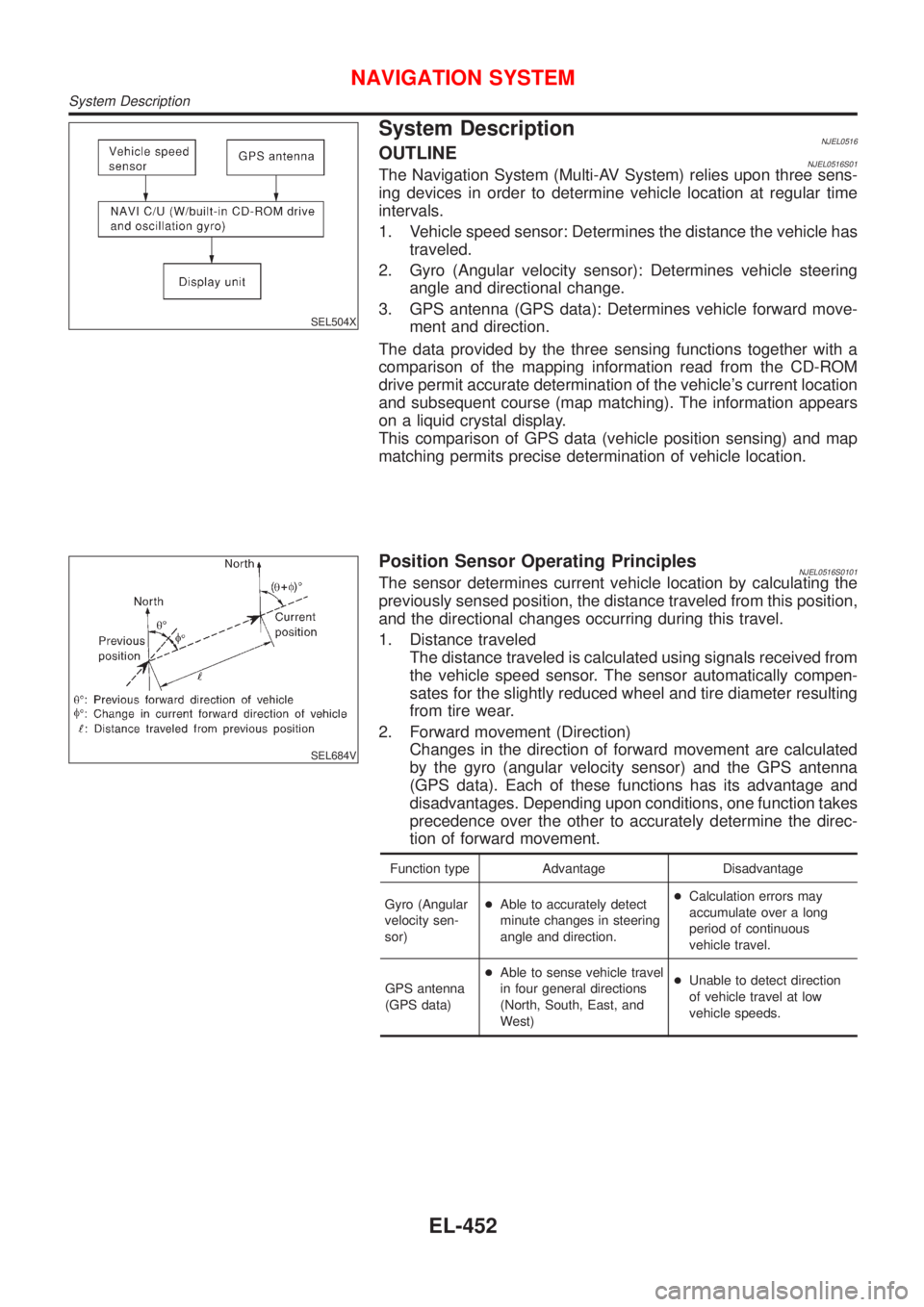
System DescriptionNJEL0516OUTLINENJEL0516S01The Navigation System (Multi-AV System) relies upon three sens-
ing devices in order to determine vehicle location at regular time
intervals.
1. Vehicle speed sensor: Determines the distance the vehicle has
traveled.
2. Gyro (Angular velocity sensor): Determines vehicle steering
angle and directional change.
3. GPS antenna (GPS data): Determines vehicle forward move-
ment and direction.
The data provided by the three sensing functions together with a
comparison of the mapping information read from the CD-ROM
drive permit accurate determination of the vehicle's current location
and subsequent course (map matching). The information appears
on a liquid crystal display.
This comparison of GPS data (vehicle position sensing) and map
matching permits precise determination of vehicle location.
SEL684V
Position Sensor Operating PrinciplesNJEL0516S0101The sensor determines current vehicle location by calculating the
previously sensed position, the distance traveled from this position,
and the directional changes occurring during this travel.
1. Distance traveled
The distance traveled is calculated using signals received from
the vehicle speed sensor. The sensor automatically compen-
sates for the slightly reduced wheel and tire diameter resulting
from tire wear.
2. Forward movement (Direction)
Changes in the direction of forward movement are calculated
by the gyro (angular velocity sensor) and the GPS antenna
(GPS data). Each of these functions has its advantage and
disadvantages. Depending upon conditions, one function takes
precedence over the other to accurately determine the direc-
tion of forward movement.
Function type Advantage Disadvantage
Gyro (Angular
velocity sen-
sor)+Able to accurately detect
minute changes in steering
angle and direction.+Calculation errors may
accumulate over a long
period of continuous
vehicle travel.
GPS antenna
(GPS data)+Able to sense vehicle travel
in four general directions
(North, South, East, and
West)+Unable to detect direction
of vehicle travel at low
vehicle speeds.
NAVIGATION SYSTEM
System Description
EL-452
Page 2011 of 2898
SEL685V
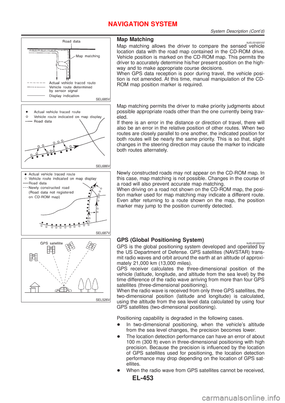
Map MatchingNJEL0516S0102Map matching allows the driver to compare the sensed vehicle
location data with the road map contained in the CD-ROM drive.
Vehicle position is marked on the CD-ROM map. This permits the
driver to accurately determine his/her present position on the high-
way and to make appropriate course decisions.
When GPS data reception is poor during travel, the vehicle posi-
tion is not amended. At this time, manual manipulation of the CD-
ROM map position marker is required.
SEL686V
Map matching permits the driver to make priority judgments about
possible appropriate roads other than the one currently being trav-
eled.
If there is an error in the distance or direction of travel, there will
also be an error in the relative position of other routes. When two
routes are closely parallel to one another, the indicated position for
both routes will be nearly the same priority. This is so that, slight
changes in the steering direction may cause the marker to indicate
both routes alternately.
SEL687V
Newly constructed roads may not appear on the CD-ROM map. In
this case, map matching is not possible. Changes in the course of
a road will also prevent accurate map matching.
When driving on a road not shown on the CD-ROM map, the posi-
tion marker used for map matching may indicate a different route.
Even after returning to a route shown on the map, the position
marker may jump to the position currently detected.
SEL526V
GPS (Global Positioning System)NJEL0516S0103GPS is the global positioning system developed and operated by
the US Department of Defense. GPS satellites (NAVSTAR) trans-
mit radio waves and orbit around the earth at an altitude of approxi-
mately 21,000 km (13,000 miles).
GPS receiver calculates the three-dimensional position of the
vehicle (latitude, longitude, and altitude from the sea level) by the
time difference of the radio wave arriving from more than four GPS
satellites (three-dimensional positioning).
When the radio wave is received from only three GPS satellites, the
two-dimensional position (latitude and longitude) is calculated,
using the altitude from the sea level data calculated by using four
GPS satellites (two-dimensional positioning).
Positioning capability is degraded in the following cases.
+In two-dimensional positioning, when the vehicle's altitude
from the sea level changes, the precision becomes lower.
+The location detection performance can have an error of about
100 m (300 ft) even in three-dimensional positioning with high
precision. Because the precision is influenced by the location
of GPS satellites used for positioning, the location detection
performance may drop depending on the location of GPS sat-
ellites.
+When the radio wave from GPS satellites cannot be received,
NAVIGATION SYSTEM
System Description (Cont'd)
EL-453
Page 2012 of 2898
for example, when the vehicle is in a tunnel, in a parking lot
inside building, under an elevated superhighway or near strong
power lines, the location may not be detected. Turbulent/
electric weather conditions may also affect positioning perfor-
mance. If something is placed on the antenna, the radio wave
from GPS satellites may not be received.
SEL507X
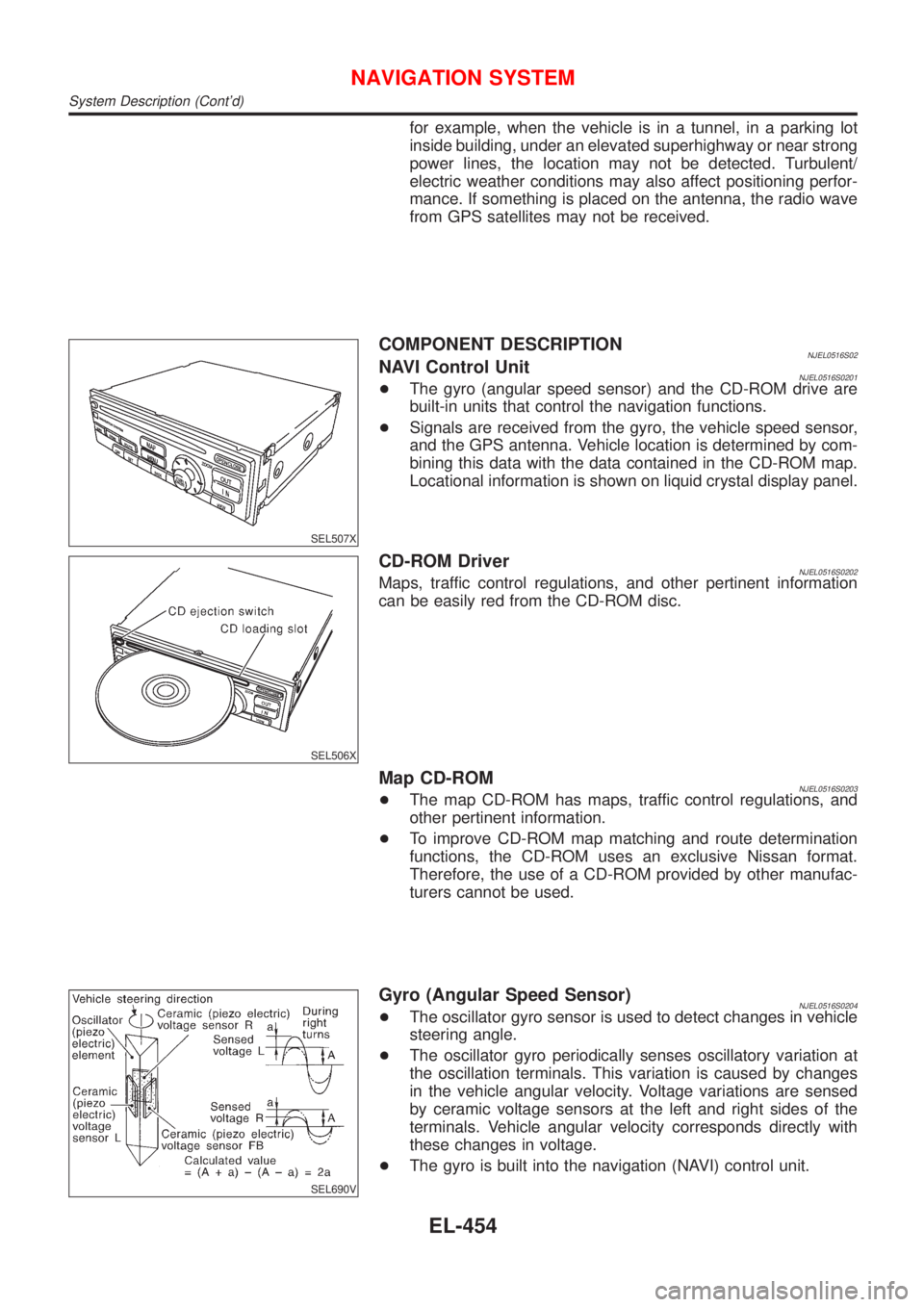
COMPONENT DESCRIPTIONNJEL0516S02NAVI Control UnitNJEL0516S0201+The gyro (angular speed sensor) and the CD-ROM drive are
built-in units that control the navigation functions.
+Signals are received from the gyro, the vehicle speed sensor,
and the GPS antenna. Vehicle location is determined by com-
bining this data with the data contained in the CD-ROM map.
Locational information is shown on liquid crystal display panel.
SEL506X
CD-ROM DriverNJEL0516S0202Maps, traffic control regulations, and other pertinent information
can be easily red from the CD-ROM disc.
Map CD-ROMNJEL0516S0203+The map CD-ROM has maps, traffic control regulations, and
other pertinent information.
+To improve CD-ROM map matching and route determination
functions, the CD-ROM uses an exclusive Nissan format.
Therefore, the use of a CD-ROM provided by other manufac-
turers cannot be used.
SEL690V
Gyro (Angular Speed Sensor)NJEL0516S0204+The oscillator gyro sensor is used to detect changes in vehicle
steering angle.
+The oscillator gyro periodically senses oscillatory variation at
the oscillation terminals. This variation is caused by changes
in the vehicle angular velocity. Voltage variations are sensed
by ceramic voltage sensors at the left and right sides of the
terminals. Vehicle angular velocity corresponds directly with
these changes in voltage.
+The gyro is built into the navigation (NAVI) control unit.
NAVIGATION SYSTEM
System Description (Cont'd)
EL-454
Page 2065 of 2898
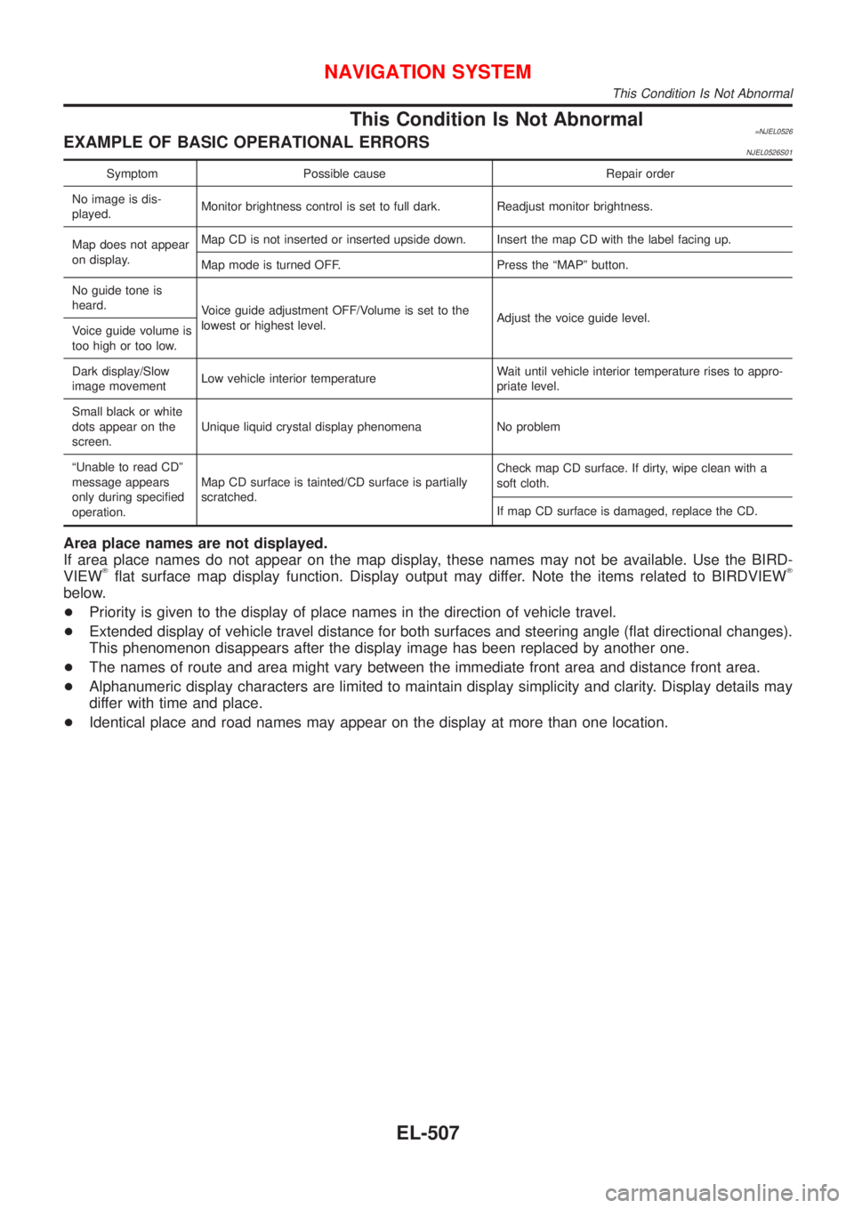
This Condition Is Not Abnormal=NJEL0526EXAMPLE OF BASIC OPERATIONAL ERRORSNJEL0526S01
Symptom Possible cause Repair order
No image is dis-
played.Monitor brightness control is set to full dark. Readjust monitor brightness.
Map does not appear
on display.Map CD is not inserted or inserted upside down. Insert the map CD with the label facing up.
Map mode is turned OFF. Press the ªMAPº button.
No guide tone is
heard.
Voice guide adjustment OFF/Volume is set to the
lowest or highest level.Adjust the voice guide level.
Voice guide volume is
too high or too low.
Dark display/Slow
image movementLow vehicle interior temperatureWait until vehicle interior temperature rises to appro-
priate level.
Small black or white
dots appear on the
screen.Unique liquid crystal display phenomena No problem
ªUnable to read CDº
message appears
only during specified
operation.Map CD surface is tainted/CD surface is partially
scratched.Check map CD surface. If dirty, wipe clean with a
soft cloth.
If map CD surface is damaged, replace the CD.
Area place names are not displayed.
If area place names do not appear on the map display, these names may not be available. Use the BIRD-
VIEW
Tflat surface map display function. Display output may differ. Note the items related to BIRDVIEWT
below.
+Priority is given to the display of place names in the direction of vehicle travel.
+Extended display of vehicle travel distance for both surfaces and steering angle (flat directional changes).
This phenomenon disappears after the display image has been replaced by another one.
+The names of route and area might vary between the immediate front area and distance front area.
+Alphanumeric display characters are limited to maintain display simplicity and clarity. Display details may
differ with time and place.
+Identical place and road names may appear on the display at more than one location.
NAVIGATION SYSTEM
This Condition Is Not Abnormal
EL-507
Page 2066 of 2898

EXAMPLE OF CURRENT VEHICLE POSITION MARKER ERROR=NJEL0526S02The navigation system reads the vehicle distance and steering angle data. Because the vehicle is moving,
there will be an error in the current position indication. After the error appears, drive the vehicle for a short
distance. Stop the vehicle. If the position marker does not return to its original position, perform ªAdjust Cur-
rent Locationº MODE (EL-496).
SEL698V
NAVIGATION SYSTEM
This Condition Is Not Abnormal (Cont'd)
EL-508
Page 2067 of 2898
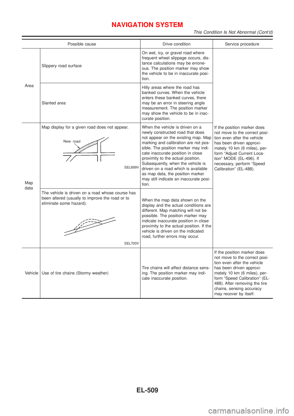
Possible cause Drive condition Service procedure
AreaSlippery road surfaceOn wet, icy, or gravel road where
frequent wheel slippage occurs, dis-
tance calculations may be errone-
ous. The position marker may show
the vehicle to be in inaccurate posi-
tion.
If the position marker does
not move to the correct posi-
tion even after the vehicle
has been driven approxi-
mately 10 km (6 miles), per-
form ªAdjust Current Loca-
tionº MODE (EL-496). If
necessary, perform ªSpeed
Calibrationº (EL-488). Slanted areaHilly areas where the road has
banked curves. When the vehicle
enters these banked curves, there
may be an error in steering angle
measurement. The position marker
may show the vehicle to be in inac-
curate position.
Map
dataMap display for a given road does not appear.
SEL699V
When the vehicle is driven on a
newly constructed road that does
not appear on the existing map. Map
marking and calibration are not pos-
sible. The position marker may indi-
cate inaccurate position in close
proximity to the actual position.
Subsequently, when the vehicle is
driven on a road which is available
as map data, the position marker
may still indicate an inaccurate posi-
tion.
The vehicle is driven on a road whose course has
been altered (usually to improve the road or to
eliminate some hazard).
SEL700V
When the map data shown on the
display and the actual conditions are
different. Map matching will not be
possible. The position marker may
indicate inaccurate position in close
proximity to the actual position. If the
vehicle is driven on the indicated
road, further errors may occur.
Vehicle Use of tire chains (Stormy weather)Tire chains will affect distance sens-
ing. The position marker may indi-
cate inaccurate position.If the position marker does
not move to the correct posi-
tion even after the vehicle
has been driven approxi-
mately 10 km (6 miles), per-
form ªSpeed Calibrationº (EL-
488). After removing the tire
chains, sensing accuracy
may recover by itself.
NAVIGATION SYSTEM
This Condition Is Not Abnormal (Cont'd)
EL-509