Page 2877 of 2898
ComponentsNJSU0005
NAX011
1. Front suspension member
2. Stabilizer bar
3. Transverse link4. Member pin stay
5. Knuckle
6. Strut assembly7. Coil spring
8. Washer
FRONT SUSPENSION
Components
SU-5
Page 2878 of 2898

SMA525A
On-vehicle Service
FRONT SUSPENSION PARTSNJSU0006Check front axle and front suspension parts for excessive play,
cracks, wear or other damage.
+Shake each front wheel to check for excessive play.
+Make sure that cotter pin is inserted.
+Retighten all axle and suspension nuts and bolts to the speci-
fied torque.
Tightening torque:
Refer to ªFRONT SUSPENSIONº, SU-5.
SFA392B
+Check strut (shock absorber) for oil leakage or other damage.
+Check suspension ball joint for grease leakage and ball joint
dust cover for cracks or other damage.
If ball joint dust cover is cracked or damaged, replace trans-
verse link.
SFA818AA
+Check spring height from top of wheelarch to the ground.
a) Vehicle must be unladen*, parked on a level surface, and tires
checked for proper inflation and wear (tread wear indicator
must not be showing).
*: Fuel, radiator coolant and engine oil full. Spare tire, jack,
hand tools and mats in designated positions.
b) Bounce vehicle up and down several times before measuring.
Standard height: Refer to SDS, SU-15.
c) Spring height is not adjustable. If out of specification, check for
worn springs or suspension parts.
SSU031
+Check suspension ball joint end play.
a) Jack up front of vehicle and set the stands.
b) Clamp dial indicator onto transverse link and place indicator tip
on lower edge of brake caliper.
c) Make sure front wheels are straight and brake pedal is
depressed.
d) Place a pry bar between transverse link and inner rim of road
wheel.
e) While raising and releasing pry bar, observe maximum dial
indicator value.
Vertical end play: 0 mm (0 in)
f) If ball joint movement is beyond specifications, remove and
replace it.
FRONT SUSPENSION
On-vehicle Service
SU-6
Page 2879 of 2898

SFA975B
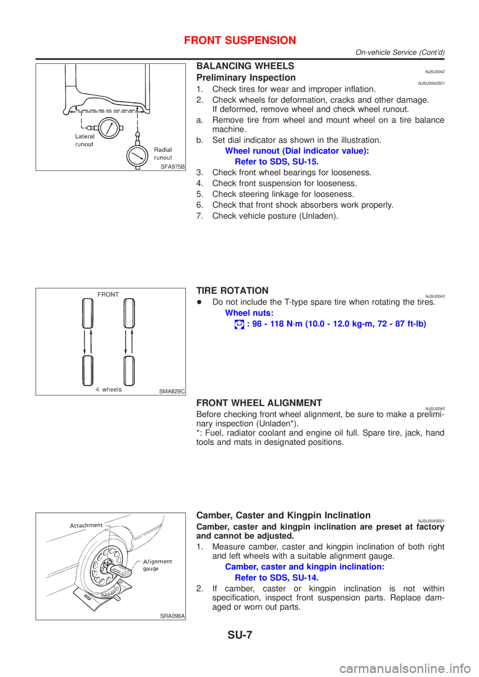
BALANCING WHEELSNJSU0042Preliminary InspectionNJSU0042S011. Check tires for wear and improper inflation.
2. Check wheels for deformation, cracks and other damage.
If deformed, remove wheel and check wheel runout.
a. Remove tire from wheel and mount wheel on a tire balance
machine.
b. Set dial indicator as shown in the illustration.
Wheel runout (Dial indicator value):
Refer to SDS, SU-15.
3. Check front wheel bearings for looseness.
4. Check front suspension for looseness.
5. Check steering linkage for looseness.
6. Check that front shock absorbers work properly.
7. Check vehicle posture (Unladen).
SMA829C
TIRE ROTATIONNJSU0043+Do not include the T-type spare tire when rotating the tires.
Wheel nuts:
: 98 - 118 N´m (10.0 - 12.0 kg-m, 72 - 87 ft-lb)
FRONT WHEEL ALIGNMENTNJSU0045Before checking front wheel alignment, be sure to make a prelimi-
nary inspection (Unladen*).
*: Fuel, radiator coolant and engine oil full. Spare tire, jack, hand
tools and mats in designated positions.
SRA096A
Camber, Caster and Kingpin InclinationNJSU0045S01Camber, caster and kingpin inclination are preset at factory
and cannot be adjusted.
1. Measure camber, caster and kingpin inclination of both right
and left wheels with a suitable alignment gauge.
Camber, caster and kingpin inclination:
Refer to SDS, SU-14.
2. If camber, caster or kingpin inclination is not within
specification, inspect front suspension parts. Replace dam-
aged or worn out parts.
FRONT SUSPENSION
On-vehicle Service (Cont'd)
SU-7
Page 2881 of 2898
Coil Spring and Shock Absorber
COMPONENTS=NJSU0008
NAX012
1. Strut mount upper plate
2. Strut spacer
3. Strut mount insulator
4. Thrust bearing
5. Upper spring seat
6. Upper rubber seat
7. Bound bumper rubber
8. Coil spring
9. Shock absorber10. Wheel hub and steering knuckle
11. Cotter pin
12. Washer
13. Bush
14. Transverse link
15. Bush
16. Washer
17. Connecting rod
18. Member pin stay19. Suspension member
20. Washer
21. Bush
22. Washer
23. Bush
24. Clamp
25. Stabilizer
26. Washer
FRONT SUSPENSION
Coil Spring and Shock Absorber
SU-9
Page 2882 of 2898

SFA956A
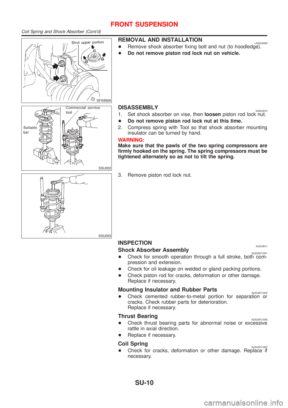
REMOVAL AND INSTALLATION=NJSU0009+Remove shock absorber fixing bolt and nut (to hoodledge).
+Do not remove piston rod lock nut on vehicle.
SSU002
DISASSEMBLYNJSU00101. Set shock absorber on vise, thenloosenpiston rod lock nut.
+Do not remove piston rod lock nut at this time.
2. Compress spring with Tool so that shock absorber mounting
insulator can be turned by hand.
WARNING:
Make sure that the pawls of the two spring compressors are
firmly hooked on the spring. The spring compressors must be
tightened alternately so as not to tilt the spring.
SSU003
3. Remove piston rod lock nut.
INSPECTIONNJSU0011Shock Absorber AssemblyNJSU0011S01+Check for smooth operation through a full stroke, both com-
pression and extension.
+Check for oil leakage on welded or gland packing portions.
+Check piston rod for cracks, deformation or other damage.
Replace if necessary.
Mounting Insulator and Rubber PartsNJSU0011S02+Check cemented rubber-to-metal portion for separation or
cracks. Check rubber parts for deterioration.
Replace if necessary.
Thrust BearingNJSU0011S06+Check thrust bearing parts for abnormal noise or excessive
rattle in axial direction.
+Replace if necessary.
Coil SpringNJSU0011S03+Check for cracks, deformation or other damage. Replace if
necessary.
FRONT SUSPENSION
Coil Spring and Shock Absorber (Cont'd)
SU-10
Page 2883 of 2898
SFA508A
ASSEMBLYNJSU0012+When installing coil spring on strut, it must be positioned as
shown in the figure at left.
SFA957A
+When installing spring seat, make sure that it is positioned as
shown.
SSU035
Stabilizer Bar
REMOVAL AND INSTALLATIONNJSU0017+Remove stabilizer bar.
SFA625B
+When installing stabilizer, make sure paint and clamp face in
their correct directions.
SSU035
+When removing and installing stabilizer bar.
FRONT SUSPENSION
Coil Spring and Shock Absorber (Cont'd)
SU-11
Page 2886 of 2898

Service Data and Specifications (SDS)
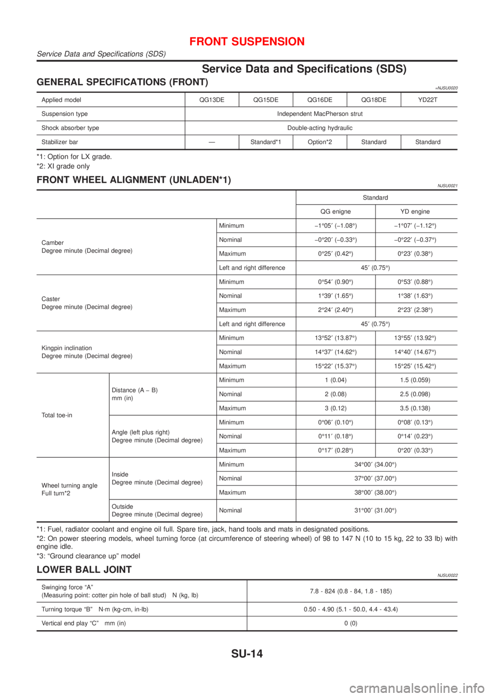
GENERAL SPECIFICATIONS (FRONT)=NJSU0020
Applied model QG13DE QG15DE QG16DE QG18DE YD22T
Suspension type Independent MacPherson strut
Shock absorber type Double-acting hydraulic
Stabilizer bar Ð Standard*1 Option*2 Standard Standard
*1: Option for LX grade.
*2: XI grade only
FRONT WHEEL ALIGNMENT (UNLADEN*1)NJSU0021
Standard
QG enigne YD engine
Camber
Degree minute (Decimal degree)Minimum þ1É05¢(þ1.08É) þ1É07¢(þ1.12É)
Nominal þ0É20¢(þ0.33É) þ0É22¢(þ0.37É)
Maximum 0É25¢(0.42É) 0É23¢(0.38É)
Left and right difference 45¢(0.75É)
Caster
Degree minute (Decimal degree)Minimum 0É54¢(0.90É) 0É53¢(0.88É)
Nominal 1É39¢(1.65É) 1É38¢(1.63É)
Maximum 2É24¢(2.40É) 2É23¢(2.38É)
Left and right difference 45¢(0.75É)
Kingpin inclination
Degree minute (Decimal degree)Minimum 13É52¢(13.87É) 13É55¢(13.92É)
Nominal 14É37¢(14.62É) 14É40¢(14.67É)
Maximum 15É22¢(15.37É) 15É25¢(15.42É)
Total toe-inDistance (A þ B)
mm (in)Minimum 1 (0.04) 1.5 (0.059)
Nominal 2 (0.08) 2.5 (0.098)
Maximum 3 (0.12) 3.5 (0.138)
Angle (left plus right)
Degree minute (Decimal degree)Minimum 0É06¢(0.10É) 0É08¢(0.13É)
Nominal 0É11¢(0.18É) 0É14¢(0.23É)
Maximum 0É17¢(0.28É) 0É20¢(0.33É)
Wheel turning angle
Full turn*2Inside
Degree minute (Decimal degree)Minimum 34É00¢(34.00É)
Nominal 37É00¢(37.00É)
Maximum 38É00¢(38.00É)
Outside
Degree minute (Decimal degree)Nominal 31É00¢(31.00É)
*1: Fuel, radiator coolant and engine oil full. Spare tire, jack, hand tools and mats in designated positions.
*2: On power steering models, wheel turning force (at circumference of steering wheel) of 98 to 147 N (10 to 15 kg, 22 to 33 lb) with
engine idle.
*3: ªGround clearance upº model
LOWER BALL JOINTNJSU0022
Swinging force ªAº
(Measuring point: cotter pin hole of ball stud) N (kg, lb)7.8 - 824 (0.8 - 84, 1.8 - 185)
Turning torque ªBº N´m (kg-cm, in-lb) 0.50 - 4.90 (5.1 - 50.0, 4.4 - 43.4)
Vertical end play ªCº mm (in)0 (0)
FRONT SUSPENSION
Service Data and Specifications (SDS)
SU-14
Page 2887 of 2898
WHEELARCH HEIGHT (UNLADEN*1)NJSU0041
SFA818A
Applied modelQG engine YD engine QG engine YD engine
Sedan Hatchback
185/65R15 195/60R15 185/65R15 195/60R15 185/65R15 195/60R15 185/65R15 195/60R15
Front (Hf)
mm (in)666 (26.22) 664 (26.14) 665 (26.18) 665 (26.18) 670 (26.38) 667 (26.26) 668 (26.30) 665 (26.18)
Rear (Hr)
mm (in)657 (25.87) 655 (25.79) 657 (25.87) 655 (25.79) 658 (25.91) 654 (25.75) 658 (25.91) 654 (25.75)
*1: Fuel, radiator coolant and engine oil full. Spare tire, jack, hand tools and mats in designated positions.
*2: ªGround clearance upº model
WHEEL RUNOUTNJSU0023
Wheel typeAluminum Steel wheel
Radial runout limit mm (in) 0.3 (0.012) 0.5 (0.020)
Lateral runout limit mm (in) 0.3 (0.012) 0.8 (0.031)
WHEEL BALANCENJSU0044
Maximum allowable unbalanceDynamic (At rim flange) g (oz) 10 (0.35) (one side)
Static g (oz) 20 (0.71)
FRONT SUSPENSION
Service Data and Specifications (SDS) (Cont'd)
SU-15