Page 2852 of 2898
ComponentsNJST0021
SST997C
1. Rear cover cap
2. Gear sub-assembly
3. O-ring
4. Shim
5. Lock nut
6. Adjusting screw
7. Spring
8. Spring seat
9. Retainer10. Gear housing
11. Center bushing
12. Rack oil seal
13. Rack assembly
14. Rack seal ring
15. O-ring
16. Rack oil seal
17. End cover assembly
18. Boot band19. Dust boot
20. Boot band
21. Spacer ring
22. Lock plate
23. Tie-rod inner socket
24. Tie-rod outer socket
25. Cotter pin
26. Gear cylinder tube
POWER STEERING GEAR AND LINKAGE
Components
ST-16
Page 2855 of 2898

SST051C
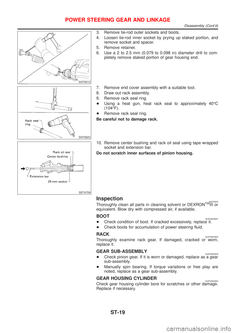
3. Remove tie-rod outer sockets and boots.
4. Loosen tie-rod inner socket by prying up staked portion, and
remove socket and spacer.
5. Remove retainer.
6. Usea2to2.5mm(0.079 to 0.098 in) diameter drill to com-
pletely remove staked portion of gear housing end.
SST052C
7. Remove end cover assembly with a suitable tool.
8. Draw out rack assembly.
9. Remove rack seal ring.
+Using a heat gun, heat rack seal to approximately 40ÉC
(104ÉF).
+Remove rack seal ring.
Be careful not to damage rack.
SST472A
10. Remove center bushing and rack oil seal using tape wrapped
socket and extension bar.
Do not scratch inner surfaces of pinion housing.
InspectionNJST0024Thoroughly clean all parts in cleaning solvent or DEXRONTMIII or
equivalent. Blow dry with compressed air, if available.
BOOTNJST0024S01+Check condition of boot. If cracked excessively, replace it.
+Check boots for accumulation of power steering fluid.
RACKNJST0024S02Thoroughly examine rack gear. If damaged, cracked or worn,
replace it.
GEAR SUB-ASSEMBLYNJST0024S03+Check pinion gear. If it is worn or damaged, replace as a gear
sub-assembly.
+Manually spin bearing. If torque variations or free play are
noted, replace as a gear sub-assembly.
GEAR HOUSING CYLINDERNJST0024S04Check gear housing cylinder bore for scratches or other damage.
Replace if necessary.
POWER STEERING GEAR AND LINKAGE
Disassembly (Cont'd)
ST-19
Page 2856 of 2898

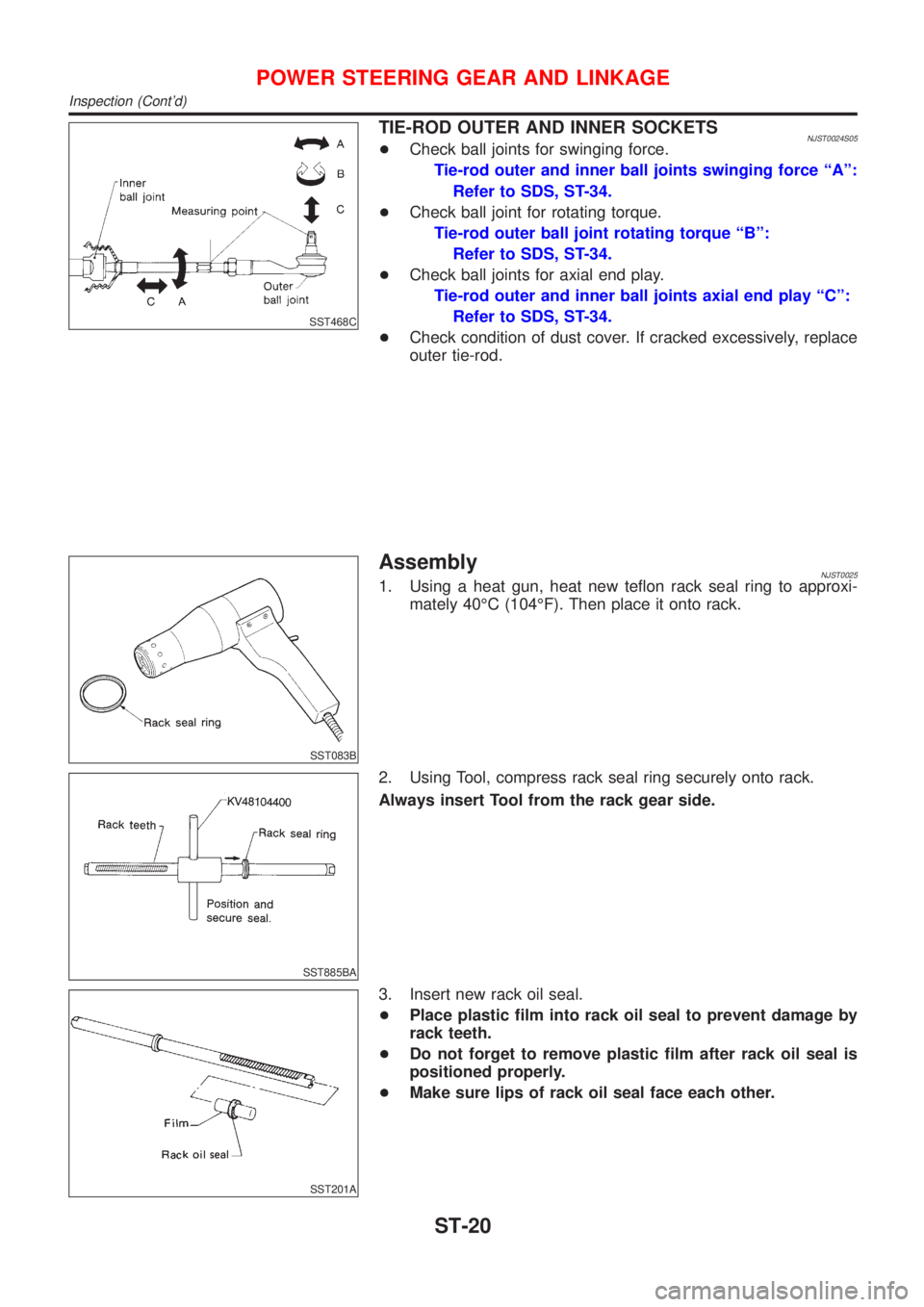
SST468C
TIE-ROD OUTER AND INNER SOCKETSNJST0024S05+Check ball joints for swinging force.
Tie-rod outer and inner ball joints swinging force ªAº:
Refer to SDS, ST-34.
+Check ball joint for rotating torque.
Tie-rod outer ball joint rotating torque ªBº:
Refer to SDS, ST-34.
+Check ball joints for axial end play.
Tie-rod outer and inner ball joints axial end play ªCº:
Refer to SDS, ST-34.
+Check condition of dust cover. If cracked excessively, replace
outer tie-rod.
SST083B
AssemblyNJST00251. Using a heat gun, heat new teflon rack seal ring to approxi-
mately 40ÉC (104ÉF). Then place it onto rack.
SST885BA
2. Using Tool, compress rack seal ring securely onto rack.
Always insert Tool from the rack gear side.
SST201A
3. Insert new rack oil seal.
+Place plastic film into rack oil seal to prevent damage by
rack teeth.
+Do not forget to remove plastic film after rack oil seal is
positioned properly.
+Make sure lips of rack oil seal face each other.
POWER STEERING GEAR AND LINKAGE
Inspection (Cont'd)
ST-20
Page 2857 of 2898
SST863C
4. Install center bushing and rack oil seal with rack assembly.
SST321B
5. Insert rack oil seal and end cover assembly to rack. Then
tighten end cover assembly.
SST073B
6. Fasten end cover assembly to gear housing by staking.
SST086BA
7. Set rack gear in neutral position.
Rack stroke ªSº:
Refer to SDS, ST-34.
SST880C
8. Install adjustment shims and O-rings to gear sub-assembly.
+Install the same number of adjustment shims as before,
regardless of whether or not gear sub-assembly is replaced.
+Discard old O-rings; replace with new ones.
9. Tighten gear subassembly securing bolts to specified tighten-
ing torque.
POWER STEERING GEAR AND LINKAGE
Assembly (Cont'd)
ST-21
Page 2861 of 2898
ComponentsNJST0027
SST881CA
1. Pulley
2. Bracket
3. Drive shaft seal
4. Inlet connector
5. Inlet connector seal
6. Front housing
7. Flow control valve spring8. Flow control A valve
9. Dowel pin
10. Flow control B valve assy
11. Front side plate
12. Cartridge
13. Rotor
14. Vane15. Rotor snap ring
16. Rear side plate
17. Side plate inner seal
18. Side plate outer seal
19. Body seal
20. Rear body
SST984A
Pre-disassembly InspectionNJST0028Disassemble the power steering oil pump only if the following items
are found.
+Oil leak from any point shown in the figure
+Deformed or damaged pulley
+Poor performance
POWER STEERING OIL PUMP (QG ENGINE)
Components
ST-25
Page 2862 of 2898
DisassemblyNJST0029CAUTION:
+The power steering pump cannot be disassembled on
Hatchback with QG engine. If it is faulty, replae with a new
assembly.
+Parts which can be disassembled are strictly limited.
Never disassemble parts other than those specified.
+Disassemble in as clean a place as possible.
+Clean your hands before disassembly.
+Do not use rags; use nylon cloths or paper towels.
+Follow the procedures and cautions in the Service
Manual.
+When disassembling and reassembling, do not let foreign
matter enter or contact the parts.
SST010B
+Remove snap ring, then draw drive shaft out.
Be careful not to drop drive shaft.
SST034A
+Remove oil seal.
Be careful not to damage front housing.
SST036A
+Remove connector and flow control valve with spring.
Be careful not to drop flow control valve.
Do not disassemble flow control valve.
POWER STEERING OIL PUMP (QG ENGINE)
Disassembly
ST-26
Page 2863 of 2898
InspectionNJST0030+If pulley is cracked or deformed, replace it.
+If an oil leak is found around pulley shaft oil seal, replace the
seal.
+If serration on pulley or pulley shaft is deformed or worn,
replace it.
SST038A
AssemblyNJST0031Assemble oil pump, noting the following instructions.
+Make sure O-rings and oil seal are properly installed.
+Always install new O-rings and oil seal.
+Be careful of oil seal direction.
+Cam ring, rotor and vanes must be replaced as a set if neces-
sary.
+Coat each part with DEXRON
TMIII or equivalent when assem-
bling.
SST289A
+Pay attention to the direction of rotor.
SST843A
+When assembling vanes to rotor, rounded surfaces of vanes
must face cam ring side.
POWER STEERING OIL PUMP (QG ENGINE)
Inspection
ST-27
Page 2864 of 2898
SST472C
+Insert pin 2 into pin groove 1 of front housing and front side
plate. Then install cam ring 3 as shown at left.
Cam ring:
D
1is less than D2.
POWER STEERING OIL PUMP (QG ENGINE)
Assembly (Cont'd)
ST-28