Page 2662 of 2898

SMT747D
a. Using dial gauge as shown in the figure, measure dimension
ªP1º between transaxle case end face and mainshaft rear
bearing.
SMT748D
b. Using dial gauge as shown in the figure, measure dimension
ªP2º between adjusting shim mounting face of rear cover and
transaxle mounting face.
SMT646D
16. Using snap ring pliers as shown in the figure, install snap ring.
CAUTION:
Do not reuse snap ring.
17. Install selected mainshaft adjusting shim.
SMT753DA
18. Install reverse idler gear, O-ring, thrust washers (front, rear),
and bearing onto reverse idler shaft.
19. Install snap ring into transaxle case using snap ring pliers.
CAUTION:
+Do not reuse snap ring.
+Do not reuse O-ring.
+Before installation, apply gear oil to O-ring.
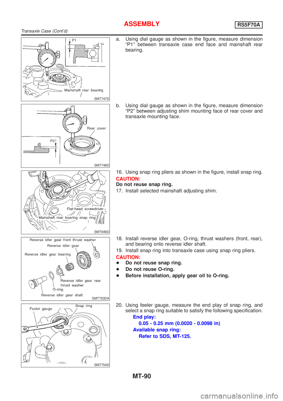
SMT754D
20. Using feeler gauge, measure the end play of snap ring, and
select a snap ring suitable to satisfy the following specification.
End play:
0.05 - 0.25 mm (0.0020 - 0.0098 in)
Available snap ring:
Refer to SDS, MT-125.
ASSEMBLYRS5F70A
Transaxle Case (Cont'd)
MT-90
Page 2663 of 2898
SMT644D
21. Install selected snap ring.
CAUTION:
Do not reuse snap ring.
22. Apply gear oil to rear cover O-ring, and install rear cover, side
cover gasket, and side cover. Then tighten mounting bolts with
specified torque.
Tightening torque:
Refer to MT-54.
CAUTION:
Do not reuse mounting bolts for rear cover and side cover.
ASSEMBLYRS5F70A
Transaxle Case (Cont'd)
MT-91
Page 2664 of 2898
NJMT0009
Case ComponentsNJMT0009S02
SMT943D
1. Speedometer pinion
2. Differential oil seal
3. Drain plug
4. Boot
5. Striking rod oil seal
6. Magnet
7. Clutch housing8. Input shaft oil seal
9. Oil channel (Mainshaft)
10. Oil pocket
11. Oil gutter
12. Oil channel (Input shaft)
13. Transmission case14. Filler plug
15. O-ring
16. Movable plate assembly
17. PNP switch
18. Breather hose
19. Breather pipe
OVERHAULRS5F50A
Case Components
MT-92
Page 2668 of 2898
SMT662C
7. Remove reverse arm shaft while rotating it.
SMT663C
8. Remove reverse lever assembly and check ball.
+Be careful not to lose check ball.
SMT018B
9. Remove 5th & reverse check plug, spring and ball.
+Be careful not to lose check ball.
SMT664C
10. Remove stopper rings and retaining pins from 5th and 3rd &
4th fork rods.
When removing stopper rings. Use snap ring remover and
installer.
11. Remove 5th and 3rd & 4th fork rods. Then remove forks and
brackets.
SMT105C
12. Remove both input and mainshafts with 1st & 2nd fork and fork
rod as a set.
13. Remove final drive assembly.
+Always withdraw mainshaft straight out. Failure to do so
can damage resin oil channel on clutch housing side.
DISASSEMBLYRS5F50A
MT-96
Page 2681 of 2898
SMT609A
5. Install final gear.
6. Install speedometer drive gear.
SMT648
7. Press on differential side bearings.
SMT665C
Shift Control Components
INSPECTIONNJMT0020+Check contact surface and sliding surface for wear, scratches,
projections or other damage.
SMT030A
Case Components
REMOVAL AND INSTALLATIONNJMT0021Input Shaft Oil SealNJMT0021S01
REPAIR FOR COMPONENT PARTSRS5F50A
Final Drive (Cont'd)
MT-109
Page 2682 of 2898
SMT031A
+Apply multi-purpose grease to seal lip of oil seal before
installing.
SMT034A
Mainshaft Front Bearing Outer RaceNJMT0021S02+Extract the oil channel and remove the mainshaft front bear-
ing outer race.
Mainshaft Rear Bearing Outer RaceNJMT0021S03Refer to ªMainshaft Bearing Preloadº, MT-134.
Differential Side Bearing Outer RaceNJMT0021S04Refer to ªInput Shaft End Play and Differential Side Bearing
Preloadº, MT-134.
REPAIR FOR COMPONENT PARTSRS5F50A
Case Components (Cont'd)
MT-110
Page 2686 of 2898
NJMT0093
SMT029AA
1. Install striking lever and striking rod.
SMT645AA
2. Install selector and retaining pin.
SMT138A
3. Install check ball and reverse check assembly.
+Before installation, rotate striking rod as shown in the fig-
ure to avoid interference.
SAT601C
4. Install final drive assembly.
5. Install input shaft and mainshaft with 1st & 2nd shift fork
assembly.
+Be careful not to damage input shaft oil seal.
SMT065A
6. Install interlock balls and plunger.
ASSEMBLYRS5F50A
MT-114
Page 2690 of 2898
General SpecificationsNJMT0068TRANSAXLENJMT0068S01
Applied modelEurope
QG15DE
Model code number4M506
Transaxle modelRS5F30A
Number of speeds5
Synchromesh typeWarner
Shift pattern
Gear ratio 1st3.333
2nd1.782
3rd1.207
4th0.902
5th0.756
Reverse 3.417
Number of teeth Input gear 1st 15
2nd 23
3rd 29
4th 41
5th 45
Rev. 12
Main gear 1st 50
2nd 41
3rd 35
4th 37
5th 34
Rev. 41
Reverse idler gear 30
Oil capacity!(Imp pt)2.8 - 3.0 (4-7/8 - 5-1/4)
Oil level (Reference data) mm (in) 58 - 66 (2.28 - 2.60)
Remarks1st & 2nd double baulk ring type synchronizer (where fitted)
FINAL GEARNJMT0068S02
EngineQG15DE
Final gear ratio4.167
Number of teethFinal gear/Pinion 75/18
Side gear/Pinion mate gear 14/10
SERVICE DATA AND SPECIFICATIONS (SDS)RS5F30A
General Specifications
MT-118