Page 2592 of 2898
SMT563AA
Replacing Oil SealNJMT0035DIFFERENTIAL OIL SEALNJMT0035S011. Drain gear oil from transaxle.
2. Remove drive shafts. Refer to AX-11, ªRemovalº.
3. Remove differential oil seal.
SMT564AB
SMT925DA
4. Install differential oil seal.
+Apply multi-purpose grease to seal lip of oil seal before
installing.
5. Install drive shafts. Refer to AX-12, ªInstallationº.
SMT926DA
SMT927D
+Install differential oil seal so that dimension ªAº and ªBº
are within specifications.
Unit: mm (in)
Item Model A B
DimensionRS5F30A
þ0.5 (þ0.020) to 0.5 (0.020) RS5F70A
RS5F50A
ON-VEHICLE SERVICE
Replacing Oil Seal
MT-20
Page 2593 of 2898
SMT143DC
STRIKING ROD OIL SEALNJMT0035S021. Remove transaxle control rod from yoke.
2. Remove retaining pin of yoke.
+Be careful not to damage boot.
SMT566A
3. Remove striking rod oil seal.
SMT570A
4. Install striking rod oil seal.
+Apply multi-purpose grease to seal lip of oil seal before
installing.
SMT876D
+Drive it in as far as it will go.
SMT715BD
Position Switch CheckNJMT0036BACK-UP LAMP SWITCHNJMT0036S01Ð RS5F30A and RS5F70A ÐNJMT0036S0101+Check continuity.
Gear position Continuity
Reverse Yes
Except reverse No
ON-VEHICLE SERVICE
Replacing Oil Seal (Cont'd)
MT-21
Page 2595 of 2898

NJMT0008
SMT928D
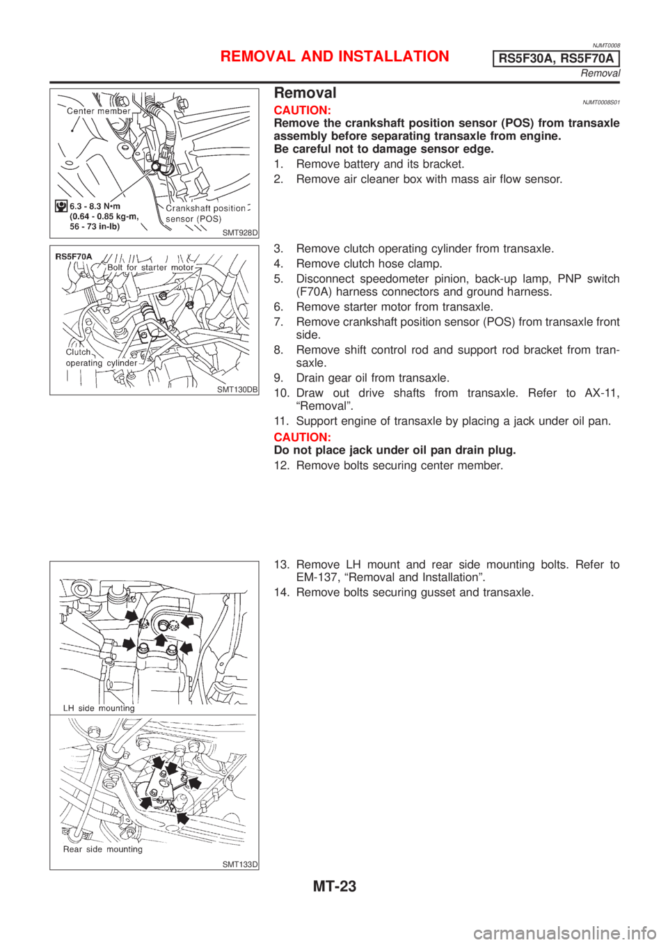
RemovalNJMT0008S01CAUTION:
Remove the crankshaft position sensor (POS) from transaxle
assembly before separating transaxle from engine.
Be careful not to damage sensor edge.
1. Remove battery and its bracket.
2. Remove air cleaner box with mass air flow sensor.
SMT130DB
3. Remove clutch operating cylinder from transaxle.
4. Remove clutch hose clamp.
5. Disconnect speedometer pinion, back-up lamp, PNP switch
(F70A) harness connectors and ground harness.
6. Remove starter motor from transaxle.
7. Remove crankshaft position sensor (POS) from transaxle front
side.
8. Remove shift control rod and support rod bracket from tran-
saxle.
9. Drain gear oil from transaxle.
10. Draw out drive shafts from transaxle. Refer to AX-11,
ªRemovalº.
11. Support engine of transaxle by placing a jack under oil pan.
CAUTION:
Do not place jack under oil pan drain plug.
12. Remove bolts securing center member.
SMT133D
13. Remove LH mount and rear side mounting bolts. Refer to
EM-137, ªRemoval and Installationº.
14. Remove bolts securing gusset and transaxle.
REMOVAL AND INSTALLATIONRS5F30A, RS5F70A
Removal
MT-23
Page 2598 of 2898

NJMT0090
SMT928D
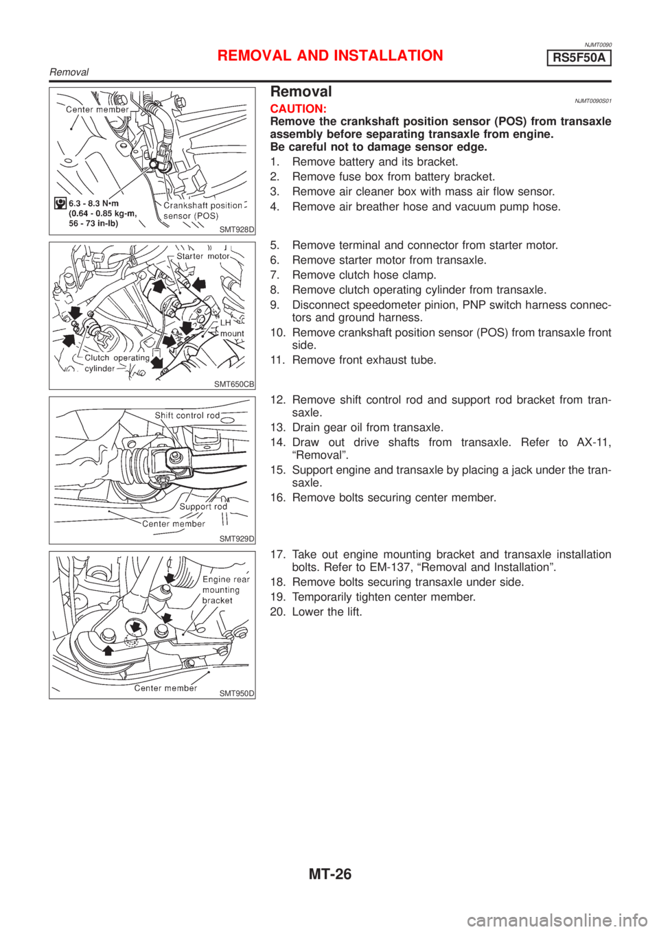
RemovalNJMT0090S01CAUTION:
Remove the crankshaft position sensor (POS) from transaxle
assembly before separating transaxle from engine.
Be careful not to damage sensor edge.
1. Remove battery and its bracket.
2. Remove fuse box from battery bracket.
3. Remove air cleaner box with mass air flow sensor.
4. Remove air breather hose and vacuum pump hose.
SMT650CB
5. Remove terminal and connector from starter motor.
6. Remove starter motor from transaxle.
7. Remove clutch hose clamp.
8. Remove clutch operating cylinder from transaxle.
9. Disconnect speedometer pinion, PNP switch harness connec-
tors and ground harness.
10. Remove crankshaft position sensor (POS) from transaxle front
side.
11. Remove front exhaust tube.
SMT929D
12. Remove shift control rod and support rod bracket from tran-
saxle.
13. Drain gear oil from transaxle.
14. Draw out drive shafts from transaxle. Refer to AX-11,
ªRemovalº.
15. Support engine and transaxle by placing a jack under the tran-
saxle.
16. Remove bolts securing center member.
SMT950D
17. Take out engine mounting bracket and transaxle installation
bolts. Refer to EM-137, ªRemoval and Installationº.
18. Remove bolts securing transaxle under side.
19. Temporarily tighten center member.
20. Lower the lift.
REMOVAL AND INSTALLATIONRS5F50A
Removal
MT-26
Page 2599 of 2898
SMT940D
SMT951D
21. Pick up EGI harness clamp and install engine slinger. Next, set
chain block.
22. Jack up the air compressor engine bracket.
23. Remove engine front mounting.
24. Remove LH side mounting. Refer to EM-137, ªRemoval and
Installationº.
SMT952D
25. Jack up until engine oil filter bracket bolts are just about to
touch the side frame.
SMT941D
26. Remove bolts securing transaxle.
27. While the transaxle is suspended, withdraw the transaxle case
from the engine without hitting suspension member.
+Open the front of the transaxle when the clutch cover
appears. Then, lower the transaxle pulling it toward the
right front.
+The spacer between the engine and transaxle should be
left at the engine side.
28. Remove spacer.
REMOVAL AND INSTALLATIONRS5F50A
Removal (Cont'd)
MT-27
Page 2602 of 2898
NJMT0039
Case ComponentsNJMT0039S01
SMT956DA
1. Clutch housing
2. Input shaft oil seal
3. Oil pocket
4. Bearing retainer
5. Torx screw
6. Filler plug
7. Air breather tube
8. Welch plug
9. O-ring10. Case cover
11. Back-up lamp switch
12. Differential oil seal
13. Drain plug
14. Transmission case
15. Oil gutter
16. Reverse idler shaft
17. Oil channel
18. Striking rod oil seal19. Boot
20. Differential oil seal
21. O-ring
22. Speedometer pinion assembly
23. Magnet
24. Earth term
25. Welch plug
26. Welch plug
27. PNP switch
OVERHAULRS5F30A
Case Components
MT-30
Page 2603 of 2898

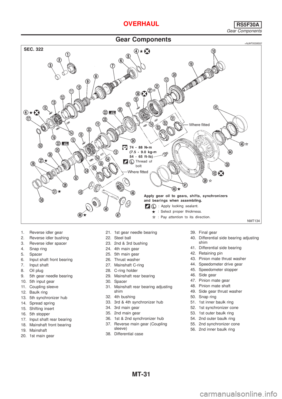
Gear Components=NJMT0039S02
NMT134
1. Reverse idler gear
2. Reverse idler bushing
3. Reverse idler spacer
4. Snap ring
5. Spacer
6. Input shaft front bearing
7. Input shaft
8. Oil plug
9. 5th gear needle bearing
10. 5th input gear
11. Coupling sleeve
12. Baulk ring
13. 5th synchronizer hub
14. Spread spring
15. Shifting insert
16. 5th stopper
17. Input shaft rear bearing
18. Mainshaft front bearing
19. Mainshaft
20. 1st main gear21. 1st gear needle bearing
22. Steel ball
23. 2nd & 3rd bushing
24. 4th main gear
25. 5th main gear
26. Thrust washer
27. Mainshaft C-ring
28. C-ring holder
29. Mainshaft rear bearing
30. Spacer
31. Mainshaft rear bearing adjusting
shim
32. 4th bushing
33. 3rd & 4th synchronizer hub
34. 3rd main gear
35. 2nd main gear
36. 1st & 2nd synchronizer hub
37. Reverse main gear (Coupling
sleeve)
38. Differential case39. Final gear
40. Differential side bearing adjusting
shim
41. Differential side bearing
42. Retaining pin
43. Pinion mate thrust washer
44. Speedometer drive gear
45. Speedometer stopper
46. Side gear
47. Pinion mate gear
48. Pinion mate shaft
49. Side gear thrust washer
50. Snap ring
51. 1st inner baulk ring
52. 1st synchronizer cone
53. 1st outer baulk ring
54. 2nd outer baulk ring
55. 2nd synchronizer cone
56. 2nd inner baulk ring
OVERHAULRS5F30A
Gear Components
MT-31
Page 2605 of 2898
NJMT0040
SMT571
1. Remove transmission case while slightly tilting it to prevent 5th
shift fork from interfering with case.
SMT188A
2. Draw out reverse idler spacer and fork shaft, then remove 5th
and 3rd & 4th shift forks.
+Be careful not to lose shifter cap.
SMT082A
3. Remove control bracket with 1st & 2nd shift fork.
+Be careful not to lose shifter cap.
SMT577
4. Remove gear components from clutch housing.
a. Remove three screws and detach bearing retainer.
+One of these three screws is torx type and should be
removed with a suitable tool, as shown.
SMT579
b. Remove input shaft together with mainshaft by tapping lightly.
+Always withdraw mainshaft straight out. Failure to do so
can damage resin oil channel on clutch housing side.
+Do not draw out reverse idler shaft from clutch housing
because these fittings will be loose.
+When removing input shaft, be careful not to scratch oil
seal lip with shaft spline.
DISASSEMBLYRS5F30A
MT-33