2001 NISSAN ALMERA oil
[x] Cancel search: oilPage 2695 of 2898
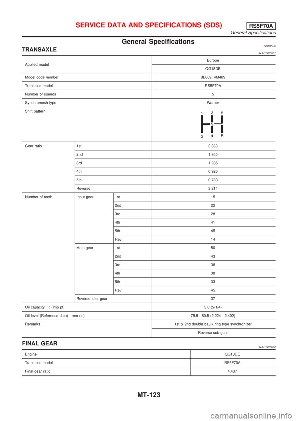
General SpecificationsNJMT0076TRANSAXLENJMT0076S01
Applied modelEurope
QG18DE
Model code number8E009, 4M469
Transaxle modelRS5F70A
Number of speeds5
Synchromesh typeWarner
Shift pattern
Gear ratio 1st3.333
2nd1.955
3rd1.286
4th0.926
5th0.733
Reverse 3.214
Number of teeth Input gear 1st 15
2nd 22
3rd 28
4th 41
5th 45
Rev. 14
Main gear 1st 50
2nd 43
3rd 36
4th 38
5th 33
Rev. 45
Reverse idler gear 37
Oil capacity!(Imp pt)3.0 (5-1/4)
Oil level (Reference data) mm (in) 75.5 - 80.5 (2.224 - 2.402)
Remarks1st & 2nd double baulk ring type synchronizer
Reverse sub-gear
FINAL GEARNJMT0076S02
EngineQG18DE
Transaxle modelRS5F70A
Final gear ratio4.437
SERVICE DATA AND SPECIFICATIONS (SDS)RS5F70A
General Specifications
MT-123
Page 2703 of 2898
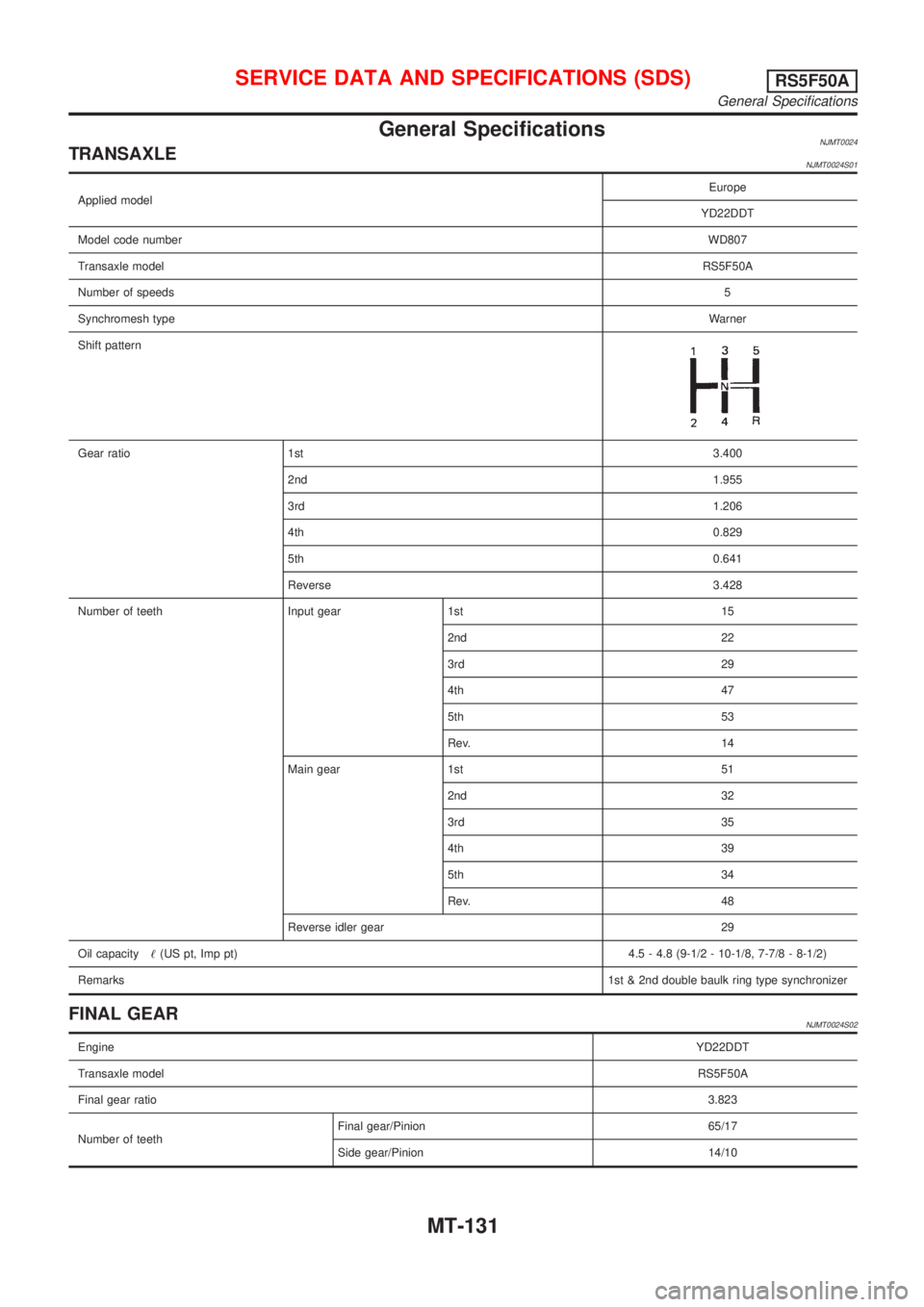
General SpecificationsNJMT0024TRANSAXLENJMT0024S01
Applied modelEurope
YD22DDT
Model code numberWD807
Transaxle modelRS5F50A
Number of speeds5
Synchromesh typeWarner
Shift pattern
Gear ratio 1st3.400
2nd1.955
3rd1.206
4th0.829
5th0.641
Reverse3.428
Number of teeth Input gear 1st 15
2nd 22
3rd 29
4th 47
5th 53
Rev. 14
Main gear 1st 51
2nd 32
3rd 35
4th 39
5th 34
Rev. 48
Reverse idler gear 29
Oil capacity!(US pt, Imp pt)4.5 - 4.8 (9-1/2 - 10-1/8, 7-7/8 - 8-1/2)
Remarks1st & 2nd double baulk ring type synchronizer
FINAL GEARNJMT0024S02
EngineYD22DDT
Transaxle modelRS5F50A
Final gear ratio3.823
Number of teethFinal gear/Pinion 65/17
Side gear/Pinion 14/10
SERVICE DATA AND SPECIFICATIONS (SDS)RS5F50A
General Specifications
MT-131
Page 2711 of 2898
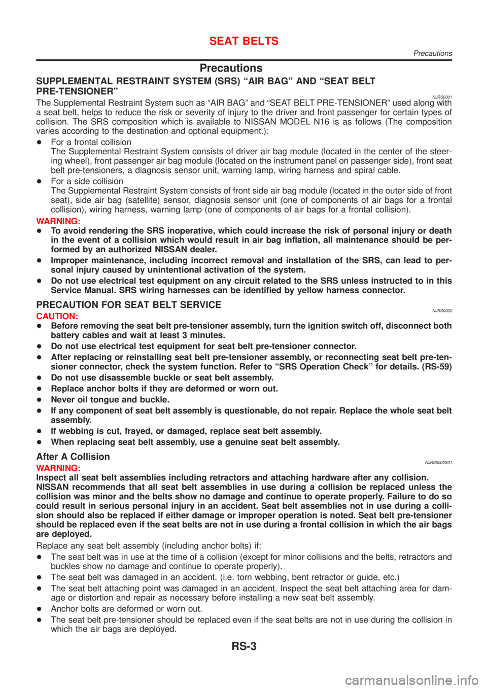
Precautions
SUPPLEMENTAL RESTRAINT SYSTEM (SRS) ªAIR BAGº AND ªSEAT BELT
PRE-TENSIONERº
NJRS0001The Supplemental Restraint System such as ªAIR BAGº and ªSEAT BELT PRE-TENSIONERº used along with
a seat belt, helps to reduce the risk or severity of injury to the driver and front passenger for certain types of
collision. The SRS composition which is available to NISSAN MODEL N16 is as follows (The composition
varies according to the destination and optional equipment.):
+For a frontal collision
The Supplemental Restraint System consists of driver air bag module (located in the center of the steer-
ing wheel), front passenger air bag module (located on the instrument panel on passenger side), front seat
belt pre-tensioners, a diagnosis sensor unit, warning lamp, wiring harness and spiral cable.
+For a side collision
The Supplemental Restraint System consists of front side air bag module (located in the outer side of front
seat), side air bag (satellite) sensor, diagnosis sensor unit (one of components of air bags for a frontal
collision), wiring harness, warning lamp (one of components of air bags for a frontal collision).
WARNING:
+To avoid rendering the SRS inoperative, which could increase the risk of personal injury or death
in the event of a collision which would result in air bag inflation, all maintenance should be per-
formed by an authorized NISSAN dealer.
+Improper maintenance, including incorrect removal and installation of the SRS, can lead to per-
sonal injury caused by unintentional activation of the system.
+Do not use electrical test equipment on any circuit related to the SRS unless instructed to in this
Service Manual. SRS wiring harnesses can be identified by yellow harness connector.
PRECAUTION FOR SEAT BELT SERVICENJRS0002CAUTION:
+Before removing the seat belt pre-tensioner assembly, turn the ignition switch off, disconnect both
battery cables and wait at least 3 minutes.
+Do not use electrical test equipment for seat belt pre-tensioner connector.
+After replacing or reinstalling seat belt pre-tensioner assembly, or reconnecting seat belt pre-ten-
sioner connector, check the system function. Refer to ªSRS Operation Checkº for details. (RS-59)
+Do not use disassemble buckle or seat belt assembly.
+Replace anchor bolts if they are deformed or worn out.
+Never oil tongue and buckle.
+If any component of seat belt assembly is questionable, do not repair. Replace the whole seat belt
assembly.
+If webbing is cut, frayed, or damaged, replace seat belt assembly.
+When replacing seat belt assembly, use a genuine seat belt assembly.
After A CollisionNJRS0002S01WARNING:
Inspect all seat belt assemblies including retractors and attaching hardware after any collision.
NISSAN recommends that all seat belt assemblies in use during a collision be replaced unless the
collision was minor and the belts show no damage and continue to operate properly. Failure to do so
could result in serious personal injury in an accident. Seat belt assemblies not in use during a colli-
sion should also be replaced if either damage or improper operation is noted. Seat belt pre-tensioner
should be replaced even if the seat belts are not in use during a frontal collision in which the air bags
are deployed.
Replace any seat belt assembly (including anchor bolts) if:
+The seat belt was in use at the time of a collision (except for minor collisions and the belts, retractors and
buckles show no damage and continue to operate properly).
+The seat belt was damaged in an accident. (i.e. torn webbing, bent retractor or guide, etc.)
+The seat belt attaching point was damaged in an accident. Inspect the seat belt attaching area for dam-
age or distortion and repair as necessary before installing a new seat belt assembly.
+Anchor bolts are deformed or worn out.
+The seat belt pre-tensioner should be replaced even if the seat belts are not in use during the collision in
which the air bags are deployed.
SEAT BELTS
Precautions
RS-3
Page 2738 of 2898
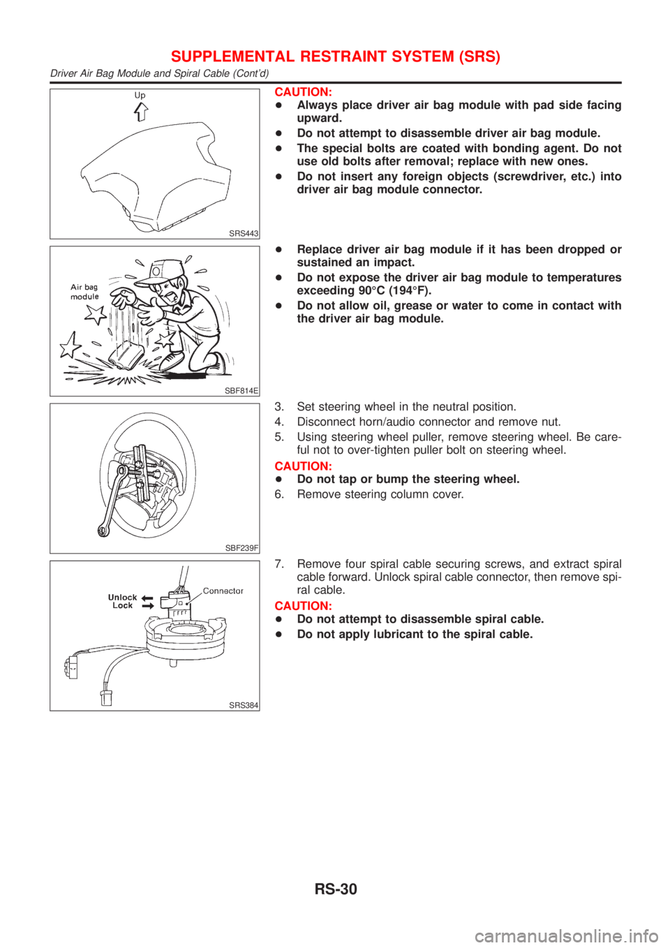
SRS443
CAUTION:
+Always place driver air bag module with pad side facing
upward.
+Do not attempt to disassemble driver air bag module.
+The special bolts are coated with bonding agent. Do not
use old bolts after removal; replace with new ones.
+Do not insert any foreign objects (screwdriver, etc.) into
driver air bag module connector.
SBF814E
+Replace driver air bag module if it has been dropped or
sustained an impact.
+Do not expose the driver air bag module to temperatures
exceeding 90ÉC (194ÉF).
+Do not allow oil, grease or water to come in contact with
the driver air bag module.
SBF239F
3. Set steering wheel in the neutral position.
4. Disconnect horn/audio connector and remove nut.
5. Using steering wheel puller, remove steering wheel. Be care-
ful not to over-tighten puller bolt on steering wheel.
CAUTION:
+Do not tap or bump the steering wheel.
6. Remove steering column cover.
SRS384
7. Remove four spiral cable securing screws, and extract spiral
cable forward. Unlock spiral cable connector, then remove spi-
ral cable.
CAUTION:
+Do not attempt to disassemble spiral cable.
+Do not apply lubricant to the spiral cable.
SUPPLEMENTAL RESTRAINT SYSTEM (SRS)
Driver Air Bag Module and Spiral Cable (Cont'd)
RS-30
Page 2741 of 2898
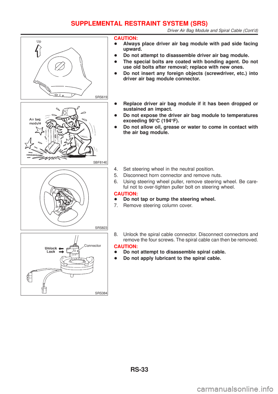
SRS619
CAUTION:
+Always place driver air bag module with pad side facing
upward.
+Do not attempt to disassemble driver air bag module.
+The special bolts are coated with bonding agent. Do not
use old bolts after removal; replace with new ones.
+Do not insert any foreign objects (screwdriver, etc.) into
driver air bag module connector.
SBF814E
+Replace driver air bag module if it has been dropped or
sustained an impact.
+Do not expose the driver air bag module to temperatures
exceeding 90ÉC (194ÉF).
+Do not allow oil, grease or water to come in contact with
the air bag module.
SRS823
4. Set steering wheel in the neutral position.
5. Disconnect horn connector and remove nuts.
6. Using steering wheel puller, remove steering wheel. Be care-
ful not to over-tighten puller bolt on steering wheel.
CAUTION:
+Do not tap or bump the steering wheel.
7. Remove steering column cover.
SRS384
8. Unlock the spiral cable connector. Disconnect connectors and
remove the four screws. The spiral cable can then be removed.
CAUTION:
+Do not attempt to disassemble spiral cable.
+Do not apply lubricant to the spiral cable.
SUPPLEMENTAL RESTRAINT SYSTEM (SRS)
Driver Air Bag Module and Spiral Cable (Cont'd)
RS-33
Page 2744 of 2898
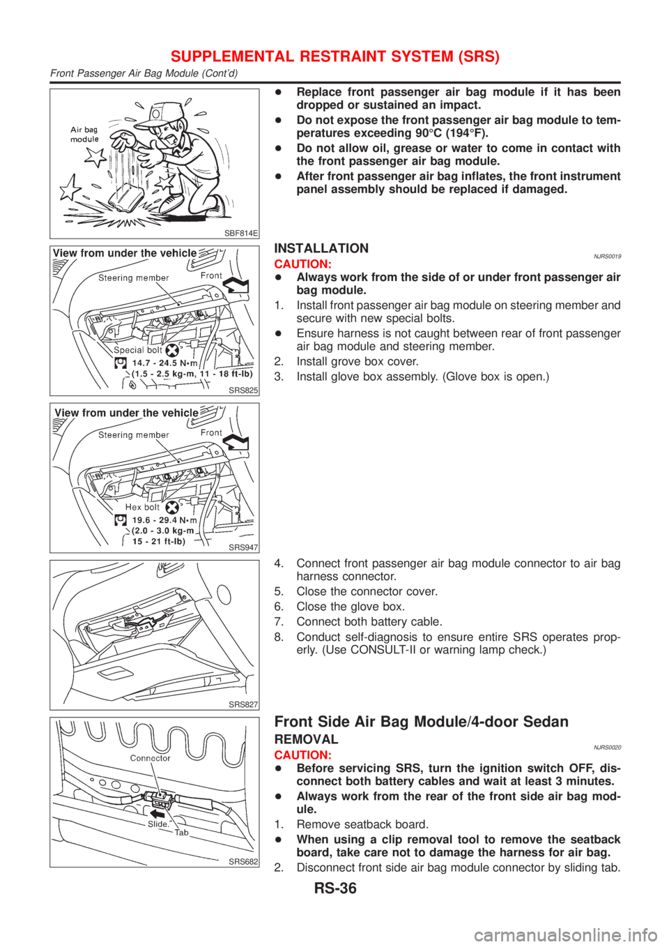
SBF814E
+Replace front passenger air bag module if it has been
dropped or sustained an impact.
+Do not expose the front passenger air bag module to tem-
peratures exceeding 90ÉC (194ÉF).
+Do not allow oil, grease or water to come in contact with
the front passenger air bag module.
+After front passenger air bag inflates, the front instrument
panel assembly should be replaced if damaged.
SRS825
SRS947
INSTALLATIONNJRS0019CAUTION:
+Always work from the side of or under front passenger air
bag module.
1. Install front passenger air bag module on steering member and
secure with new special bolts.
+Ensure harness is not caught between rear of front passenger
air bag module and steering member.
2. Install grove box cover.
3. Install glove box assembly. (Glove box is open.)
SRS827
4. Connect front passenger air bag module connector to air bag
harness connector.
5. Close the connector cover.
6. Close the glove box.
7. Connect both battery cable.
8. Conduct self-diagnosis to ensure entire SRS operates prop-
erly. (Use CONSULT-II or warning lamp check.)
SRS682
Front Side Air Bag Module/4-door Sedan
REMOVALNJRS0020CAUTION:
+Before servicing SRS, turn the ignition switch OFF, dis-
connect both battery cables and wait at least 3 minutes.
+Always work from the rear of the front side air bag mod-
ule.
1. Remove seatback board.
+When using a clip removal tool to remove the seatback
board, take care not to damage the harness for air bag.
2. Disconnect front side air bag module connector by sliding tab.
SUPPLEMENTAL RESTRAINT SYSTEM (SRS)
Front Passenger Air Bag Module (Cont'd)
RS-36
Page 2745 of 2898
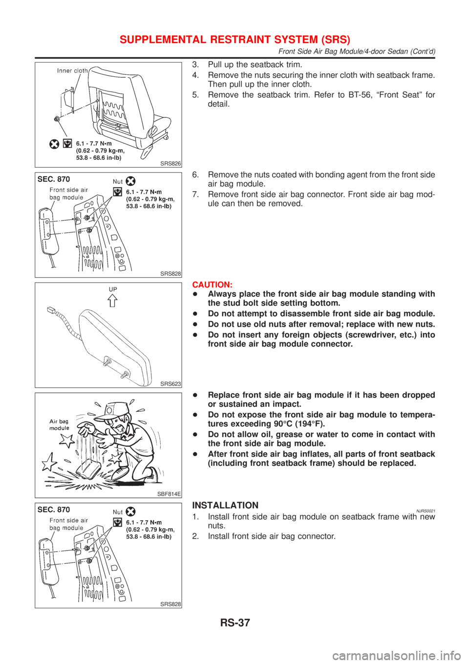
SRS826
3. Pull up the seatback trim.
4. Remove the nuts securing the inner cloth with seatback frame.
Then pull up the inner cloth.
5. Remove the seatback trim. Refer to BT-56, ªFront Seatº for
detail.
SRS828
6. Remove the nuts coated with bonding agent from the front side
air bag module.
7. Remove front side air bag connector. Front side air bag mod-
ule can then be removed.
SRS623
CAUTION:
+Always place the front side air bag module standing with
the stud bolt side setting bottom.
+Do not attempt to disassemble front side air bag module.
+Do not use old nuts after removal; replace with new nuts.
+Do not insert any foreign objects (screwdriver, etc.) into
front side air bag module connector.
SBF814E
+Replace front side air bag module if it has been dropped
or sustained an impact.
+Do not expose the front side air bag module to tempera-
tures exceeding 90ÉC (194ÉF).
+Do not allow oil, grease or water to come in contact with
the front side air bag module.
+After front side air bag inflates, all parts of front seatback
(including front seatback frame) should be replaced.
SRS828
INSTALLATIONNJRS00211. Install front side air bag module on seatback frame with new
nuts.
2. Install front side air bag connector.
SUPPLEMENTAL RESTRAINT SYSTEM (SRS)
Front Side Air Bag Module/4-door Sedan (Cont'd)
RS-37
Page 2747 of 2898
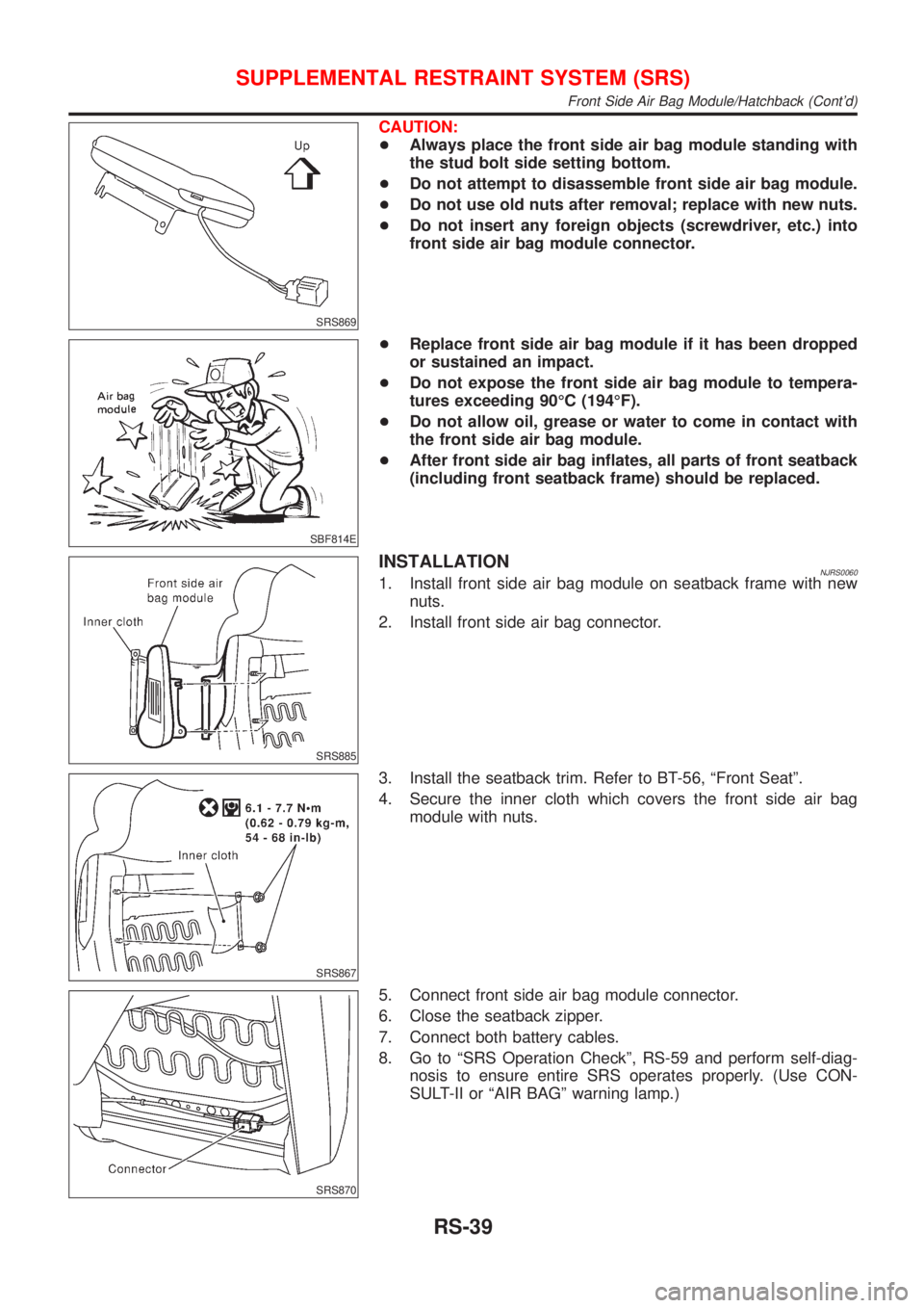
SRS869
CAUTION:
+Always place the front side air bag module standing with
the stud bolt side setting bottom.
+Do not attempt to disassemble front side air bag module.
+Do not use old nuts after removal; replace with new nuts.
+Do not insert any foreign objects (screwdriver, etc.) into
front side air bag module connector.
SBF814E
+Replace front side air bag module if it has been dropped
or sustained an impact.
+Do not expose the front side air bag module to tempera-
tures exceeding 90ÉC (194ÉF).
+Do not allow oil, grease or water to come in contact with
the front side air bag module.
+After front side air bag inflates, all parts of front seatback
(including front seatback frame) should be replaced.
SRS885
INSTALLATIONNJRS00601. Install front side air bag module on seatback frame with new
nuts.
2. Install front side air bag connector.
SRS867
3. Install the seatback trim. Refer to BT-56, ªFront Seatº.
4. Secure the inner cloth which covers the front side air bag
module with nuts.
SRS870
5. Connect front side air bag module connector.
6. Close the seatback zipper.
7. Connect both battery cables.
8. Go to ªSRS Operation Checkº, RS-59 and perform self-diag-
nosis to ensure entire SRS operates properly. (Use CON-
SULT-II or ªAIR BAGº warning lamp.)
SUPPLEMENTAL RESTRAINT SYSTEM (SRS)
Front Side Air Bag Module/Hatchback (Cont'd)
RS-39