Page 1260 of 2898

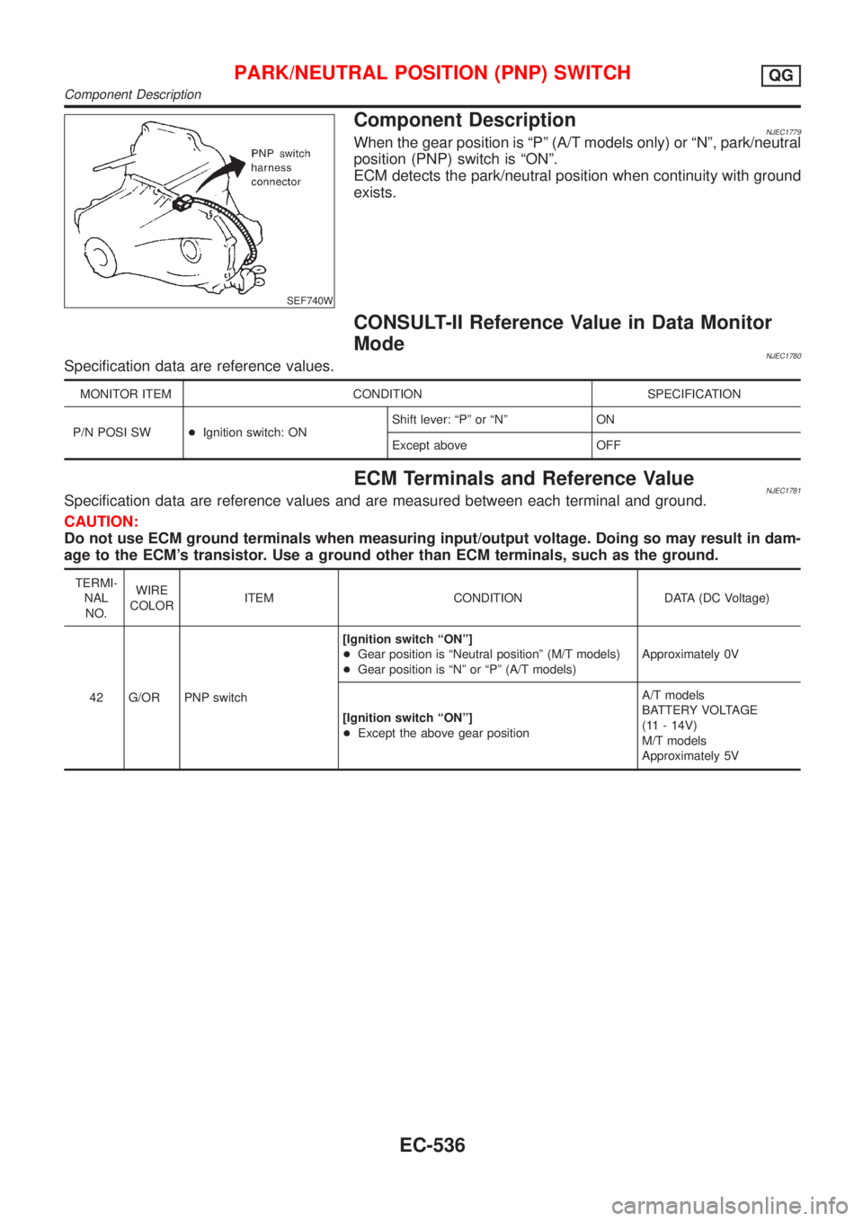
SEF740W
Component DescriptionNJEC1779When the gear position is ªPº (A/T models only) or ªNº, park/neutral
position (PNP) switch is ªONº.
ECM detects the park/neutral position when continuity with ground
exists.
CONSULT-II Reference Value in Data Monitor
Mode
NJEC1780Specification data are reference values.
MONITOR ITEM CONDITION SPECIFICATION
P/N POSI SW+Ignition switch: ONShift lever: ªPº or ªNº ON
Except above OFF
ECM Terminals and Reference ValueNJEC1781Specification data are reference values and are measured between each terminal and ground.
CAUTION:
Do not use ECM ground terminals when measuring input/output voltage. Doing so may result in dam-
age to the ECM's transistor. Use a ground other than ECM terminals, such as the ground.
TERMI-
NAL
NO.WIRE
COLORITEM CONDITION DATA (DC Voltage)
42 G/OR PNP switch[Ignition switch ªONº]
+Gear position is ªNeutral positionº (M/T models)
+Gear position is ªNº or ªPº (A/T models)Approximately 0V
[Ignition switch ªONº]
+Except the above gear positionA/T models
BATTERY VOLTAGE
(11 - 14V)
M/T models
Approximately 5V
PARK/NEUTRAL POSITION (PNP) SWITCHQG
Component Description
EC-536
Page 1262 of 2898
Diagnostic ProcedureNJEC1783
1 INSPECTION START
Do you have CONSULT-II?
YesorNo
Ye s©GO TO 2.
No©GO TO 3.
2 CHECK OVERALL FUNCTION
With CONSULT-II
1. Turn ignition switch ªONº.
2. Select ªP/N POSI SWº in ªDATA MONITORº mode with CONSULT-II.
3. Check the ªP/N POSI SWº signal under the following conditions.
SEF836Z
OK or NG
OK©INSPECTION END
NG©GO TO 4.
3 CHECK OVERALL FUNCTION
Without CONSULT-II
1. Turn ignition switch ªONº.
2. Check voltage between ECM terminal 42 and ground under the following conditions.
SEF837Z
OK or NG
OK©INSPECTION END
NG©GO TO 4.
PARK/NEUTRAL POSITION (PNP) SWITCHQG
Diagnostic Procedure
EC-538
Page 1263 of 2898

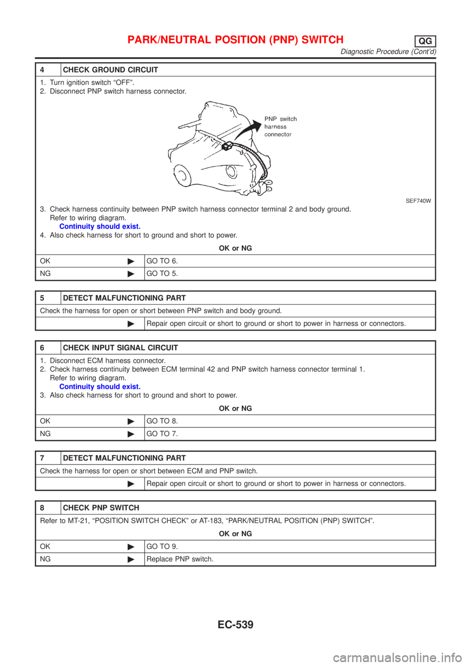
4 CHECK GROUND CIRCUIT
1. Turn ignition switch ªOFFº.
2. Disconnect PNP switch harness connector.
SEF740W
3. Check harness continuity between PNP switch harness connector terminal 2 and body ground.
Refer to wiring diagram.
Continuity should exist.
4. Also check harness for short to ground and short to power.
OK or NG
OK©GO TO 6.
NG©GO TO 5.
5 DETECT MALFUNCTIONING PART
Check the harness for open or short between PNP switch and body ground.
©Repair open circuit or short to ground or short to power in harness or connectors.
6 CHECK INPUT SIGNAL CIRCUIT
1. Disconnect ECM harness connector.
2. Check harness continuity between ECM terminal 42 and PNP switch harness connector terminal 1.
Refer to wiring diagram.
Continuity should exist.
3. Also check harness for short to ground and short to power.
OK or NG
OK©GO TO 8.
NG©GO TO 7.
7 DETECT MALFUNCTIONING PART
Check the harness for open or short between ECM and PNP switch.
©Repair open circuit or short to ground or short to power in harness or connectors.
8 CHECK PNP SWITCH
Refer to MT-21, ªPOSITION SWITCH CHECKº or AT-183, ªPARK/NEUTRAL POSITION (PNP) SWITCHº.
OK or NG
OK©GO TO 9.
NG©Replace PNP switch.
PARK/NEUTRAL POSITION (PNP) SWITCHQG
Diagnostic Procedure (Cont'd)
EC-539
Page 1269 of 2898

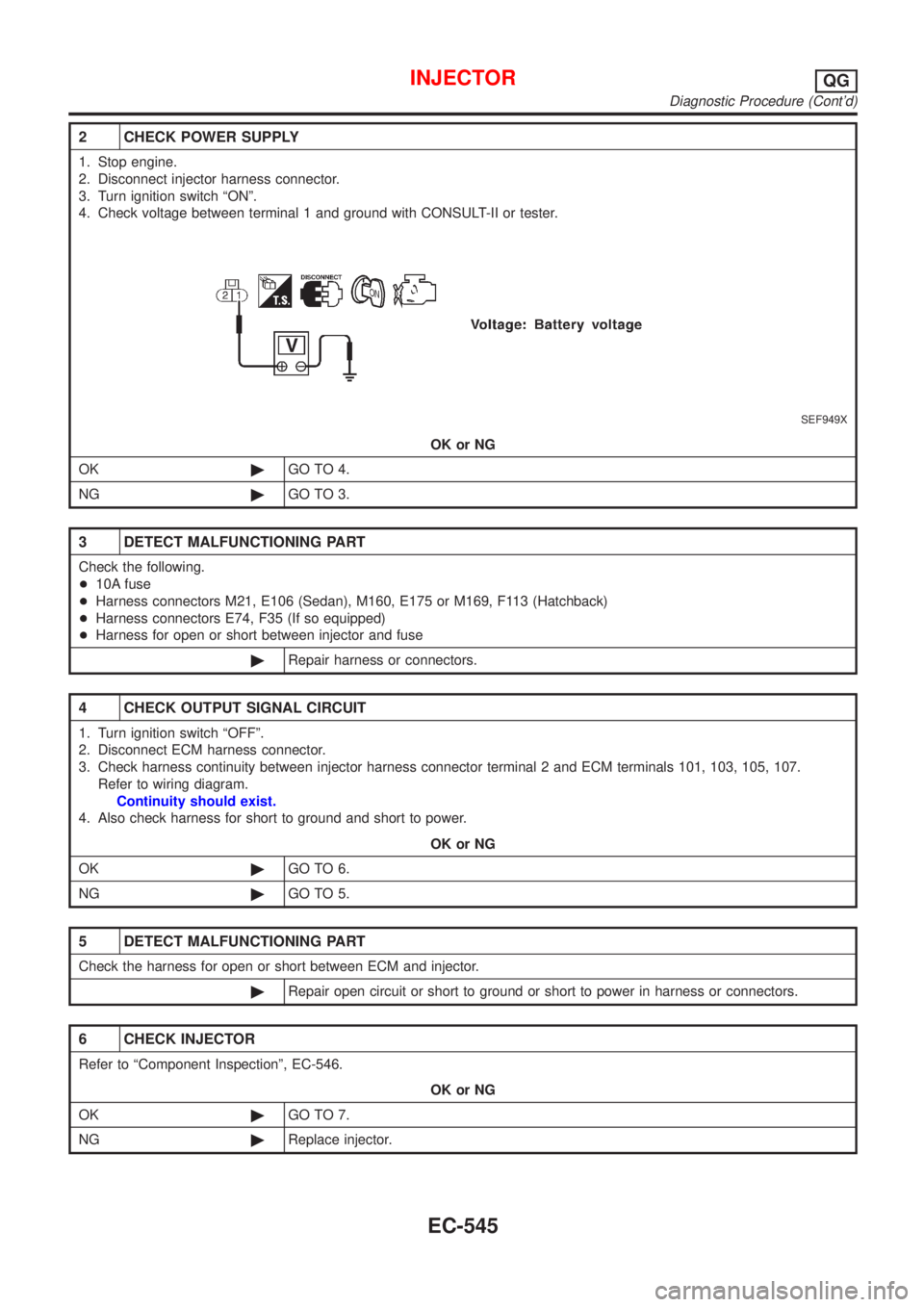
2 CHECK POWER SUPPLY
1. Stop engine.
2. Disconnect injector harness connector.
3. Turn ignition switch ªONº.
4. Check voltage between terminal 1 and ground with CONSULT-II or tester.
SEF949X
OK or NG
OK©GO TO 4.
NG©GO TO 3.
3 DETECT MALFUNCTIONING PART
Check the following.
+10A fuse
+Harness connectors M21, E106 (Sedan), M160, E175 or M169, F113 (Hatchback)
+Harness connectors E74, F35 (If so equipped)
+Harness for open or short between injector and fuse
©Repair harness or connectors.
4 CHECK OUTPUT SIGNAL CIRCUIT
1. Turn ignition switch ªOFFº.
2. Disconnect ECM harness connector.
3. Check harness continuity between injector harness connector terminal 2 and ECM terminals 101, 103, 105, 107.
Refer to wiring diagram.
Continuity should exist.
4. Also check harness for short to ground and short to power.
OK or NG
OK©GO TO 6.
NG©GO TO 5.
5 DETECT MALFUNCTIONING PART
Check the harness for open or short between ECM and injector.
©Repair open circuit or short to ground or short to power in harness or connectors.
6 CHECK INJECTOR
Refer to ªComponent Inspectionº, EC-546.
OK or NG
OK©GO TO 7.
NG©Replace injector.
INJECTORQG
Diagnostic Procedure (Cont'd)
EC-545
Page 1271 of 2898

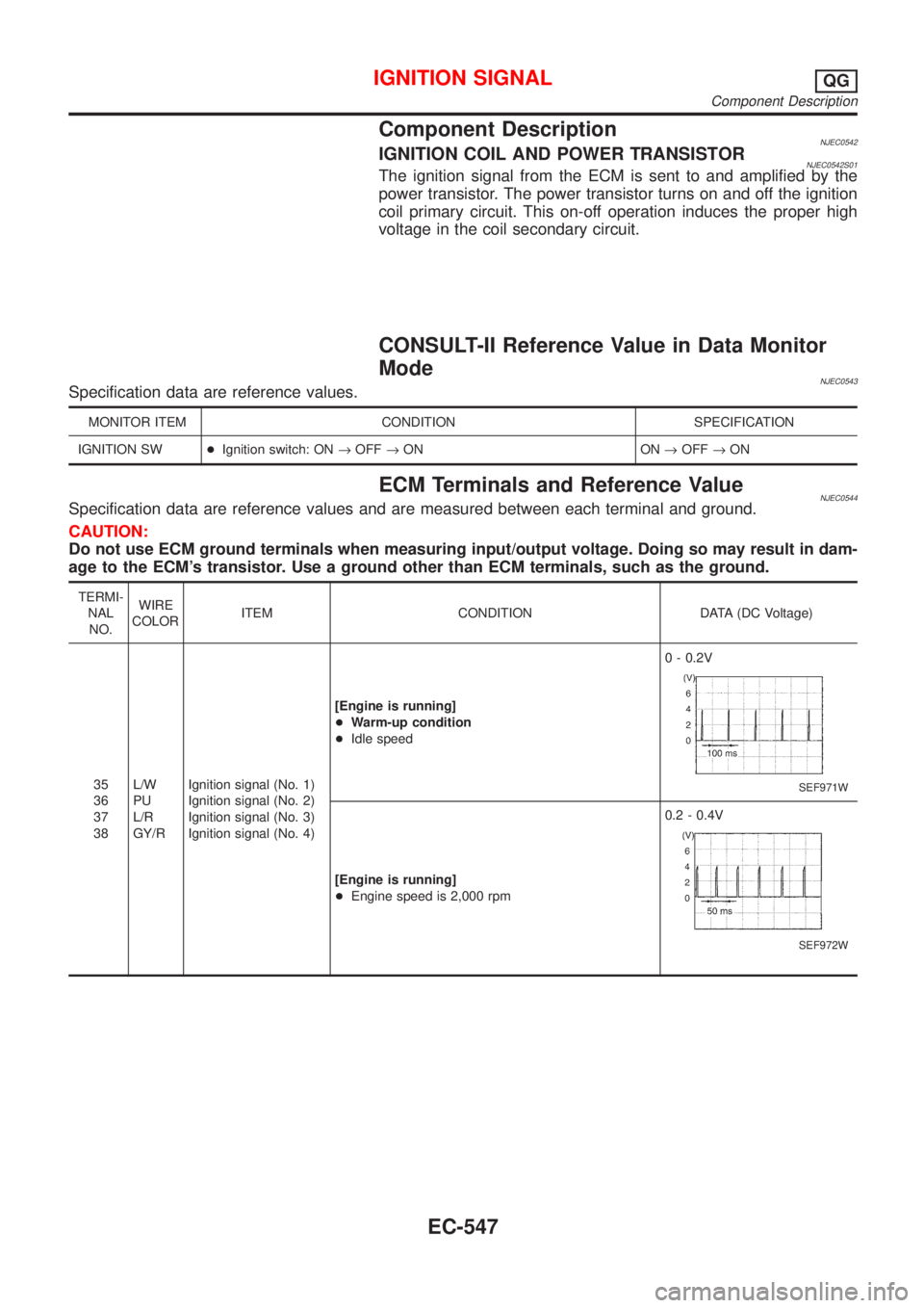
Component DescriptionNJEC0542IGNITION COIL AND POWER TRANSISTORNJEC0542S01The ignition signal from the ECM is sent to and amplified by the
power transistor. The power transistor turns on and off the ignition
coil primary circuit. This on-off operation induces the proper high
voltage in the coil secondary circuit.
CONSULT-II Reference Value in Data Monitor
Mode
NJEC0543Specification data are reference values.
MONITOR ITEM CONDITION SPECIFICATION
IGNITION SW+Ignition switch: ON®OFF®ON ON®OFF®ON
ECM Terminals and Reference ValueNJEC0544Specification data are reference values and are measured between each terminal and ground.
CAUTION:
Do not use ECM ground terminals when measuring input/output voltage. Doing so may result in dam-
age to the ECM's transistor. Use a ground other than ECM terminals, such as the ground.
TERMI-
NAL
NO.WIRE
COLORITEM CONDITION DATA (DC Voltage)
35
36
37
38L/W
PU
L/R
GY/RIgnition signal (No. 1)
Ignition signal (No. 2)
Ignition signal (No. 3)
Ignition signal (No. 4)[Engine is running]
+Warm-up condition
+Idle speed0 - 0.2V
SEF971W
[Engine is running]
+Engine speed is 2,000 rpm0.2 - 0.4V
SEF972W
IGNITION SIGNALQG
Component Description
EC-547
Page 1272 of 2898
Wiring DiagramNJEC1784SEDAN MODELS AND HATCHBACK MODELS WITH ECM IN ENGINE COMPARTMENTNJEC1784S01
HEC964
IGNITION SIGNALQG
Wiring Diagram
EC-548
Page 1273 of 2898
HATCHBACK MODELS WITH ECM IN CABINNJEC1784S02
HEC979
IGNITION SIGNALQG
Wiring Diagram (Cont'd)
EC-549
Page 1274 of 2898
HEC965
IGNITION SIGNALQG
Wiring Diagram (Cont'd)
EC-550