Page 1300 of 2898
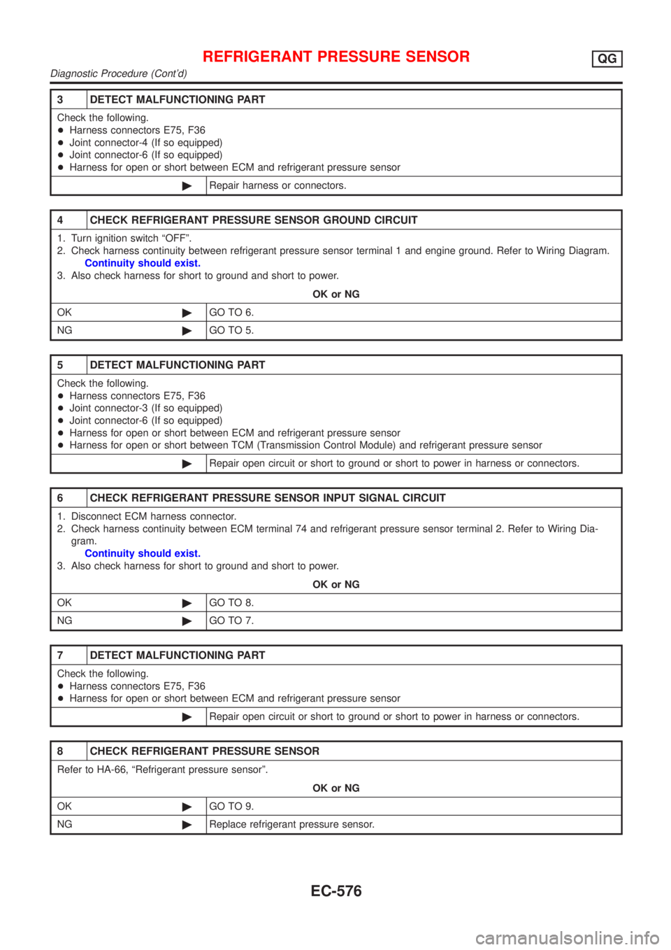
3 DETECT MALFUNCTIONING PART
Check the following.
+Harness connectors E75, F36
+Joint connector-4 (If so equipped)
+Joint connector-6 (If so equipped)
+Harness for open or short between ECM and refrigerant pressure sensor
©Repair harness or connectors.
4 CHECK REFRIGERANT PRESSURE SENSOR GROUND CIRCUIT
1. Turn ignition switch ªOFFº.
2. Check harness continuity between refrigerant pressure sensor terminal 1 and engine ground. Refer to Wiring Diagram.
Continuity should exist.
3. Also check harness for short to ground and short to power.
OK or NG
OK©GO TO 6.
NG©GO TO 5.
5 DETECT MALFUNCTIONING PART
Check the following.
+Harness connectors E75, F36
+Joint connector-3 (If so equipped)
+Joint connector-6 (If so equipped)
+Harness for open or short between ECM and refrigerant pressure sensor
+Harness for open or short between TCM (Transmission Control Module) and refrigerant pressure sensor
©Repair open circuit or short to ground or short to power in harness or connectors.
6 CHECK REFRIGERANT PRESSURE SENSOR INPUT SIGNAL CIRCUIT
1. Disconnect ECM harness connector.
2. Check harness continuity between ECM terminal 74 and refrigerant pressure sensor terminal 2. Refer to Wiring Dia-
gram.
Continuity should exist.
3. Also check harness for short to ground and short to power.
OK or NG
OK©GO TO 8.
NG©GO TO 7.
7 DETECT MALFUNCTIONING PART
Check the following.
+Harness connectors E75, F36
+Harness for open or short between ECM and refrigerant pressure sensor
©Repair open circuit or short to ground or short to power in harness or connectors.
8 CHECK REFRIGERANT PRESSURE SENSOR
Refer to HA-66, ªRefrigerant pressure sensorº.
OK or NG
OK©GO TO 9.
NG©Replace refrigerant pressure sensor.
REFRIGERANT PRESSURE SENSORQG
Diagnostic Procedure (Cont'd)
EC-576
Page 1302 of 2898
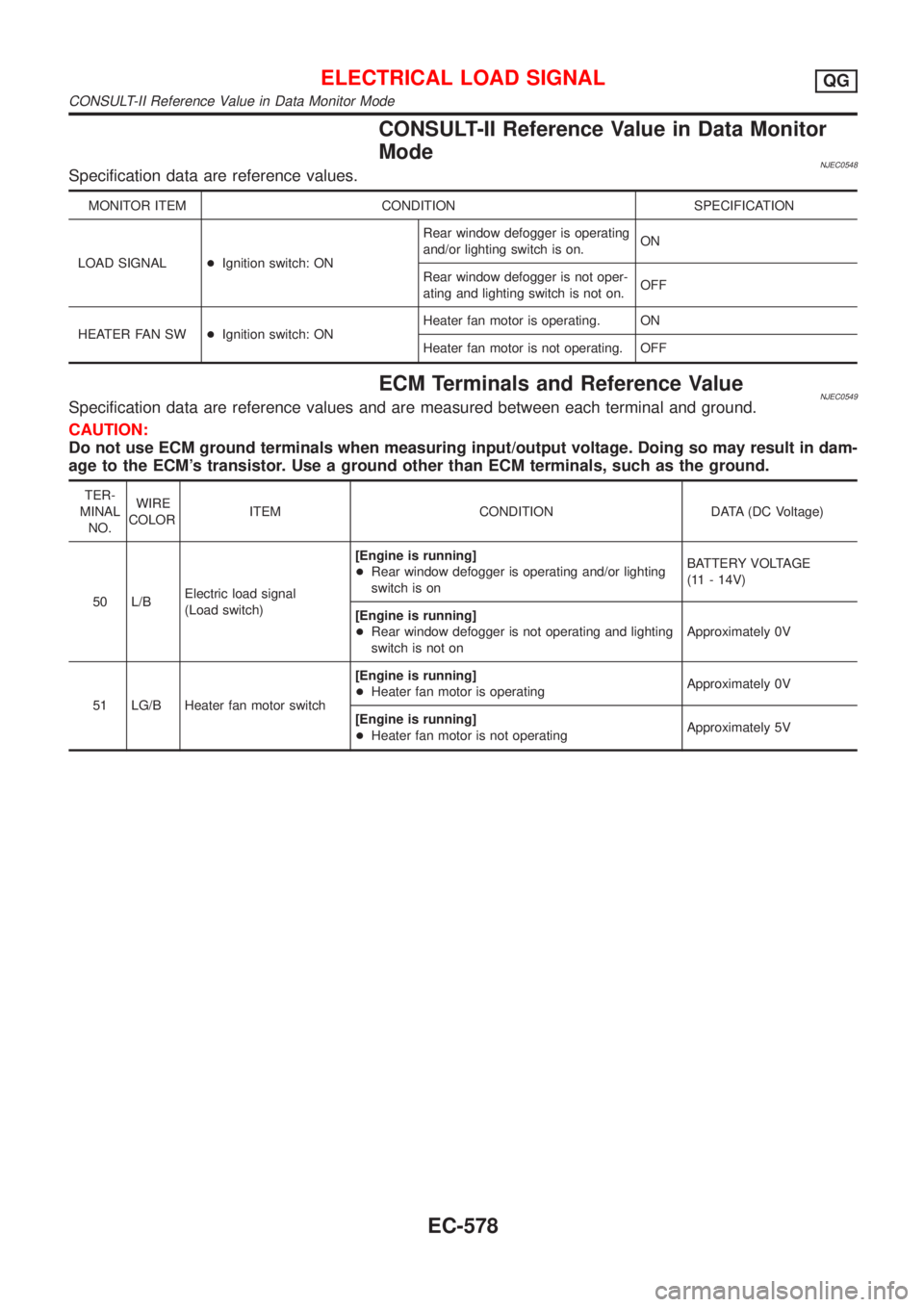
CONSULT-II Reference Value in Data Monitor
Mode
NJEC0548Specification data are reference values.
MONITOR ITEM CONDITION SPECIFICATION
LOAD SIGNAL+Ignition switch: ONRear window defogger is operating
and/or lighting switch is on.ON
Rear window defogger is not oper-
ating and lighting switch is not on.OFF
HEATER FAN SW+Ignition switch: ONHeater fan motor is operating. ON
Heater fan motor is not operating. OFF
ECM Terminals and Reference ValueNJEC0549Specification data are reference values and are measured between each terminal and ground.
CAUTION:
Do not use ECM ground terminals when measuring input/output voltage. Doing so may result in dam-
age to the ECM's transistor. Use a ground other than ECM terminals, such as the ground.
TER-
MINAL
NO.WIRE
COLORITEM CONDITION DATA (DC Voltage)
50 L/BElectric load signal
(Load switch)[Engine is running]
+Rear window defogger is operating and/or lighting
switch is onBATTERY VOLTAGE
(11 - 14V)
[Engine is running]
+Rear window defogger is not operating and lighting
switch is not onApproximately 0V
51 LG/B Heater fan motor switch[Engine is running]
+Heater fan motor is operatingApproximately 0V
[Engine is running]
+Heater fan motor is not operatingApproximately 5V
ELECTRICAL LOAD SIGNALQG
CONSULT-II Reference Value in Data Monitor Mode
EC-578
Page 1307 of 2898
Diagnostic Procedure Ð Load Signal ÐNJEC0584
1 INSPECTION START
Do you have CONSULT-II?
YesorNo
Ye s©GO TO 2.
No©GO TO 4.
2 CHECK LOAD SIGNAL CIRCUIT OVERALL FUNCTION-I
With CONSULT-II
1. Turn ignition switch ªONº.
2. Check ªLOAD SIGNALº in ªDATA MONITORº mode with CONSULT-II under the following conditions.
SEF954X
OK or NG
OK©GO TO 3.
NG©GO TO 6.
3 CHECK LOAD SIGNAL CIRCUIT OVERALL FUNCTION-II
With CONSULT-II
1. Turn ignition switch ªONº.
2. Check ªLOAD SIGNALº in ªDATA MONITORº mode with CONSULT-II under the following conditions.
SEF955X
OK or NG
OK©INSPECTION END
NG©GO TO 14.
ELECTRICAL LOAD SIGNALQG
Diagnostic Procedure Ð Load Signal Ð
EC-583
Page 1308 of 2898
4 CHECK LOAD SIGNAL CIRCUIT OVERALL FUNCTION-I
Without CONSULT-II
1. Turn ignition switch ªONº.
2. Check voltage between ECM terminal 50 and ground under the following conditions.
SEF956X
OK or NG
OK©GO TO 5.
NG©GO TO 6.
5 CHECK LOAD SIGNAL CIRCUIT OVERALL FUNCTION-II
Without CONSULT-II
1. Turn ignition switch ªONº.
2. Check voltage between ECM terminal 50 and ground under the following conditions.
SEF957X
OK or NG
OK©INSPECTION END
NG©GO TO 15.
6 CHECK REAR WINDOW DEFOGGER FUNCTION
1. Start engine.
2. Turn ªONº the rear window defogger switch.
3. Check the rear windshield. Is the rear windshield heated up?
YesorNo
Yes (Sedan)©GO TO 7.
Yes (Hatchback)©GO TO 12.
No©Refer to EL-240, ªRear Window Defoggerº.
ELECTRICAL LOAD SIGNALQG
Diagnostic Procedure Ð Load Signal Ð (Cont'd)
EC-584
Page 1317 of 2898
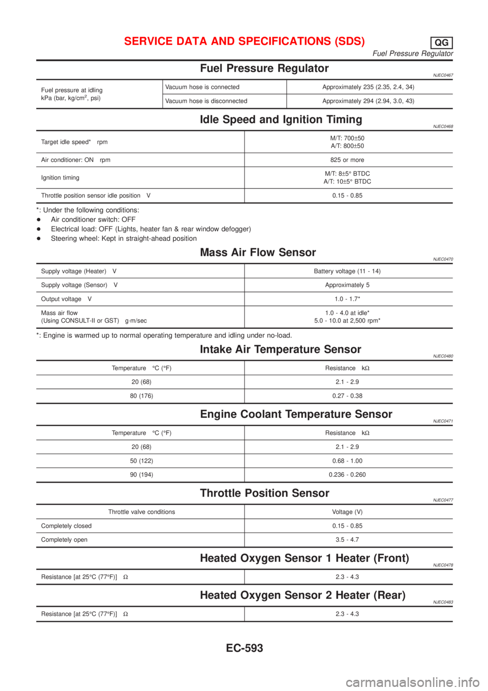
Fuel Pressure RegulatorNJEC0467
Fuel pressure at idling
kPa (bar, kg/cm2, psi)Vacuum hose is connected Approximately 235 (2.35, 2.4, 34)
Vacuum hose is disconnected Approximately 294 (2.94, 3.0, 43)
Idle Speed and Ignition TimingNJEC0468
Target idle speed* rpmM/T: 700±50
A/T: 800±50
Air conditioner: ON rpm825 or more
Ignition timingM/T: 8±5É BTDC
A/T: 10±5É BTDC
Throttle position sensor idle position V 0.15 - 0.85
*: Under the following conditions:
+Air conditioner switch: OFF
+Electrical load: OFF (Lights, heater fan & rear window defogger)
+Steering wheel: Kept in straight-ahead position
Mass Air Flow SensorNJEC0470
Supply voltage (Heater) VBattery voltage (11 - 14)
Supply voltage (Sensor) VApproximately 5
Output voltage V1.0 - 1.7*
Mass air flow
(Using CONSULT-II or GST) g´m/sec1.0 - 4.0 at idle*
5.0 - 10.0 at 2,500 rpm*
*: Engine is warmed up to normal operating temperature and idling under no-load.
Intake Air Temperature SensorNJEC0480
Temperature ÉC (ÉF) Resistance kW
20 (68) 2.1 - 2.9
80 (176) 0.27 - 0.38
Engine Coolant Temperature SensorNJEC0471
Temperature ÉC (ÉF) Resistance kW
20 (68) 2.1 - 2.9
50 (122) 0.68 - 1.00
90 (194) 0.236 - 0.260
Throttle Position SensorNJEC0477
Throttle valve conditions Voltage (V)
Completely closed0.15 - 0.85
Completely open3.5 - 4.7
Heated Oxygen Sensor 1 Heater (Front)NJEC0478
Resistance [at 25ÉC (77ÉF)]W2.3 - 4.3
Heated Oxygen Sensor 2 Heater (Rear)NJEC0483
Resistance [at 25ÉC (77ÉF)]W2.3 - 4.3
SERVICE DATA AND SPECIFICATIONS (SDS)QG
Fuel Pressure Regulator
EC-593
Page 1318 of 2898
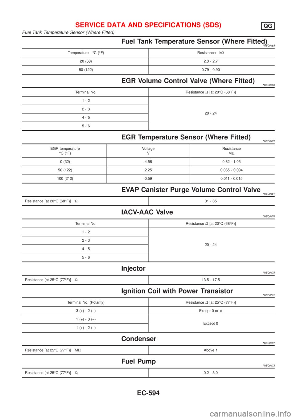
Fuel Tank Temperature Sensor (Where Fitted)NJEC0485
Temperature ÉC (ÉF) Resistance kW
20 (68) 2.3 - 2.7
50 (122) 0.79 - 0.90
EGR Volume Control Valve (Where Fitted)NJEC0560
Terminal No. ResistanceW[at 20ÉC (68ÉF)]
1-2
20-24 2-3
4-5
5-6
EGR Temperature Sensor (Where Fitted)NJEC0472
EGR temperature
ÉC (ÉF)Voltage
VResistance
MW
0 (32) 4.56 0.62 - 1.05
50 (122) 2.25 0.065 - 0.094
100 (212) 0.59 0.011 - 0.015
EVAP Canister Purge Volume Control ValveNJEC0481
Resistance [at 20ÉC (68ÉF)]W31-35
IACV-AAC ValveNJEC0474
Terminal No. ResistanceW[at 20ÉC (68ÉF)]
1-2
20-24 2-3
4-5
5-6
InjectorNJEC0475
Resistance [at 25ÉC (77ÉF)]W13.5 - 17.5
Ignition Coil with Power TransistorNJEC0561
Terminal No. (Polarity) ResistanceW[at 25ÉC (77ÉF)]
3 (+) - 2 (þ) Except 0 or¥
1 (+) - 3 (þ)
Except 0
1 (+) - 2 (þ)
CondenserNJEC0587
Resistance [at 25ÉC (77ÉF)] MWAbove 1
Fuel PumpNJEC0473
Resistance [at 25ÉC (77ÉF)]W0.2 - 5.0
SERVICE DATA AND SPECIFICATIONS (SDS)QG
Fuel Tank Temperature Sensor (Where Fitted)
EC-594
Page 1324 of 2898
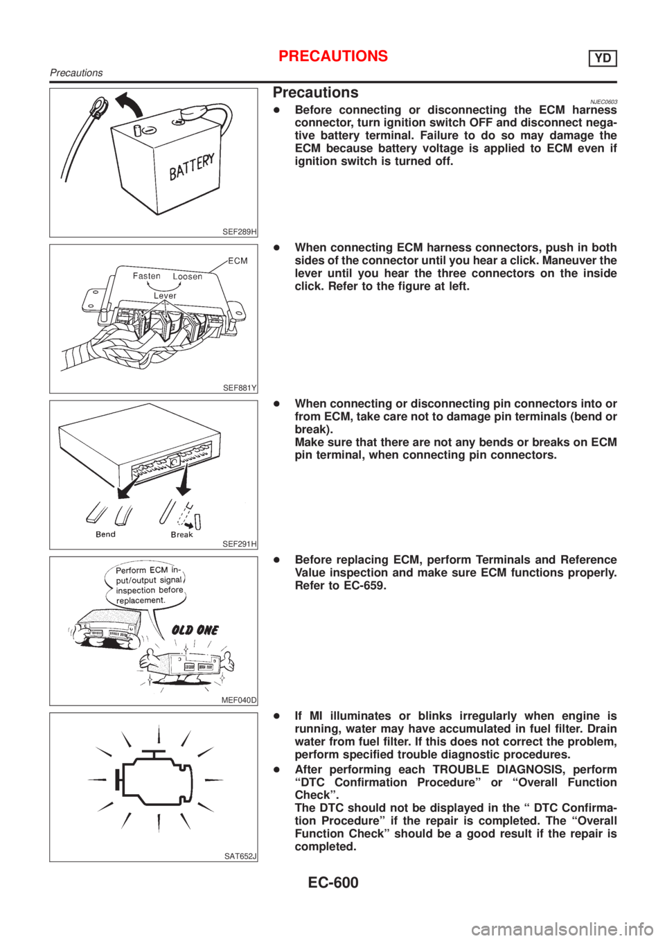
SEF289H
PrecautionsNJEC0603+Before connecting or disconnecting the ECM harness
connector, turn ignition switch OFF and disconnect nega-
tive battery terminal. Failure to do so may damage the
ECM because battery voltage is applied to ECM even if
ignition switch is turned off.
SEF881Y
+When connecting ECM harness connectors, push in both
sides of the connector until you hear a click. Maneuver the
lever until you hear the three connectors on the inside
click. Refer to the figure at left.
SEF291H
+When connecting or disconnecting pin connectors into or
from ECM, take care not to damage pin terminals (bend or
break).
Make sure that there are not any bends or breaks on ECM
pin terminal, when connecting pin connectors.
MEF040D
+Before replacing ECM, perform Terminals and Reference
Value inspection and make sure ECM functions properly.
Refer to EC-659.
SAT652J
+If MI illuminates or blinks irregularly when engine is
running, water may have accumulated in fuel filter. Drain
water from fuel filter. If this does not correct the problem,
perform specified trouble diagnostic procedures.
+After performing each TROUBLE DIAGNOSIS, perform
ªDTC Confirmation Procedureº or ªOverall Function
Checkº.
The DTC should not be displayed in the ª DTC Confirma-
tion Procedureº if the repair is completed. The ªOverall
Function Checkº should be a good result if the repair is
completed.
PRECAUTIONSYD
Precautions
EC-600
Page 1333 of 2898
System ChartNJEC0611
Input (Sensor) ECM Function Output (Actuator)
+Electronic control fuel injection pump
+Crankshaft position sensor (TDC)
+Engine coolant temperature sensor
+Accelerator position sensor
+Accelerator position switch
+Park/Neutral position (PNP) switch*
+Ignition switch
+Battery voltage
+Vehicle speed sensor
+Air conditioner switch
+Mass air flow sensor
+Stop lamp switchFuel injection controlElectronic control fuel injection
pump
Fuel injection timing controlElectronic control fuel injection
pump
Fuel cut controlElectronic control fuel injection
pump
Glow control system Glow relay & glow lamp
On board diagnostic system MI (On the instrument panel)
EGR volume control EGR volume control valve
Cooling fan control Cooling fan relay
Air conditioning cut control Air conditioner relay
*: If so equipped
ENGINE AND EMISSION CONTROL OVERALL SYSTEMYD
System Chart
EC-609