Page 1190 of 2898
3 RETIGHTEN GROUND SCREWS
1. Turn ignition switch ªOFFº.
2. Loosen and retighten engine ground screws.
JEF104Y
©GO TO 4.
4 CHECK INPUT SIGNAL CIRCUIT
1. Turn ignition switch ªOFFº.
2. Disconnect heated oxygen sensor 2 (rear) harness connector and ECM harness connector.
SEF160Z
3. Check harness continuity between ECM terminal 63 and heated oxygen sensor 2 (rear) harness connector terminal 1.
Refer to wiring diagram.
Continuity should exist.
4. Check harness continuity between ECM terminal 63 [or heated oxygen sensor 2 (rear) harness connector terminal 1]
and ground.
Continuity should not exist.
5. Also check harness for short to ground and short to power.
OK or NG
OK©GO TO 6.
NG©GO TO 5.
5 DETECT MALFUNCTIONING PART
Check the harness for open or short between heated oxygen sensor 2 (rear) and ECM.
©Repair open circuit or short to ground or short to power in harness or connectors.
HEATED OXYGEN SENSOR 2 (REAR)QG
Diagnostic Procedure (Cont'd)
EC-466
Page 1193 of 2898
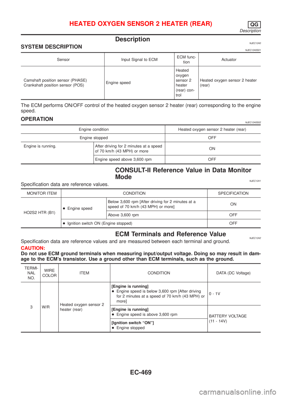
DescriptionNJEC1240SYSTEM DESCRIPTIONNJEC1240S01
Sensor Input Signal to ECMECM func-
tionActuator
Camshaft position sensor (PHASE)
Crankshaft position sensor (POS)Engine speedHeated
oxygen
sensor 2
heater
(rear) con-
trolHeated oxygen sensor 2 heater
(rear)
The ECM performs ON/OFF control of the heated oxygen sensor 2 heater (rear) corresponding to the engine
speed.
OPERATIONNJEC1240S02
Engine condition Heated oxygen sensor 2 heater (rear)
Engine stopped OFF
Engine is running. After driving for 2 minutes at a speed
of 70 km/h (43 MPH) or moreON
Engine speed above 3,600 rpm OFF
CONSULT-II Reference Value in Data Monitor
Mode
NJEC1241Specification data are reference values.
MONITOR ITEM CONDITION SPECIFICATION
HO2S2 HTR (B1)+Engine speedBelow 3,600 rpm [After driving for 2 minutes at a
speed of 70 km/h (43 MPH) or more]ON
Above 3,600 rpm OFF
+Ignition switch ON (Engine stopped) OFF
ECM Terminals and Reference ValueNJEC1242Specification data are reference values and are measured between each terminal and ground.
CAUTION:
Do not use ECM ground terminals when measuring input/output voltage. Doing so may result in dam-
age to the ECM's transistor. Use a ground other than ECM terminals, such as the ground.
TERMI-
NAL
NO.WIRE
COLORITEM CONDITION DATA (DC Voltage)
3 W/RHeated oxygen sensor 2
heater (rear)[Engine is running]
+Engine speed is below 3,600 rpm [After driving
for 2 minutes at a speed of 70 km/h (43 MPH) or
more]0-1V
[Engine is running]
+Engine speed is above 3,600 rpm
BATTERY VOLTAGE
(11 - 14V)
[Ignition switch ªONº]
+Engine stopped
HEATED OXYGEN SENSOR 2 HEATER (REAR)QG
Description
EC-469
Page 1196 of 2898
Diagnostic ProcedureNJEC1246
1 CHECK OVERALL FUNCTION
Without CONSULT-II
1. Start engine and drive the vehicle at over 70 km/h (43 MPH) for 2 consecutive minutes.
2. Stop vehicle and keep the engine running.
3. Set the voltmeter probe between ECM terminals 3 [HO2S2 HTR (B1) signal] and ground.
4. Check the voltage under the following conditions.
SEF241Z
OK or NG
OK©INSPECTION END
NG©GO TO 2.
2 CHECK POWER SUPPLY
1. Turn ignition switch ªOFFº.
2. Disconnect heated oxygen sensor 2 (rear) harness connector.
SEF160Z
3. Turn ignition switch ªONº.
4. Check voltage between terminal 2 and ground.
SEF218W
OK or NG
OK©GO TO 4.
NG©GO TO 3.
HEATED OXYGEN SENSOR 2 HEATER (REAR)QG
Diagnostic Procedure
EC-472
Page 1197 of 2898
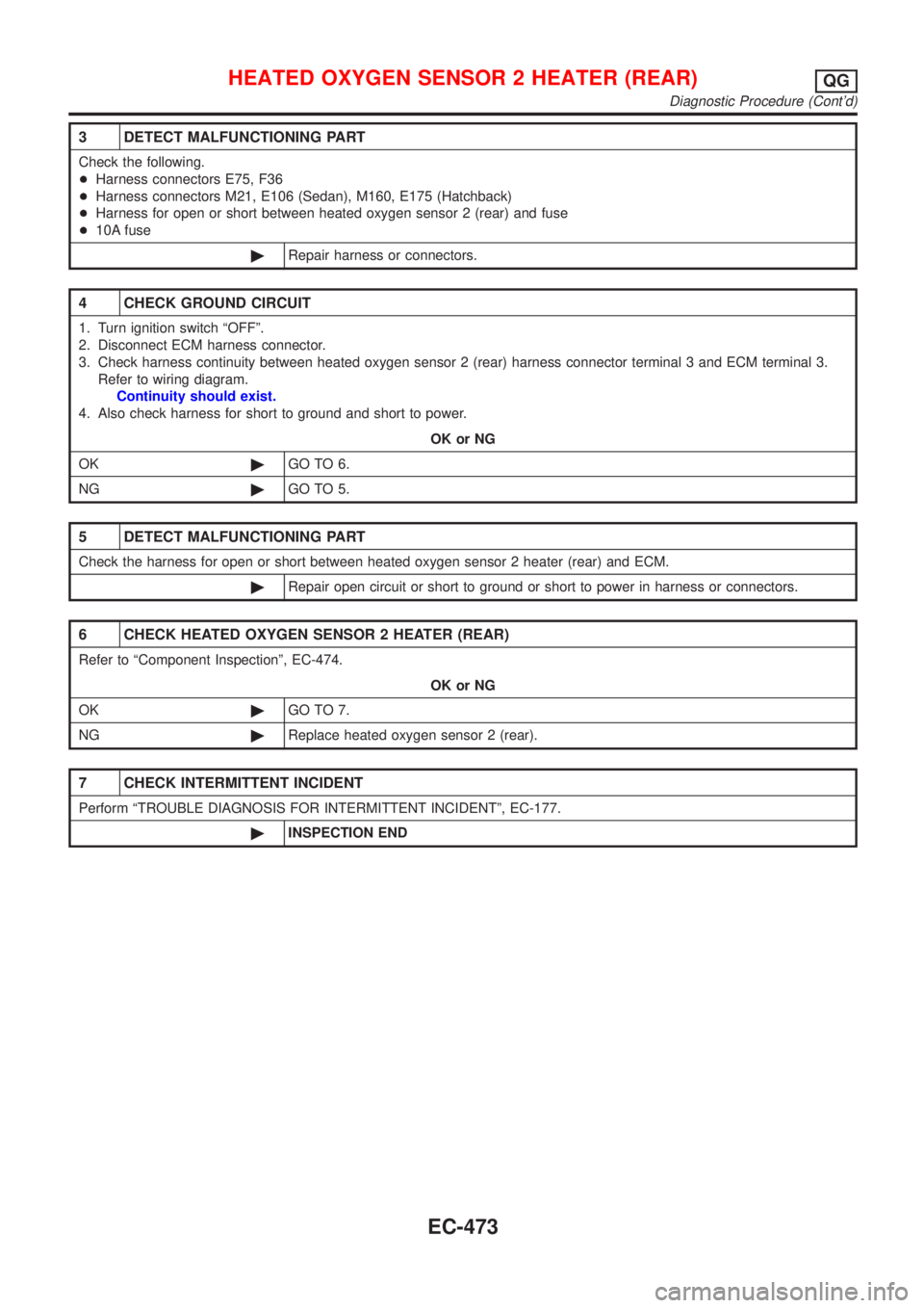
3 DETECT MALFUNCTIONING PART
Check the following.
+Harness connectors E75, F36
+Harness connectors M21, E106 (Sedan), M160, E175 (Hatchback)
+Harness for open or short between heated oxygen sensor 2 (rear) and fuse
+10A fuse
©Repair harness or connectors.
4 CHECK GROUND CIRCUIT
1. Turn ignition switch ªOFFº.
2. Disconnect ECM harness connector.
3. Check harness continuity between heated oxygen sensor 2 (rear) harness connector terminal 3 and ECM terminal 3.
Refer to wiring diagram.
Continuity should exist.
4. Also check harness for short to ground and short to power.
OK or NG
OK©GO TO 6.
NG©GO TO 5.
5 DETECT MALFUNCTIONING PART
Check the harness for open or short between heated oxygen sensor 2 heater (rear) and ECM.
©Repair open circuit or short to ground or short to power in harness or connectors.
6 CHECK HEATED OXYGEN SENSOR 2 HEATER (REAR)
Refer to ªComponent Inspectionº, EC-474.
OK or NG
OK©GO TO 7.
NG©Replace heated oxygen sensor 2 (rear).
7 CHECK INTERMITTENT INCIDENT
Perform ªTROUBLE DIAGNOSIS FOR INTERMITTENT INCIDENTº, EC-177.
©INSPECTION END
HEATED OXYGEN SENSOR 2 HEATER (REAR)QG
Diagnostic Procedure (Cont'd)
EC-473
Page 1199 of 2898
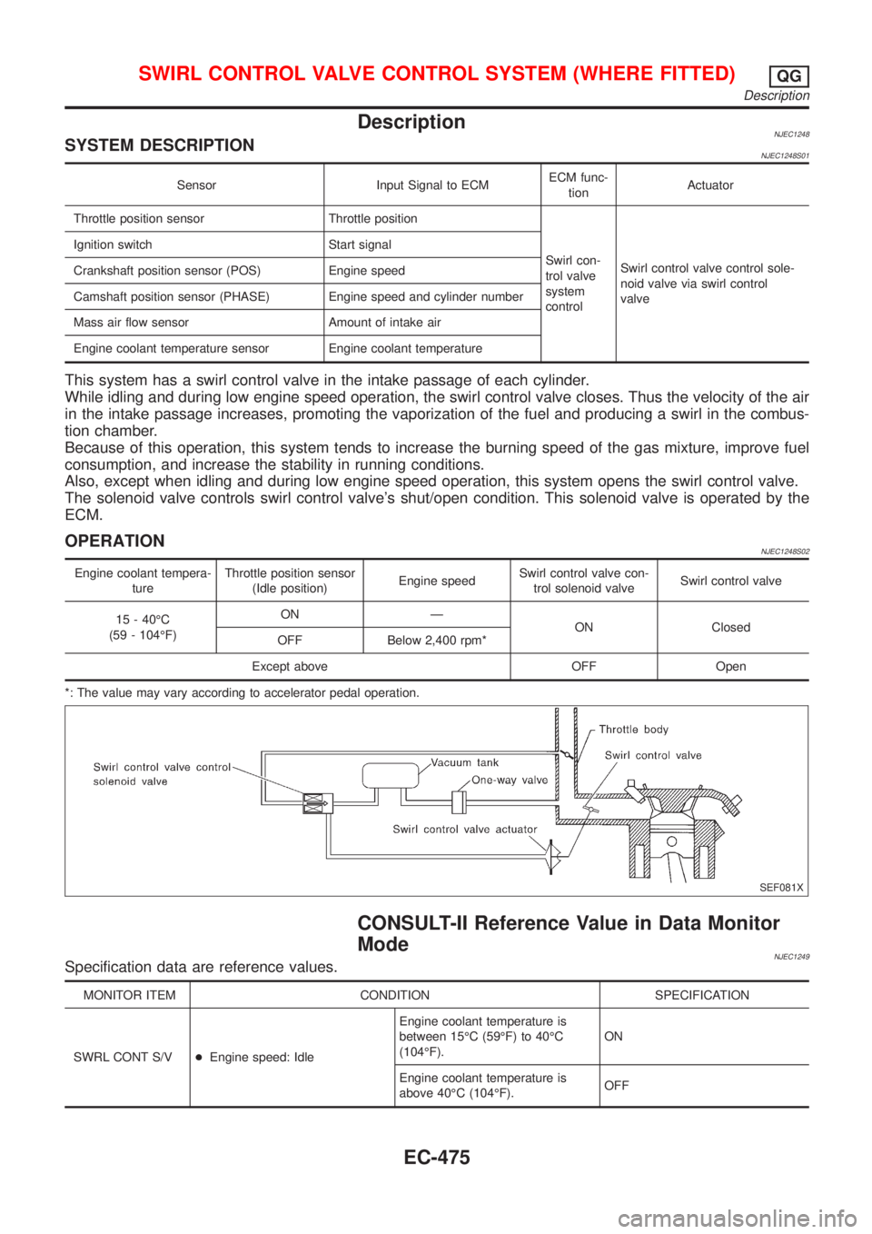
DescriptionNJEC1248SYSTEM DESCRIPTIONNJEC1248S01
Sensor Input Signal to ECMECM func-
tionActuator
Throttle position sensor Throttle position
Swirl con-
trol valve
system
controlSwirl control valve control sole-
noid valve via swirl control
valve Ignition switch Start signal
Crankshaft position sensor (POS) Engine speed
Camshaft position sensor (PHASE) Engine speed and cylinder number
Mass air flow sensor Amount of intake air
Engine coolant temperature sensor Engine coolant temperature
This system has a swirl control valve in the intake passage of each cylinder.
While idling and during low engine speed operation, the swirl control valve closes. Thus the velocity of the air
in the intake passage increases, promoting the vaporization of the fuel and producing a swirl in the combus-
tion chamber.
Because of this operation, this system tends to increase the burning speed of the gas mixture, improve fuel
consumption, and increase the stability in running conditions.
Also, except when idling and during low engine speed operation, this system opens the swirl control valve.
The solenoid valve controls swirl control valve's shut/open condition. This solenoid valve is operated by the
ECM.
OPERATIONNJEC1248S02
Engine coolant tempera-
tureThrottle position sensor
(Idle position)Engine speedSwirl control valve con-
trol solenoid valveSwirl control valve
15 - 40ÉC
(59 - 104ÉF)ON Ð
ON Closed
OFF Below 2,400 rpm*
Except above OFF Open
*: The value may vary according to accelerator pedal operation.
SEF081X
CONSULT-II Reference Value in Data Monitor
Mode
NJEC1249Specification data are reference values.
MONITOR ITEM CONDITION SPECIFICATION
SWRL CONT S/V+Engine speed: IdleEngine coolant temperature is
between 15ÉC (59ÉF) to 40ÉC
(104ÉF).ON
Engine coolant temperature is
above 40ÉC (104ÉF).OFF
SWIRL CONTROL VALVE CONTROL SYSTEM (WHERE FITTED)QG
Description
EC-475
Page 1205 of 2898
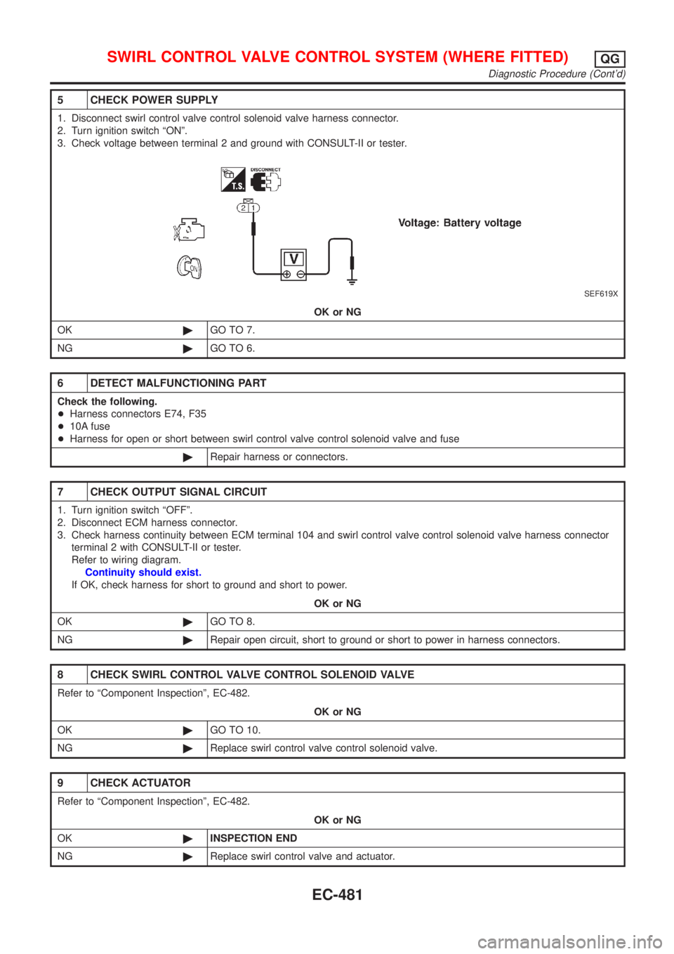
5 CHECK POWER SUPPLY
1. Disconnect swirl control valve control solenoid valve harness connector.
2. Turn ignition switch ªONº.
3. Check voltage between terminal 2 and ground with CONSULT-II or tester.
SEF619X
OK or NG
OK©GO TO 7.
NG©GO TO 6.
6 DETECT MALFUNCTIONING PART
Check the following.
+Harness connectors E74, F35
+10A fuse
+Harness for open or short between swirl control valve control solenoid valve and fuse
©Repair harness or connectors.
7 CHECK OUTPUT SIGNAL CIRCUIT
1. Turn ignition switch ªOFFº.
2. Disconnect ECM harness connector.
3. Check harness continuity between ECM terminal 104 and swirl control valve control solenoid valve harness connector
terminal 2 with CONSULT-II or tester.
Refer to wiring diagram.
Continuity should exist.
If OK, check harness for short to ground and short to power.
OK or NG
OK©GO TO 8.
NG©Repair open circuit, short to ground or short to power in harness connectors.
8 CHECK SWIRL CONTROL VALVE CONTROL SOLENOID VALVE
Refer to ªComponent Inspectionº, EC-482.
OK or NG
OK©GO TO 10.
NG©Replace swirl control valve control solenoid valve.
9 CHECK ACTUATOR
Refer to ªComponent Inspectionº, EC-482.
OK or NG
OK©INSPECTION END
NG©Replace swirl control valve and actuator.
SWIRL CONTROL VALVE CONTROL SYSTEM (WHERE FITTED)QG
Diagnostic Procedure (Cont'd)
EC-481
Page 1207 of 2898
SEF105X
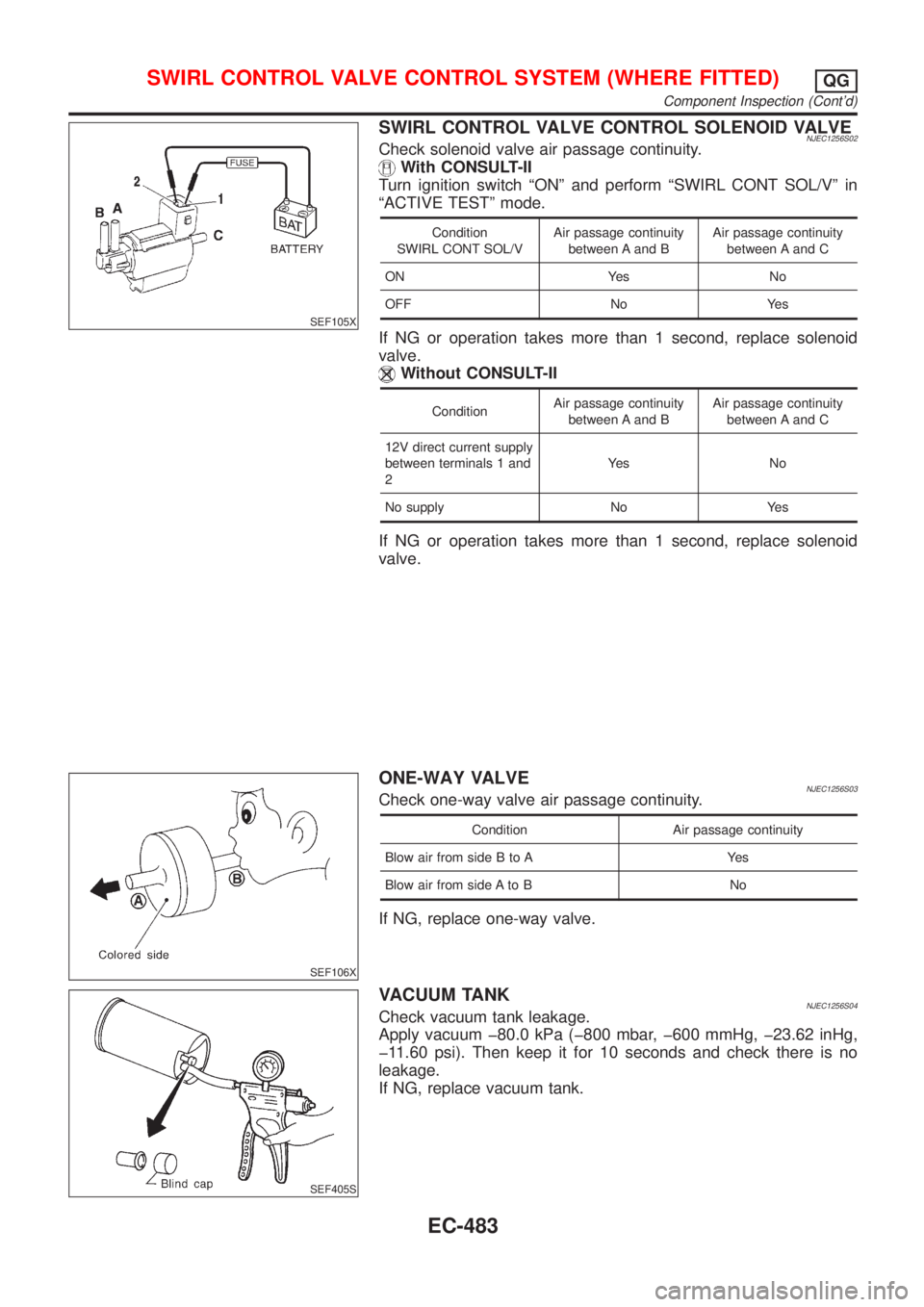
SWIRL CONTROL VALVE CONTROL SOLENOID VALVENJEC1256S02Check solenoid valve air passage continuity.
With CONSULT-II
Turn ignition switch ªONº and perform ªSWIRL CONT SOL/Vº in
ªACTIVE TESTº mode.
Condition
SWIRL CONT SOL/VAir passage continuity
between A and BAir passage continuity
between A and C
ON Yes No
OFF No Yes
If NG or operation takes more than 1 second, replace solenoid
valve.
Without CONSULT-II
ConditionAir passage continuity
between A and BAir passage continuity
between A and C
12V direct current supply
between terminals 1 and
2Ye s N o
No supply No Yes
If NG or operation takes more than 1 second, replace solenoid
valve.
SEF106X
ONE-WAY VALVENJEC1256S03Check one-way valve air passage continuity.
Condition Air passage continuity
Blow air from side B to A Yes
Blow air from side A to B No
If NG, replace one-way valve.
SEF405S
VACUUM TANKNJEC1256S04Check vacuum tank leakage.
Apply vacuum þ80.0 kPa (þ800 mbar, þ600 mmHg, þ23.62 inHg,
þ11.60 psi). Then keep it for 10 seconds and check there is no
leakage.
If NG, replace vacuum tank.
SWIRL CONTROL VALVE CONTROL SYSTEM (WHERE FITTED)QG
Component Inspection (Cont'd)
EC-483
Page 1211 of 2898
Diagnostic ProcedureNJEC1744
1 CHECK OVERALL FUNCTION
1. Start engine and let it idle.
2. Check voltage between ECM terminal 85 and ground.
SEF761Z
OK or NG
OK©INSPECTION END
NG©GO TO 2.
2 RETIGHTEN GROUND SCREWS
1. Turn ignition switch ªOFFº.
2. Loosen and retighten engine ground screws.
JEF104Y
©GO TO 3.
CRANKSHAFT POSITION SENSOR (POS)QG
Diagnostic Procedure
EC-487