Page 1212 of 2898
3 CHECK POWER SUPPLY
1. Disconnect crankshaft position sensor harness connector.
JEF835Z
2. Turn ignition switch ªONº.
3. Check voltage between terminal 3 and ground with CONSULT-II or tester.
SEF113Y
OK or NG
OK©GO TO 5.
NG©GO TO 4.
4 DETECT MALFUNCTIONING PART
Check the following.
+Joint connector-4 (If so equipped)
+Joint connector-6 (If so equipped)
+Harness for open or short between joint connector and ECM relay
+Harness for open or short between crankshaft position sensor and joint connector
+Harness for open or short between joint connector and ECM
+ECM relay
©Repair open circuit or short to ground or short to power in harness or connectors.
CRANKSHAFT POSITION SENSOR (POS)QG
Diagnostic Procedure (Cont'd)
EC-488
Page 1213 of 2898

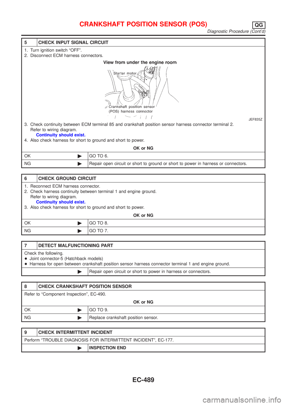
5 CHECK INPUT SIGNAL CIRCUIT
1. Turn ignition switch ªOFFº.
2. Disconnect ECM harness connectors.
JEF835Z
3. Check continuity between ECM terminal 85 and crankshaft position sensor harness connector terminal 2.
Refer to wiring diagram.
Continuity should exist.
4. Also check harness for short to ground and short to power.
OK or NG
OK©GO TO 6.
NG©Repair open circuit or short to ground or short to power in harness or connectors.
6 CHECK GROUND CIRCUIT
1. Reconnect ECM harness connector.
2. Check harness continuity between terminal 1 and engine ground.
Refer to wiring diagram.
Continuity should exist.
3. Also check harness for short to ground and short to power.
OK or NG
OK©GO TO 8.
NG©GO TO 7.
7 DETECT MALFUNCTIONING PART
Check the following.
+Joint connector-5 (Hatchback models)
+Harness for open between crankshaft position sensor harness connector terminal 1 and engine ground.
©Repair open circuit or short to power in harness or connectors.
8 CHECK CRANKSHAFT POSITION SENSOR
Refer to ªComponent Inspectionº, EC-490.
OK or NG
OK©GO TO 9.
NG©Replace crankshaft position sensor.
9 CHECK INTERMITTENT INCIDENT
Perform ªTROUBLE DIAGNOSIS FOR INTERMITTENT INCIDENTº, EC-177.
©INSPECTION END
CRANKSHAFT POSITION SENSOR (POS)QG
Diagnostic Procedure (Cont'd)
EC-489
Page 1215 of 2898

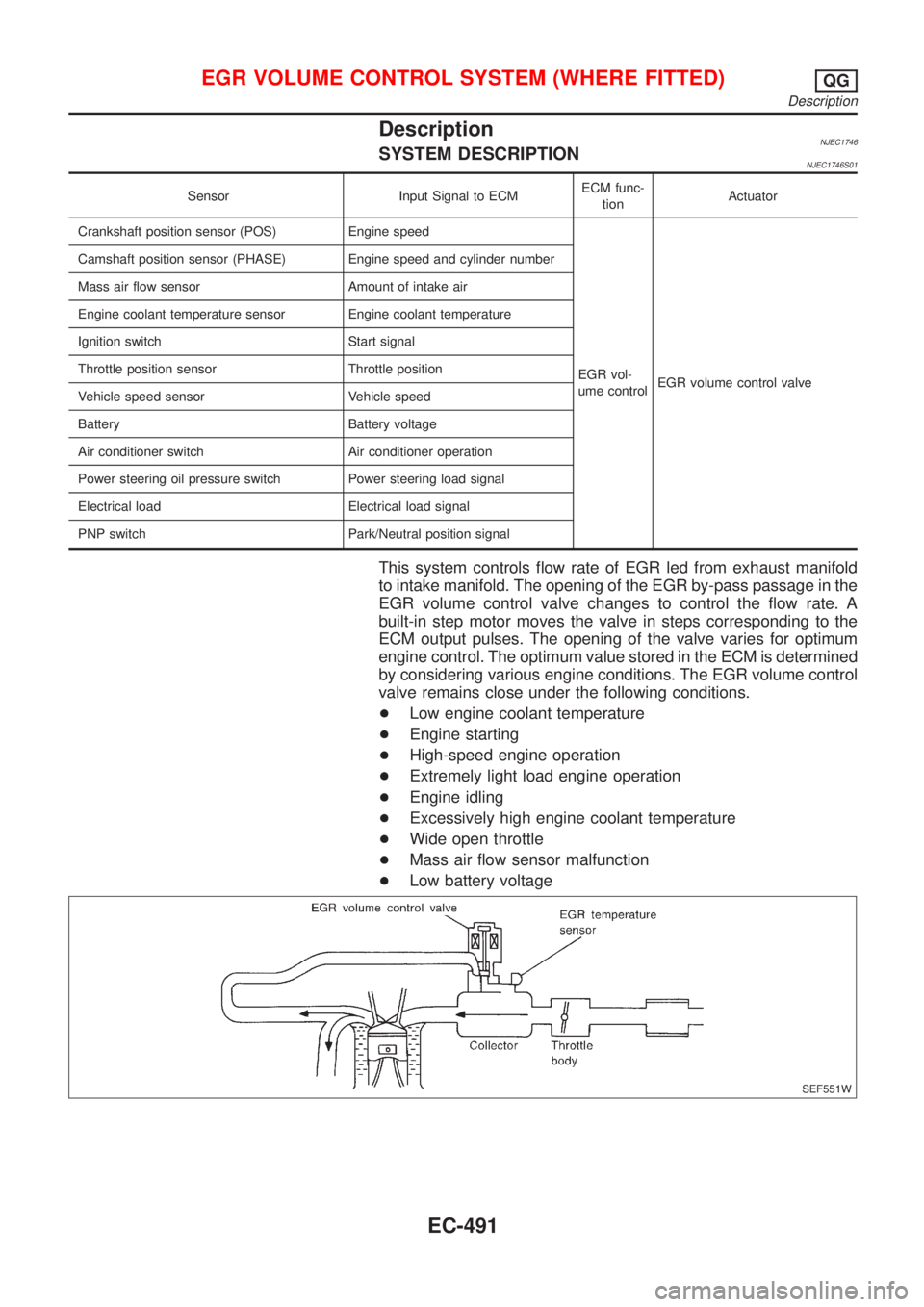
DescriptionNJEC1746SYSTEM DESCRIPTIONNJEC1746S01
Sensor Input Signal to ECMECM func-
tionActuator
Crankshaft position sensor (POS) Engine speed
EGR vol-
ume controlEGR volume control valve Camshaft position sensor (PHASE) Engine speed and cylinder number
Mass air flow sensor Amount of intake air
Engine coolant temperature sensor Engine coolant temperature
Ignition switch Start signal
Throttle position sensor Throttle position
Vehicle speed sensor Vehicle speed
Battery Battery voltage
Air conditioner switch Air conditioner operation
Power steering oil pressure switch Power steering load signal
Electrical load Electrical load signal
PNP switch Park/Neutral position signal
This system controls flow rate of EGR led from exhaust manifold
to intake manifold. The opening of the EGR by-pass passage in the
EGR volume control valve changes to control the flow rate. A
built-in step motor moves the valve in steps corresponding to the
ECM output pulses. The opening of the valve varies for optimum
engine control. The optimum value stored in the ECM is determined
by considering various engine conditions. The EGR volume control
valve remains close under the following conditions.
+Low engine coolant temperature
+Engine starting
+High-speed engine operation
+Extremely light load engine operation
+Engine idling
+Excessively high engine coolant temperature
+Wide open throttle
+Mass air flow sensor malfunction
+Low battery voltage
SEF551W
EGR VOLUME CONTROL SYSTEM (WHERE FITTED)QG
Description
EC-491
Page 1220 of 2898
Diagnostic ProcedureNJEC1750
1 INSPECTION START
Do you have CONSULT-II?
YesorNo
Ye s©GO TO 2.
No©GO TO 4.
2 CHECK OVERALL FUNCTION-I
With CONSULT-II
1. Turn ignition switch ªONº.
2. Select ªDATA MONITORº mode with CONSULT-II.
3. Confirm that ªCOOLAN TEMP/Sº indicates less than 40ÉC (104ÉF).
If the indication is out of range, cool the engine down.
SEF013Y
4. Start engine and let it idle.
5. Make sure that ªEGR TEMP SENº in ªDATA MONITORº mode indicates more than 3V. Print out the screen or note the
indication.
SEF014Y
OK or NG
OK©GO TO 3.
NG©GO TO 6.
EGR VOLUME CONTROL SYSTEM (WHERE FITTED)QG
Diagnostic Procedure
EC-496
Page 1221 of 2898
3 CHECK OVERALL FUNCTION-II
With CONSULT-II
1. Warm up engine to normal operating temperature.
2. Select ªEGR VOL CONT/Vº in ªACTIVE TESTº mode with CONSULT-II.
3. Keep engine speed at 2,000 rpm and set the ªEGR VOL CONT/Vº opening to ª20 stepº.
4. Make sure the ªEGR TEMP SENº indicated is lower than the value indicated in test No. 2 by 1.0V or more.
SEF015Y
OK or NG
OK©INSPECTION END
NG©GO TO 6.
4 CHECK OVERALL FUNCTION-I
Without CONSULT-II
1. Turn ignition switch ªONº.
2. Confirm that the voltage between ECM terminal 70 (Engine coolant temperature sensor signal) and ground is more
than 2.72V.
If the voltage is out of range, cool the engine down.
SEF016Y
3. Start engine and let it idle.
4. Make sure that the voltage between ECM terminal 72 (EGR temperature sensor signal) and ground is more than 3V.
SEF755Z
OK or NG
OK©GO TO 5.
NG©GO TO 6.
EGR VOLUME CONTROL SYSTEM (WHERE FITTED)QG
Diagnostic Procedure (Cont'd)
EC-497
Page 1222 of 2898
5 CHECK OVERALL FUNCTION-II
Without CONSULT-II
1. Warm up engine to normal operating temperature.
2. Rev engine from idle up to about 3,000 rpm two to three times.
3. Make sure the voltage between ECM terminal 72 and ground is lower than the voltage measured in test No. 4 by 1.0V
or more.
SEF755Z
OK or NG
OK©INSPECTION END
NG©GO TO 6.
6 CHECK EGR TEMPERATURE SENSOR POWER SUPPLY
1. Turn ignition switch ªOFFº.
2. Disconnect EGR temperature sensor harness connector.
SEF127X
3. Turn ignition switch ªONº.
4. Check voltage between terminal 1 and ground with CONSULT-II or tester.
SEF896X
OK or NG
OK©GO TO 7.
NG©Repair harness or connectors.
EGR VOLUME CONTROL SYSTEM (WHERE FITTED)QG
Diagnostic Procedure (Cont'd)
EC-498
Page 1223 of 2898

7 CHECK EGR TEMPERATURE SENSOR GROUND CIRCUIT
1. Turn ignition switch ªOFFº.
2. Check harness continuity between EGR temperature sensor harness terminal 2 and engine ground.
Refer to wiring diagram.
Continuity should exist.
3. Also check harness for short to ground and short to power.
OK or NG
OK©GO TO 9.
NG©GO TO 8.
8 DETECT MALFUNCTIONING PART
Check the following.
+Harness for open or short between EGR temperature sensor and ECM
+Harness for open or short between TCM (Transmission Control Module) and ECM
+Joint connector-3 (If so equipped)
+Joint connector-6 (If so equipped)
©Repair open circuit or short to ground or short to power in harness or connector.
9 CHECK EGR TEMPERATURE SENSOR
Refer to ªComponent Inspectionº, EC-502.
OK or NG
OK©GO TO 10.
NG©Replace EGR temperature sensor.
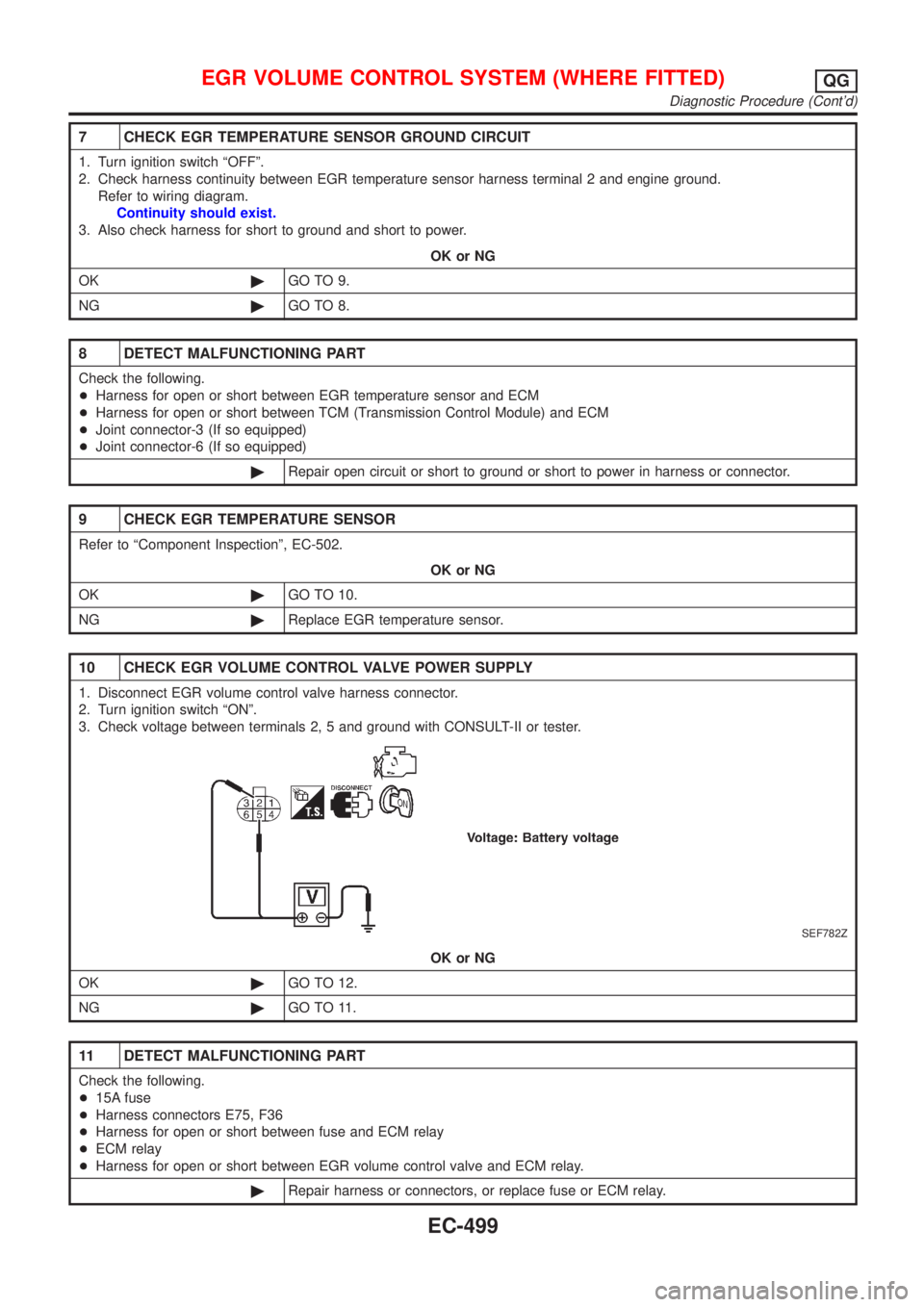
10 CHECK EGR VOLUME CONTROL VALVE POWER SUPPLY
1. Disconnect EGR volume control valve harness connector.
2. Turn ignition switch ªONº.
3. Check voltage between terminals 2, 5 and ground with CONSULT-II or tester.
SEF782Z
OK or NG
OK©GO TO 12.
NG©GO TO 11.
11 DETECT MALFUNCTIONING PART
Check the following.
+15A fuse
+Harness connectors E75, F36
+Harness for open or short between fuse and ECM relay
+ECM relay
+Harness for open or short between EGR volume control valve and ECM relay.
©Repair harness or connectors, or replace fuse or ECM relay.
EGR VOLUME CONTROL SYSTEM (WHERE FITTED)QG
Diagnostic Procedure (Cont'd)
EC-499
Page 1224 of 2898

12 CHECK OUTPUT SIGNAL CIRCUIT
1. Turn ignition switch ªOFFº.
2. Disconnect ECM harness connector.
3. Check harness continuity between
ECM terminal 8 and EGR volume control valve terminal 1,
ECM terminal 9 and EGR volume control valve terminal 4,
ECM terminal 17 and EGR volume control valve terminal 3,
ECM terminal 18 and EGR volume control valve terminal 6.
Refer to wiring diagram.
Continuity should exist.
4. Also check harness for short to ground and short to power.
OK or NG
OK©GO TO 13.
NG©Repair open circuit, short to ground or short to power in harness connectors.
13 CHECK EGR PASSAGE
Check EGR passage for clogging and cracks.
OK or NG
OK©GO TO 14.
NG©Repair or replace EGR passage.
14 CHECK EGR VOLUME CONTROL VALVE
Refer to ªCOMPONENT INSPECTIONº, EC-501.
OK or NG
OK©GO TO 15.
NG©Replace EGR volume control valve.
15 CHECK INTERMITTENT INCIDENT
Perform ªTROUBLE DIAGNOSIS FOR INTERMITTENT INCIDENTº, EC-177.
©INSPECTION END
EGR VOLUME CONTROL SYSTEM (WHERE FITTED)QG
Diagnostic Procedure (Cont'd)
EC-500