2001 NISSAN ALMERA ignition
[x] Cancel search: ignitionPage 1118 of 2898
SEF608Y
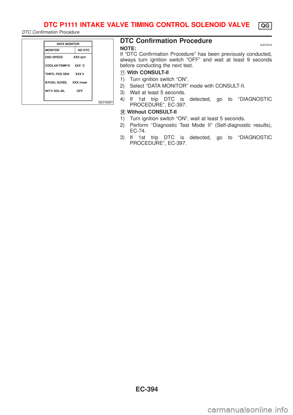
DTC Confirmation ProcedureNJEC0518NOTE:
If ªDTC Confirmation Procedureº has been previously conducted,
always turn ignition switch ªOFFº and wait at least 9 seconds
before conducting the next test.
With CONSULT-II
1) Turn ignition switch ªONº.
2) Select ªDATA MONITORº mode with CONSULT-II.
3) Wait at least 5 seconds.
4) If 1st trip DTC is detected, go to ªDIAGNOSTIC
PROCEDUREº, EC-397.
Without CONSULT-II
1) Turn ignition switch ªONº, wait at least 5 seconds.
2) Perform ªDiagnostic Test Mode IIº (Self-diagnostic results),
EC-74.
3) If 1st trip DTC is detected, go to ªDIAGNOSTIC
PROCEDUREº, EC-397.
D T C P 1111INTAKE VALVE TIMING CONTROL SOLENOID VALVEQG
DTC Confirmation Procedure
EC-394
Page 1121 of 2898
Diagnostic ProcedureNJEC0520
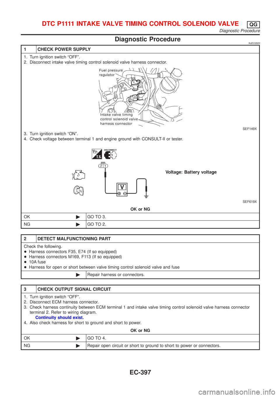
1 CHECK POWER SUPPLY
1. Turn ignition switch ªOFFº.
2. Disconnect intake valve timing control solenoid valve harness connector.
SEF149X
3. Turn ignition switch ªONº.
4. Check voltage between terminal 1 and engine ground with CONSULT-II or tester.
SEF619X
OK or NG
OK©GO TO 3.
NG©GO TO 2.
2 DETECT MALFUNCTIONING PART
Check the following.
+Harness connectors F35, E74 (If so equipped)
+Harness connectors M169, F113 (If so equipped)
+10A fuse
+Harness for open or short between valve timing control solenoid valve and fuse
©Repair harness or connectors.
3 CHECK OUTPUT SIGNAL CIRCUIT
1. Turn ignition switch ªOFFº.
2. Disconnect ECM harness connector.
3. Check harness continuity between ECM terminal 1 and intake valve timing control solenoid valve harness connector
terminal 2. Refer to wiring diagram.
Continuity should exist.
4. Also check harness for short to ground and short to power.
OK or NG
OK©GO TO 4.
NG©Repair open circuit or short to ground to short to power or connectors.
D T C P 1111INTAKE VALVE TIMING CONTROL SOLENOID VALVEQG
Diagnostic Procedure
EC-397
Page 1123 of 2898
DescriptionNJEC0522SYSTEM DESCRIPTIONNJEC0522S01
Sensor Input Signal to ECMECM func-
tionActuator
Throttle position sensor Throttle position
Swirl con-
trol valve
system
controlSwirl control valve control sole-
noid valve via swirl control
valve Ignition switch Start signal
Crankshaft position sensor (POS) Engine speed
Camshaft position sensor (PHASE) Engine speed and cylinder number
Mass air flow sensor Amount of intake air
Engine coolant temperature sensor Engine coolant temperature
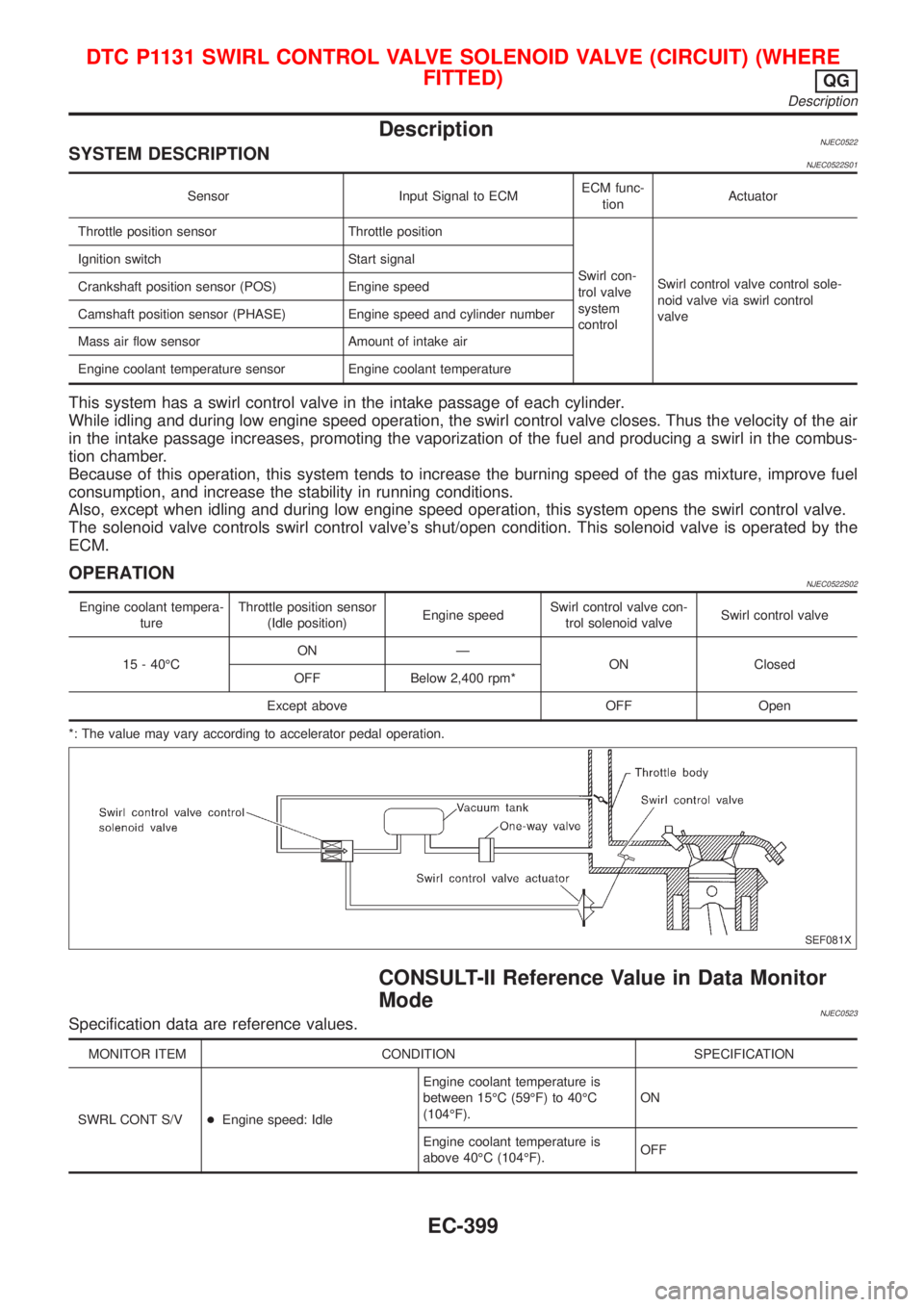
This system has a swirl control valve in the intake passage of each cylinder.
While idling and during low engine speed operation, the swirl control valve closes. Thus the velocity of the air
in the intake passage increases, promoting the vaporization of the fuel and producing a swirl in the combus-
tion chamber.
Because of this operation, this system tends to increase the burning speed of the gas mixture, improve fuel
consumption, and increase the stability in running conditions.
Also, except when idling and during low engine speed operation, this system opens the swirl control valve.
The solenoid valve controls swirl control valve's shut/open condition. This solenoid valve is operated by the
ECM.
OPERATIONNJEC0522S02
Engine coolant tempera-
tureThrottle position sensor
(Idle position)Engine speedSwirl control valve con-
trol solenoid valveSwirl control valve
15 - 40ÉCON Ð
ON Closed
OFF Below 2,400 rpm*
Except above OFF Open
*: The value may vary according to accelerator pedal operation.
SEF081X
CONSULT-II Reference Value in Data Monitor
Mode
NJEC0523Specification data are reference values.
MONITOR ITEM CONDITION SPECIFICATION
SWRL CONT S/V+Engine speed: IdleEngine coolant temperature is
between 15ÉC (59ÉF) to 40ÉC
(104ÉF).ON
Engine coolant temperature is
above 40ÉC (104ÉF).OFF
DTC P1131 SWIRL CONTROL VALVE SOLENOID VALVE (CIRCUIT) (WHERE
FITTED)
QG
Description
EC-399
Page 1124 of 2898
ECM Terminals and Reference Value=NJEC0524Specification data are reference values and are measured between each terminal and ground.
CAUTION:
Do not use ECM ground terminals when measuring input/output voltage. Doing so may result in dam-
age to the ECM's transistor. Use a ground other than ECM terminals, such as the ground.
TERMI-
NAL
NO.WIRE
COLORITEM CONDITION DATA (DC Voltage)
104 SBSwirl control valve control
solenoid valve[Engine is running]
+Engine coolant temperature is between 15ÉC
(59ÉF) to 40ÉC (104ÉF).
+Idle speed0-1V
[Engine is running]
+Engine coolant temperature is above 40ÉC
(104ÉF).
+Idle speedBATTERY VOLTAGE
(11 - 14V)
SEF098X
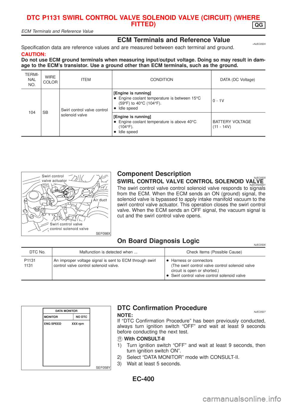
Component DescriptionNJEC0525SWIRL CONTROL VALVE CONTROL SOLENOID VALVENJEC0525S01The swirl control valve control solenoid valve responds to signals
from the ECM. When the ECM sends an ON (ground) signal, the
solenoid valve is bypassed to apply intake manifold vacuum to the
swirl control valve actuator. This operation closes the swirl control
valve. When the ECM sends an OFF signal, the vacuum signal is
cut and the swirl control valve opens.
On Board Diagnosis LogicNJEC0526
DTC No. Malfunction is detected when ... Check Items (Possible Cause)
P1131
1131An improper voltage signal is sent to ECM through swirl
control valve control solenoid valve.+Harness or connectors
(The swirl control valve control solenoid valve
circuit is open or shorted.)
+Swirl control valve control solenoid valve
SEF058Y
DTC Confirmation ProcedureNJEC0527NOTE:
If ªDTC Confirmation Procedureº has been previously conducted,
always turn ignition switch ªOFFº and wait at least 9 seconds
before conducting the next test.
With CONSULT-II
1) Turn ignition switch ªOFFº and wait at least 9 seconds, then
turn ignition switch ONº.
2) Select ªDATA MONITORº mode with CONSULT-II.
3) Wait at least 5 seconds.
DTC P1131 SWIRL CONTROL VALVE SOLENOID VALVE (CIRCUIT) (WHERE
FITTED)
QG
ECM Terminals and Reference Value
EC-400
Page 1127 of 2898
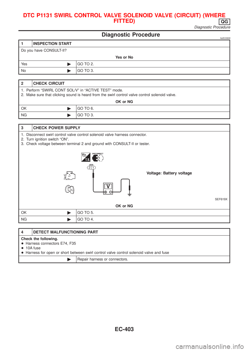
Diagnostic ProcedureNJEC0529
1 INSPECTION START
Do you have CONSULT-II?
YesorNo
Ye s©GO TO 2.
No©GO TO 3.
2 CHECK CIRCUIT
1. Perform ªSWIRL CONT SOL/Vº in ªACTIVE TESTº mode.
2. Make sure that clicking sound is heard from the swirl control valve control solenoid valve.
OK or NG
OK©GO TO 6.
NG©GO TO 3.
3 CHECK POWER SUPPLY
1. Disconnect swirl control valve control solenoid valve harness connector.
2. Turn ignition switch ªONº.
3. Check voltage between terminal 2 and ground with CONSULT-II or tester.
SEF619X
OK or NG
OK©GO TO 5.
NG©GO TO 4.
4 DETECT MALFUNCTIONING PART
Check the following.
+Harness connectors E74, F35
+10A fuse
+Harness for open or short between swirl control valve control solenoid valve and fuse
©Repair harness or connectors.
DTC P1131 SWIRL CONTROL VALVE SOLENOID VALVE (CIRCUIT) (WHERE
FITTED)
QG
Diagnostic Procedure
EC-403
Page 1128 of 2898
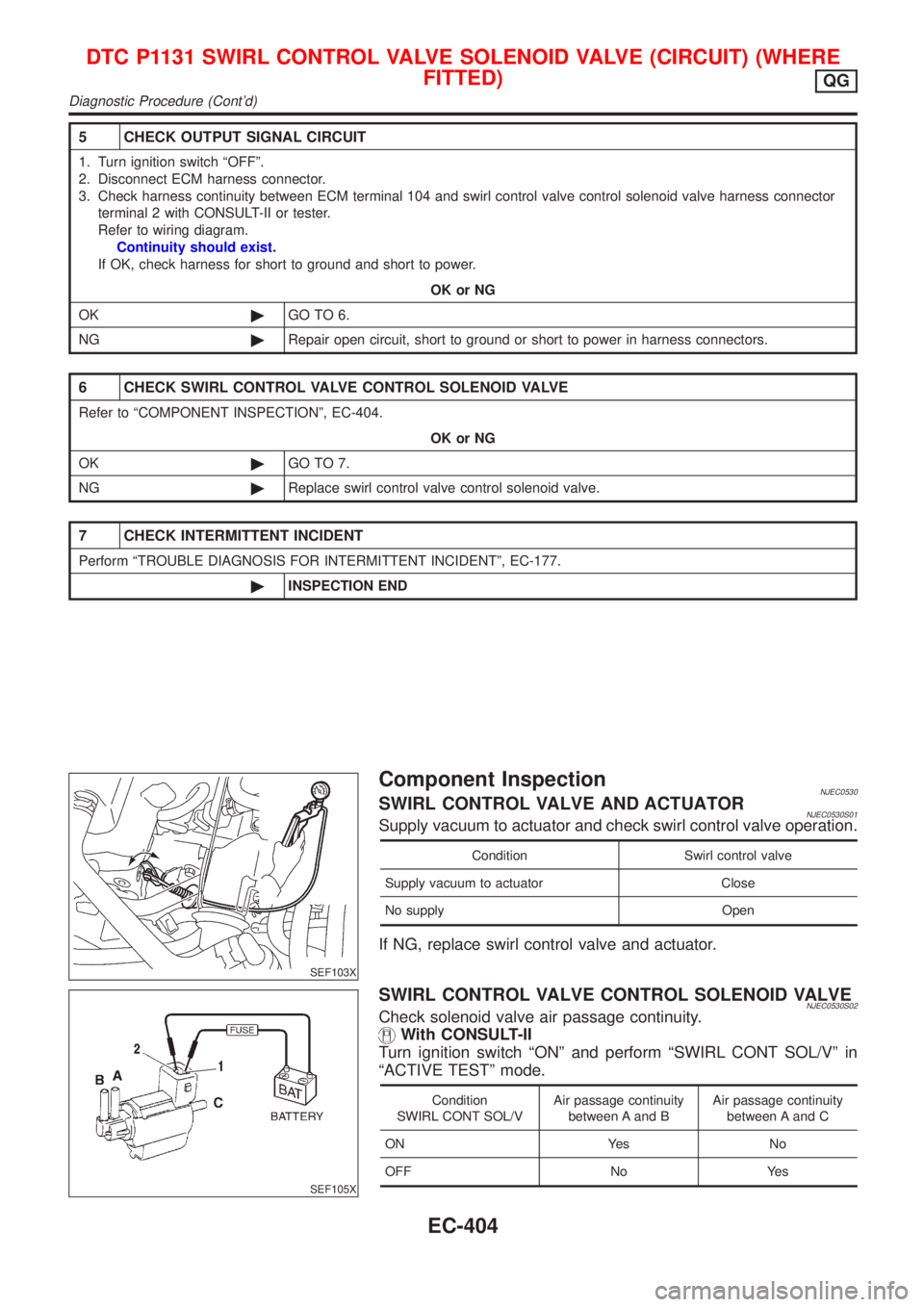
5 CHECK OUTPUT SIGNAL CIRCUIT
1. Turn ignition switch ªOFFº.
2. Disconnect ECM harness connector.
3. Check harness continuity between ECM terminal 104 and swirl control valve control solenoid valve harness connector
terminal 2 with CONSULT-II or tester.
Refer to wiring diagram.
Continuity should exist.
If OK, check harness for short to ground and short to power.
OK or NG
OK©GO TO 6.
NG©Repair open circuit, short to ground or short to power in harness connectors.
6 CHECK SWIRL CONTROL VALVE CONTROL SOLENOID VALVE
Refer to ªCOMPONENT INSPECTIONº, EC-404.
OK or NG
OK©GO TO 7.
NG©Replace swirl control valve control solenoid valve.
7 CHECK INTERMITTENT INCIDENT
Perform ªTROUBLE DIAGNOSIS FOR INTERMITTENT INCIDENTº, EC-177.
©INSPECTION END
SEF103X
Component InspectionNJEC0530SWIRL CONTROL VALVE AND ACTUATORNJEC0530S01Supply vacuum to actuator and check swirl control valve operation.
Condition Swirl control valve
Supply vacuum to actuator Close
No supply Open
If NG, replace swirl control valve and actuator.
SEF105X
SWIRL CONTROL VALVE CONTROL SOLENOID VALVENJEC0530S02Check solenoid valve air passage continuity.
With CONSULT-II
Turn ignition switch ªONº and perform ªSWIRL CONT SOL/Vº in
ªACTIVE TESTº mode.
Condition
SWIRL CONT SOL/VAir passage continuity
between A and BAir passage continuity
between A and C
ON Yes No
OFF No Yes
DTC P1131 SWIRL CONTROL VALVE SOLENOID VALVE (CIRCUIT) (WHERE
FITTED)
QG
Diagnostic Procedure (Cont'd)
EC-404
Page 1130 of 2898
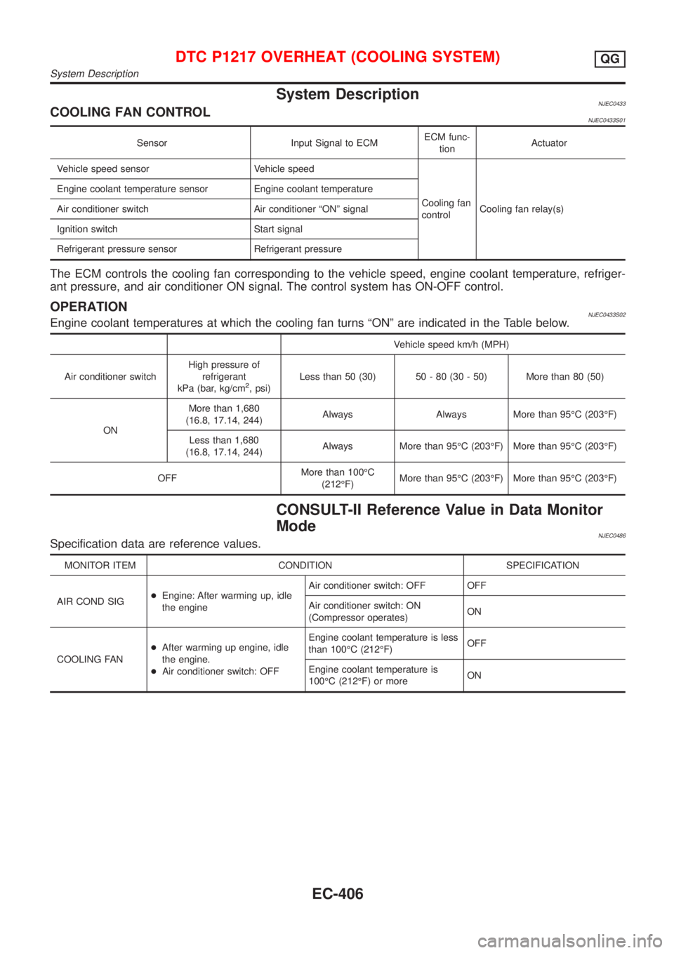
System DescriptionNJEC0433COOLING FAN CONTROLNJEC0433S01
Sensor Input Signal to ECMECM func-
tionActuator
Vehicle speed sensor Vehicle speed
Cooling fan
controlCooling fan relay(s) Engine coolant temperature sensor Engine coolant temperature
Air conditioner switch Air conditioner ªONº signal
Ignition switch Start signal
Refrigerant pressure sensor Refrigerant pressure
The ECM controls the cooling fan corresponding to the vehicle speed, engine coolant temperature, refriger-
ant pressure, and air conditioner ON signal. The control system has ON-OFF control.
OPERATIONNJEC0433S02Engine coolant temperatures at which the cooling fan turns ªONº are indicated in the Table below.
Vehicle speed km/h (MPH)
Air conditioner switchHigh pressure of
refrigerant
kPa (bar, kg/cm
2, psi)Less than 50 (30) 50 - 80 (30 - 50) More than 80 (50)
ONMore than 1,680
(16.8, 17.14, 244)Always Always More than 95ÉC (203ÉF)
Less than 1,680
(16.8, 17.14, 244)Always More than 95ÉC (203ÉF) More than 95ÉC (203ÉF)
OFFMore than 100ÉC
(212ÉF)More than 95ÉC (203ÉF) More than 95ÉC (203ÉF)
CONSULT-II Reference Value in Data Monitor
Mode
NJEC0486Specification data are reference values.
MONITOR ITEM CONDITION SPECIFICATION
AIR COND SIG+Engine: After warming up, idle
the engineAir conditioner switch: OFF OFF
Air conditioner switch: ON
(Compressor operates)ON
COOLING FAN+After warming up engine, idle
the engine.
+Air conditioner switch: OFFEngine coolant temperature is less
than 100ÉC (212ÉF)OFF
Engine coolant temperature is
100ÉC (212ÉF) or moreON
DTC P1217 OVERHEAT (COOLING SYSTEM)QG
System Description
EC-406
Page 1131 of 2898
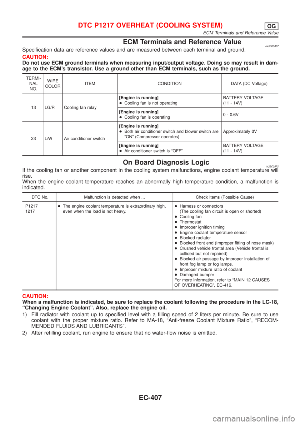
ECM Terminals and Reference Value=NJEC0487Specification data are reference values and are measured between each terminal and ground.
CAUTION:
Do not use ECM ground terminals when measuring input/output voltage. Doing so may result in dam-
age to the ECM's transistor. Use a ground other than ECM terminals, such as the ground.
TERMI-
NAL
NO.WIRE
COLORITEM CONDITION DATA (DC Voltage)
13 LG/R Cooling fan relay[Engine is running]
+Cooling fan is not operatingBATTERY VOLTAGE
(11 - 14V)
[Engine is running]
+Cooling fan is operating0 - 0.6V
23 L/W Air conditioner switch[Engine is running]
+Both air conditioner switch and blower switch are
ªONº (Compressor operates)Approximately 0V
[Engine is running]
+Air conditioner switch is ªOFFºBATTERY VOLTAGE
(11 - 14V)
On Board Diagnosis LogicNJEC0572If the cooling fan or another component in the cooling system malfunctions, engine coolant temperature will
rise.
When the engine coolant temperature reaches an abnormally high temperature condition, a malfunction is
indicated.
DTC No. Malfunction is detected when ... Check Items (Possible Cause)
P1217
1217+The engine coolant temperature is extraordinary high,
even when the load is not heavy.+Harness or connectors
(The cooling fan circuit is open or shorted)
+Cooling fan
+Thermostat
+Improper ignition timing
+Engine coolant temperature sensor
+Blocked radiator
+Blocked front end (Improper fitting of nose mask)
+Crushed vehicle frontal area (Vehicle frontal is
collided but not repaired)
+Blocked air passage by improper installation of
front fog lamp or fog lamps.
+Improper mixture ratio of coolant
+Damaged bumper
For more information, refer to ªMAIN 12 CAUSES
OF OVERHEATINGº, EC-416.
CAUTION:
When a malfunction is indicated, be sure to replace the coolant following the procedure in the LC-18,
ªChanging Engine Coolantº. Also, replace the engine oil.
1) Fill radiator with coolant up to specified level with a filling speed of 2 liters per minute. Be sure to use
coolant with the proper mixture ratio. Refer to MA-18, ªAnti-freeze Coolant Mixture Ratioº, ªRECOM-
MENDED FLUIDS AND LUBRICANTSº.
2) After refilling coolant, run engine to ensure that no water-flow noise is emitted.
DTC P1217 OVERHEAT (COOLING SYSTEM)QG
ECM Terminals and Reference Value
EC-407