Page 1468 of 2898
3 CHECK COOLING FAN GROUND CIRCUIT FOR OPEN AND SHORT
1. Turn ignition switch ªOFFº.
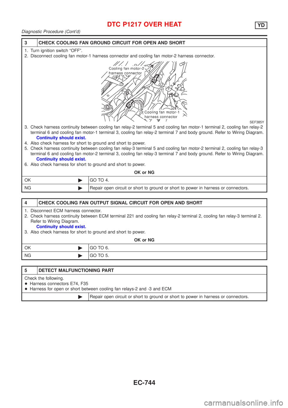
2. Disconnect cooling fan motor-1 harness connector and cooling fan motor-2 harness connector.
SEF385Y
3. Check harness continuity between cooling fan relay-2 terminal 5 and cooling fan motor-1 terminal 2, cooling fan relay-2
terminal 6 and cooling fan motor-1 terminal 3, cooling fan relay-2 terminal 7 and body ground. Refer to Wiring Diagram.
Continuity should exist.
4. Also check harness for short to ground and short to power.
5. Check harness continuity between cooling fan relay-3 terminal 5 and cooling fan motor-2 terminal 2, cooling fan relay-3
terminal 6 and cooling fan motor-2 terminal 3, cooling fan relay-3 terminal 7 and body ground. Refer to Wiring Diagram.
Continuity should exist.
6. Also check harness for short to ground and short to power.
OK or NG
OK©GO TO 4.
NG©Repair open circuit or short to ground or short to power in harness or connectors.
4 CHECK COOLING FAN OUTPUT SIGNAL CIRCUIT FOR OPEN AND SHORT
1. Disconnect ECM harness connector.
2. Check harness continuity between ECM terminal 221 and cooling fan relay-2 terminal 2, cooling fan relay-3 terminal 2.
Refer to Wiring Diagram.
Continuity should exist.
3. Also check harness for short to ground and short to power.
OK or NG
OK©GO TO 6.
NG©GO TO 5.
5 DETECT MALFUNCTIONING PART
Check the following.
+Harness connectors E74, F35
+Harness for open or short between cooling fan relays-2 and -3 and ECM
©Repair open circuit or short to ground or short to power in harness or connectors.
DTC P1217 OVER HEATYD
Diagnostic Procedure (Cont'd)
EC-744
Page 1475 of 2898
2 DETECT MALFUNCTIONING PART
Check the following.
+Fuse block (J/B) connector E104
+10A fuse
+40A fusible link
+Harness for open or short between cooling fan relay-1 and fuse
+Harness for open or short between cooling fan relay-1 and battery
©Repair open circuit or short to ground or short to power in harness or connectors.
3 CHECK COOLING FAN GROUND CIRCUIT FOR OPEN AND SHORT-I
1. Turn ignition switch ªOFFº.
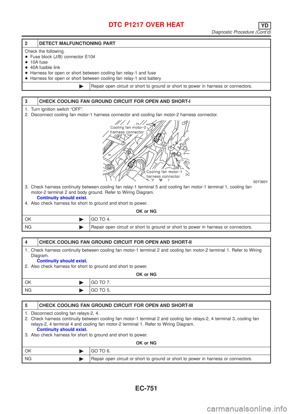
2. Disconnect cooling fan motor-1 harness connector and cooling fan motor-2 harness connector.
SEF385Y
3. Check harness continuity between cooling fan relay-1 terminal 5 and cooling fan motor-1 terminal 1, cooling fan
motor-2 terminal 2 and body ground. Refer to Wiring Diagram.
Continuity should exist.
4. Also check harness for short to ground and short to power.
OK or NG
OK©GO TO 4.
NG©Repair open circuit or short to ground or short to power in harness or connectors.
4 CHECK COOLING FAN GROUND CIRCUIT FOR OPEN AND SHORT-II
1. Check harness continuity between cooling fan motor-1 terminal 2 and cooling fan motor-2 terminal 1. Refer to Wiring
Diagram.
Continuity should exist.
2. Also check harness for short to ground and short to power.
OK or NG
OK©GO TO 7.
NG©GO TO 5.
5 CHECK COOLING FAN GROUND CIRCUIT FOR OPEN AND SHORT-III
1. Disconnect cooling fan relays-2, 4.
2. Check harness continuity between cooling fan motor-1 terminal 2 and cooling fan relays-2, 4 terminal 3, cooling fan
relays-2, 4 terminal 4 and cooling fan motor-2 terminal 1. Refer to Wiring Diagram.
Continuity should exist.
3. Also check harness for short to ground and short to power.
OK or NG
OK©GO TO 6.
NG©Repair open circuit or short to ground or short to power in harness or connectors.
DTC P1217 OVER HEATYD
Diagnostic Procedure (Cont'd)
EC-751
Page 1476 of 2898
6 CHECK COOLING FAN RELAY-2, 4
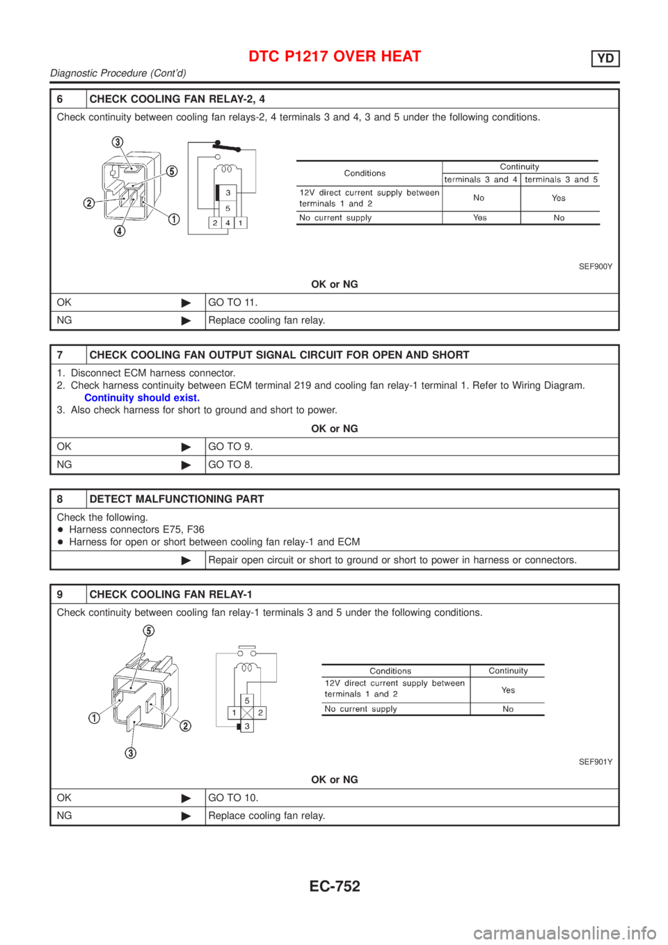
Check continuity between cooling fan relays-2, 4 terminals 3 and 4, 3 and 5 under the following conditions.
SEF900Y
OK or NG
OK©GO TO 11.
NG©Replace cooling fan relay.
7 CHECK COOLING FAN OUTPUT SIGNAL CIRCUIT FOR OPEN AND SHORT
1. Disconnect ECM harness connector.
2. Check harness continuity between ECM terminal 219 and cooling fan relay-1 terminal 1. Refer to Wiring Diagram.
Continuity should exist.
3. Also check harness for short to ground and short to power.
OK or NG
OK©GO TO 9.
NG©GO TO 8.
8 DETECT MALFUNCTIONING PART
Check the following.
+Harness connectors E75, F36
+Harness for open or short between cooling fan relay-1 and ECM
©Repair open circuit or short to ground or short to power in harness or connectors.
9 CHECK COOLING FAN RELAY-1
Check continuity between cooling fan relay-1 terminals 3 and 5 under the following conditions.
SEF901Y
OK or NG
OK©GO TO 10.
NG©Replace cooling fan relay.
DTC P1217 OVER HEATYD
Diagnostic Procedure (Cont'd)
EC-752
Page 1478 of 2898
2 DETECT MALFUNCTIONING PART
Check the following.
+40A fusible link
+Harness for open or short between cooling fan relays-2, 3, 4 and fuse
+Harness for open or short between cooling fan relay-3 and fusible link
©Repair harness or connectors.
3 CHECK COOLING FAN GROUND CIRCUIT FOR OPEN AND SHORT
1. Turn ignition switch ªOFFº.
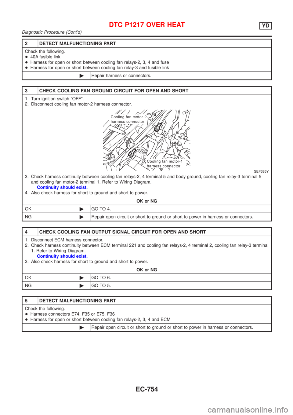
2. Disconnect cooling fan motor-2 harness connector.
SEF385Y
3. Check harness continuity between cooling fan relays-2, 4 terminal 5 and body ground, cooling fan relay-3 terminal 5
and cooling fan motor-2 terminal 1. Refer to Wiring Diagram.
Continuity should exist.
4. Also check harness for short to ground and short to power.
OK or NG
OK©GO TO 4.
NG©Repair open circuit or short to ground or short to power in harness or connectors.
4 CHECK COOLING FAN OUTPUT SIGNAL CIRCUIT FOR OPEN AND SHORT
1. Disconnect ECM harness connector.
2. Check harness continuity between ECM terminal 221 and cooling fan relays-2, 4 terminal 2, cooling fan relay-3 terminal
1. Refer to Wiring Diagram.
Continuity should exist.
3. Also check harness for short to ground and short to power.
OK or NG
OK©GO TO 6.
NG©GO TO 5.
5 DETECT MALFUNCTIONING PART
Check the following.
+Harness connectors E74, F35 or E75, F36
+Harness for open or short between cooling fan relays-2, 3, 4 and ECM
©Repair open circuit or short to ground or short to power in harness or connectors.
DTC P1217 OVER HEATYD
Diagnostic Procedure (Cont'd)
EC-754
Page 1484 of 2898
Wiring DiagramNJEC0732SEDAN MODELS AND HATCHBACK MODELS WITH ECM IN ENGINE COMPARTMENTNJEC0732S01
HEC825
DTC P1241 P7´F/INJ TIMG FBYD
Wiring Diagram
EC-760
Page 1485 of 2898
HATCHBACK MODELS WITH ECM IN CABINNJEC0732S02
HEC993
DTC P1241 P7´F/INJ TIMG FBYD
Wiring Diagram (Cont'd)
EC-761
Page 1487 of 2898
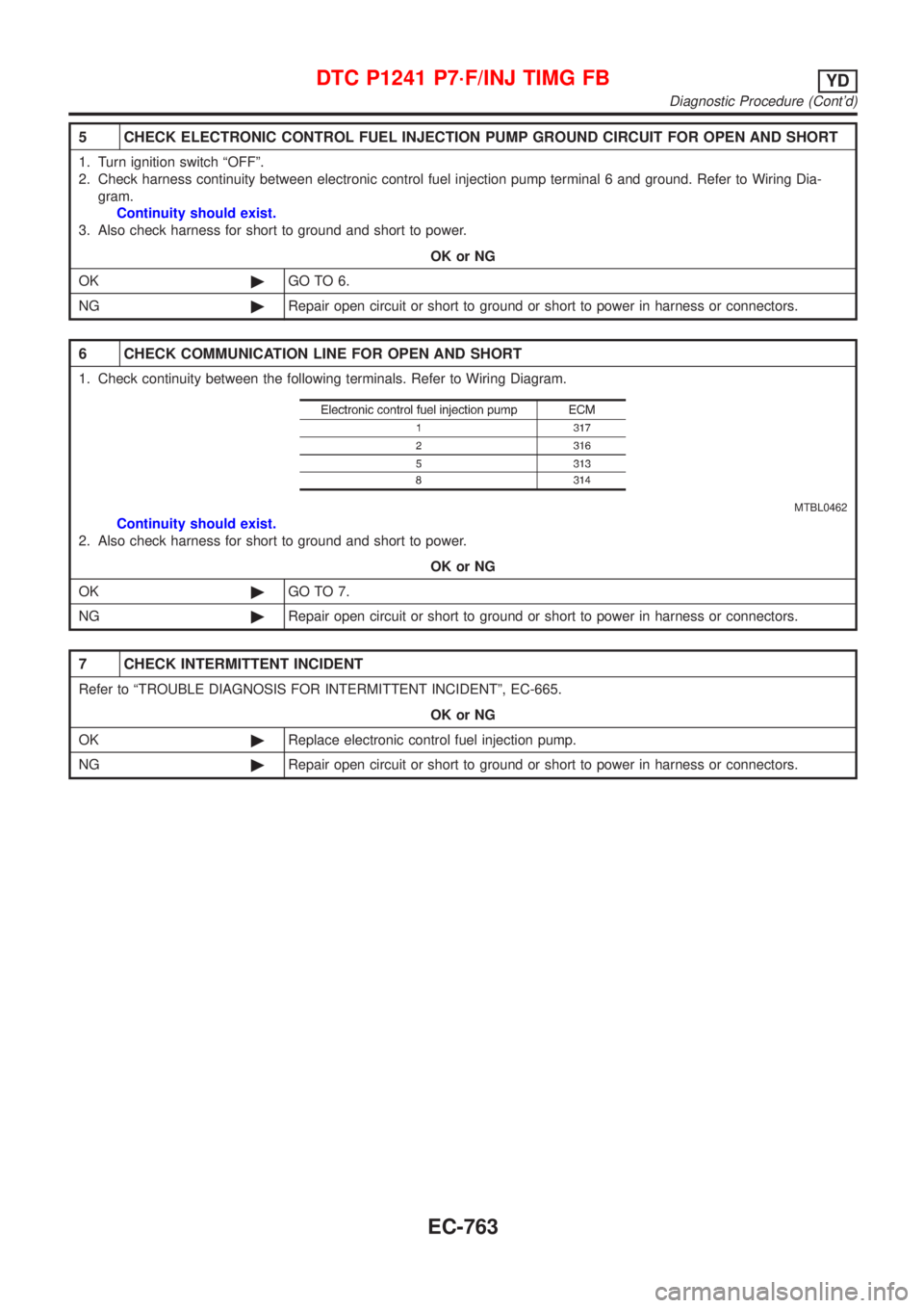
5 CHECK ELECTRONIC CONTROL FUEL INJECTION PUMP GROUND CIRCUIT FOR OPEN AND SHORT
1. Turn ignition switch ªOFFº.
2. Check harness continuity between electronic control fuel injection pump terminal 6 and ground. Refer to Wiring Dia-
gram.
Continuity should exist.
3. Also check harness for short to ground and short to power.
OK or NG
OK©GO TO 6.
NG©Repair open circuit or short to ground or short to power in harness or connectors.
6 CHECK COMMUNICATION LINE FOR OPEN AND SHORT
1. Check continuity between the following terminals. Refer to Wiring Diagram.
MTBL0462
Continuity should exist.
2. Also check harness for short to ground and short to power.
OK or NG
OK©GO TO 7.
NG©Repair open circuit or short to ground or short to power in harness or connectors.
7 CHECK INTERMITTENT INCIDENT
Refer to ªTROUBLE DIAGNOSIS FOR INTERMITTENT INCIDENTº, EC-665.
OK or NG
OK©Replace electronic control fuel injection pump.
NG©Repair open circuit or short to ground or short to power in harness or connectors.
DTC P1241 P7´F/INJ TIMG FBYD
Diagnostic Procedure (Cont'd)
EC-763
Page 1491 of 2898
Wiring DiagramNJEC0719SEDAN MODELS AND HATCHBACK MODELS WITH ECM IN ENGINE COMPARTMENTNJEC0719S01
HEC825
DTC P1251 P4´SPILL/V CIRCYD
Wiring Diagram
EC-767