Page 1535 of 2898

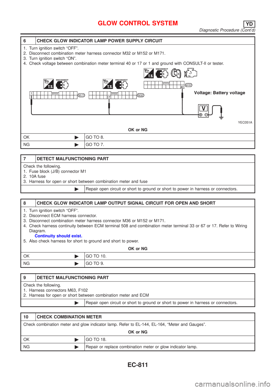
6 CHECK GLOW INDICATOR LAMP POWER SUPPLY CIRCUIT
1. Turn ignition switch ªOFFº.
2. Disconnect combination meter harness connector M32 or M152 or M171.
3. Turn ignition switch ªONº.
4. Check voltage between combination meter terminal 40 or 17 or 1 and ground with CONSULT-II or tester.
YEC051A
OK or NG
OK©GO TO 8.
NG©GO TO 7.
7 DETECT MALFUNCTIONING PART
Check the following.
1. Fuse block (J/B) connector M1
2. 10A fuse
3. Harness for open or short between combination meter and fuse
©Repair open circuit or short to ground or short to power in harness or connectors.
8 CHECK GLOW INDICATOR LAMP OUTPUT SIGNAL CIRCUIT FOR OPEN AND SHORT
1. Turn ignition switch ªOFFº.
2. Disconnect ECM harness connector.
3. Disconnect combination meter harness connector M36 or M152 or M171.
4. Check harness continuity between ECM terminal 508 and combination meter terminal 33 or 67 or 17. Refer to Wiring
Diagram.
Continuity should exist.
5. Also check harness for short to ground and short to power.
OK or NG
OK©GO TO 10.
NG©GO TO 9.
9 DETECT MALFUNCTIONING PART
Check the following.
1. Harness connectors M63, F102
2. Harness for open or short between combination meter and ECM
©Repair open circuit or short to ground or short to power in harness or connectors.
10 CHECK COMBINATION METER
Check combination meter and glow indicator lamp. Refer to EL-144, EL-164, ªMeter and Gaugesº.
OK or NG
OK©GO TO 18.
NG©Repair or replace combination meter or glow indicator lamp.
GLOW CONTROL SYSTEMYD
Diagnostic Procedure (Cont'd)
EC-811
Page 1536 of 2898

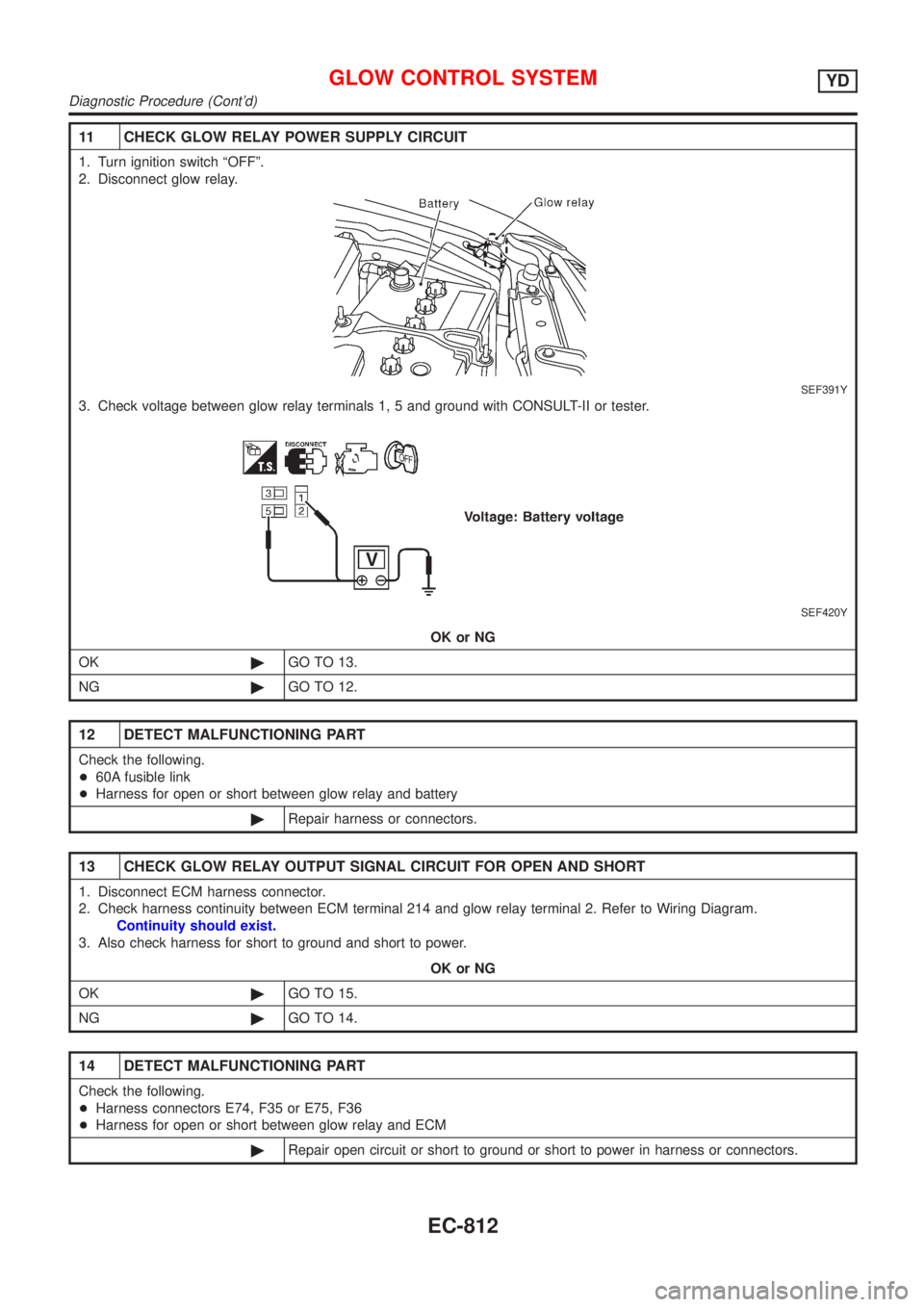
11 CHECK GLOW RELAY POWER SUPPLY CIRCUIT
1. Turn ignition switch ªOFFº.
2. Disconnect glow relay.
SEF391Y
3. Check voltage between glow relay terminals 1, 5 and ground with CONSULT-II or tester.
SEF420Y
OK or NG
OK©GO TO 13.
NG©GO TO 12.
12 DETECT MALFUNCTIONING PART
Check the following.
+60A fusible link
+Harness for open or short between glow relay and battery
©Repair harness or connectors.
13 CHECK GLOW RELAY OUTPUT SIGNAL CIRCUIT FOR OPEN AND SHORT
1. Disconnect ECM harness connector.
2. Check harness continuity between ECM terminal 214 and glow relay terminal 2. Refer to Wiring Diagram.
Continuity should exist.
3. Also check harness for short to ground and short to power.
OK or NG
OK©GO TO 15.
NG©GO TO 14.
14 DETECT MALFUNCTIONING PART
Check the following.
+Harness connectors E74, F35 or E75, F36
+Harness for open or short between glow relay and ECM
©Repair open circuit or short to ground or short to power in harness or connectors.
GLOW CONTROL SYSTEMYD
Diagnostic Procedure (Cont'd)
EC-812
Page 1537 of 2898

15 CHECK HARNESS CONTINUITY BETWEEN GLOW RELAY AND GLOW PLUG FOR OPEN AND SHORT
1. Disconnect glow plug harness connector.
2. Check harness continuity between glow relay terminal 3 and glow plug harness connector. Refer to Wiring Diagram.
Continuity should exist.
3. Also check harness for short to ground and short to power.
OK or NG
OK©GO TO 16.
NG©Repair open circuit or short to ground or short to power in harness or connectors.
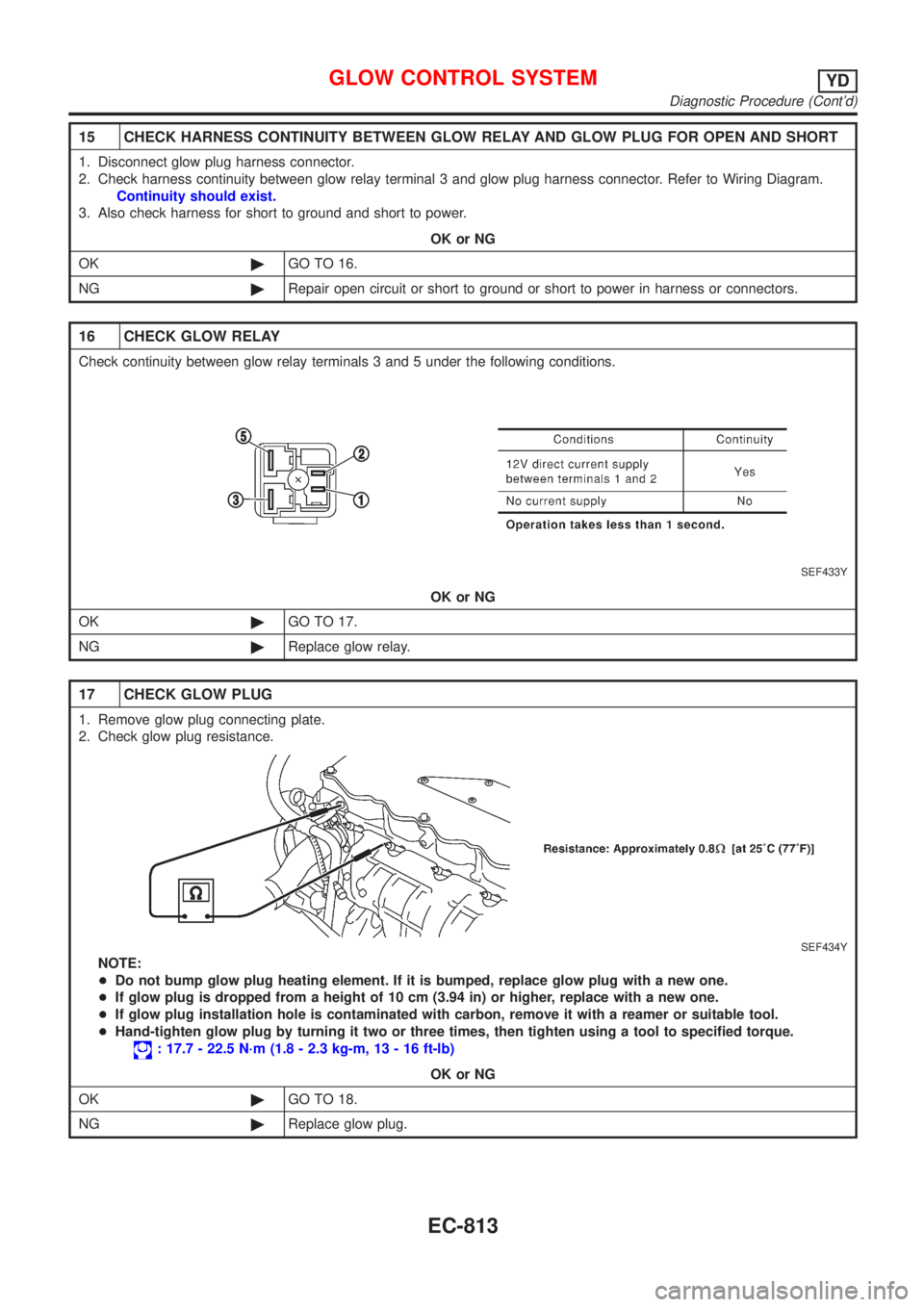
16 CHECK GLOW RELAY
Check continuity between glow relay terminals 3 and 5 under the following conditions.
SEF433Y
OK or NG
OK©GO TO 17.
NG©Replace glow relay.
17 CHECK GLOW PLUG
1. Remove glow plug connecting plate.
2. Check glow plug resistance.
SEF434Y
NOTE:
+Do not bump glow plug heating element. If it is bumped, replace glow plug with a new one.
+If glow plug is dropped from a height of 10 cm (3.94 in) or higher, replace with a new one.
+If glow plug installation hole is contaminated with carbon, remove it with a reamer or suitable tool.
+Hand-tighten glow plug by turning it two or three times, then tighten using a tool to specified torque.
: 17.7 - 22.5 N´m (1.8 - 2.3 kg-m, 13 - 16 ft-lb)
OK or NG
OK©GO TO 18.
NG©Replace glow plug.
GLOW CONTROL SYSTEMYD
Diagnostic Procedure (Cont'd)
EC-813
Page 1541 of 2898
Wiring Diagram=NJEC0767SEDAN MODELS AND HATCHBACK MODELS WITH ECM IN ENGINE COMPARTMENTNJEC0767S01
HEC831
EGR VOLUME CONTROL SYSTEMYD
Wiring Diagram
EC-817
Page 1542 of 2898
HATCHBACK MODELS WITH ECM IN CABINNJEC0767S02
HEC996
EGR VOLUME CONTROL SYSTEMYD
Wiring Diagram (Cont'd)
EC-818
Page 1544 of 2898

3 CHECK EGR VOLUME CONTROL VALVE POWER SUPPLY CIRCUIT-II
1. Turn ignition switch ªOFFº.
2. Disconnect ECM relay. (For ECM relay location, refer to ªEngine Control Component Parts Locationº.)
3. Check harness continuity between ECM relay terminal 5 and EGR volume control valve terminals 2 and 5. Refer to
Wiring Diagram.
Continuity should exist.
OK or NG
OK©GO TO 4.
NG©Repair open circuit or short to ground or short to power in harness or connectors.
4 CHECK EGR VOLUME CONTROL VALVE POWER SUPPLY CIRCUIT-III
Check voltage between ECM relay terminal 3 and ground with CONSULT-II or tester.
SEF413Y
OK or NG
OK©GO TO 6.
NG©GO TO 5.
5 DETECT MALFUNCTIONING PART
Check the following.
+Harness connectors E75, F36 (Sedan models and hatchback models with ECM in engine compartment)
+10A fuse
+Harness for open or short between ECM relay and battery
©Repair open circuit or short to ground or short to power in harness or connectors.
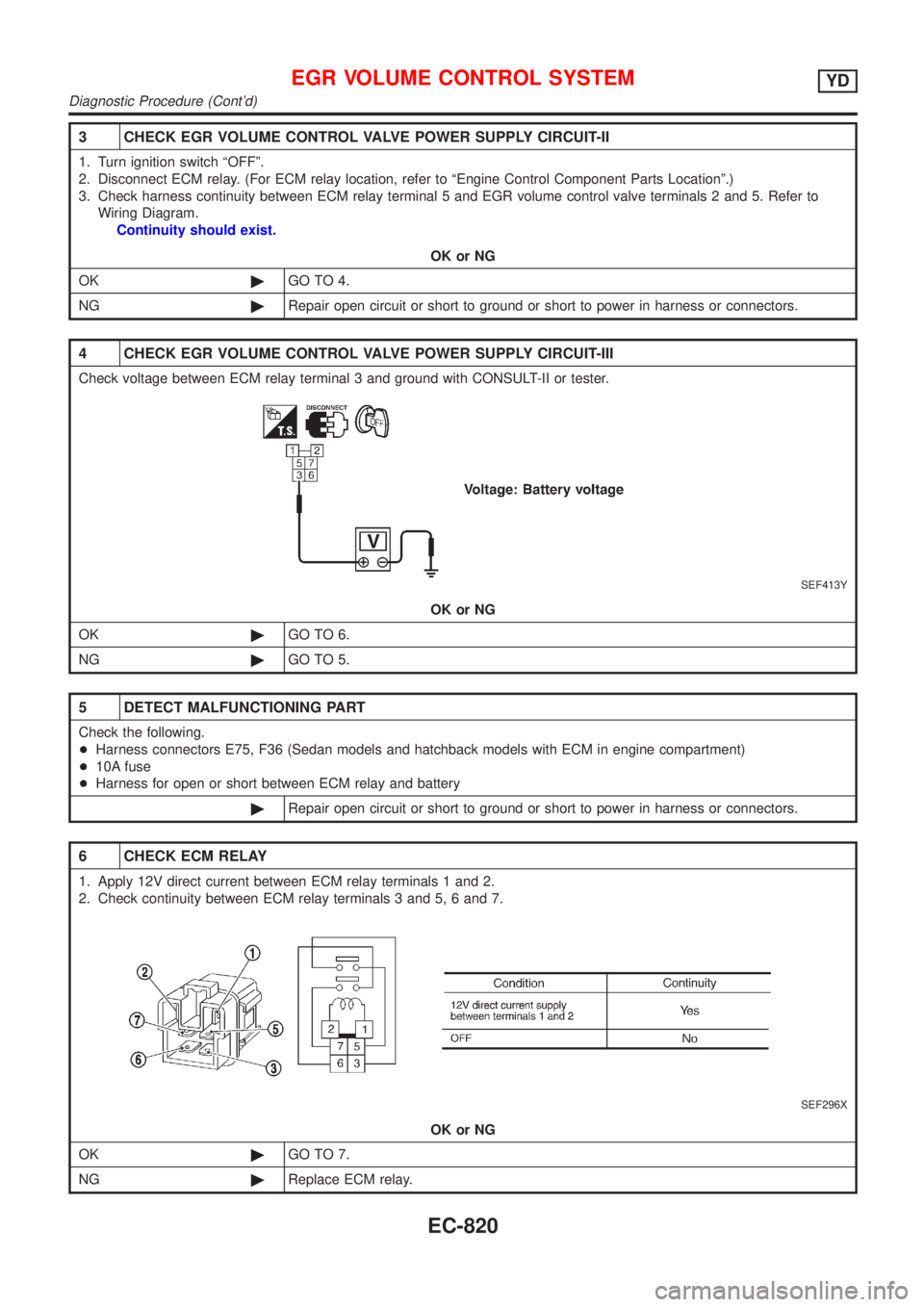
6 CHECK ECM RELAY
1. Apply 12V direct current between ECM relay terminals 1 and 2.
2. Check continuity between ECM relay terminals 3 and 5, 6 and 7.
SEF296X
OK or NG
OK©GO TO 7.
NG©Replace ECM relay.
EGR VOLUME CONTROL SYSTEMYD
Diagnostic Procedure (Cont'd)
EC-820
Page 1545 of 2898
7 CHECK EGR VOLUME CONTROL VALVE OUTPUT SIGNAL CIRCUIT FOR OPEN AND SHORT
1. Turn ignition switch ªOFFº.
2. Disconnect ECM harness connector.
3. Check harness continuity between ECM terminals and EGR volume control valve terminals as follows.
Refer to Wiring Diagram.
MTBL0463
Continuity should exist.
4. Also check harness for short to ground and short to power.
OK or NG
OK©GO TO 8.
NG©Repair open circuit or short to ground or short to power in harness or connectors.
8 CHECK EGR VOLUME CONTROL VALVE-I
Check resistance between EGR volume control valve terminal 2 and terminals 1, 3, terminal 5 and terminals 4, 6.
SEF414Y
OK or NG
OK (With CONSULT-II)©GO TO 9.
OK (Without CONSULT-
II)©GO TO 10.
NG©Replace EGR volume control valve.
EGR VOLUME CONTROL SYSTEMYD
Diagnostic Procedure (Cont'd)
EC-821
Page 1547 of 2898
Wiring DiagramNJEC0769
HEC834
START SIGNALYD
Wiring Diagram
EC-823