Page 1422 of 2898

Diagnostic ProcedureNJEC0692
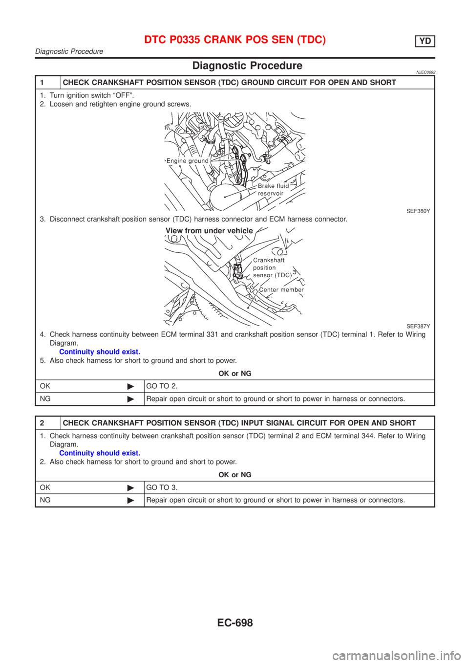
1 CHECK CRANKSHAFT POSITION SENSOR (TDC) GROUND CIRCUIT FOR OPEN AND SHORT
1. Turn ignition switch ªOFFº.
2. Loosen and retighten engine ground screws.
SEF380Y
3. Disconnect crankshaft position sensor (TDC) harness connector and ECM harness connector.
SEF387Y
4. Check harness continuity between ECM terminal 331 and crankshaft position sensor (TDC) terminal 1. Refer to Wiring
Diagram.
Continuity should exist.
5. Also check harness for short to ground and short to power.
OK or NG
OK©GO TO 2.
NG©Repair open circuit or short to ground or short to power in harness or connectors.
2 CHECK CRANKSHAFT POSITION SENSOR (TDC) INPUT SIGNAL CIRCUIT FOR OPEN AND SHORT
1. Check harness continuity between crankshaft position sensor (TDC) terminal 2 and ECM terminal 344. Refer to Wiring
Diagram.
Continuity should exist.
2. Also check harness for short to ground and short to power.
OK or NG
OK©GO TO 3.
NG©Repair open circuit or short to ground or short to power in harness or connectors.
DTC P0335 CRANK POS SEN (TDC)YD
Diagnostic Procedure
EC-698
Page 1427 of 2898
Wiring DiagramNJEC0658SEDANNJEC0658S01
HEC882
DTC P0500 VEHICLE SPEED SENYD
Wiring Diagram
EC-703
Page 1428 of 2898
HATCHBACKNJEC0658S02
NEF335A
DTC P0500 VEHICLE SPEED SENYD
Wiring Diagram (Cont'd)
EC-704
Page 1429 of 2898

Diagnostic ProcedureNJEC0659
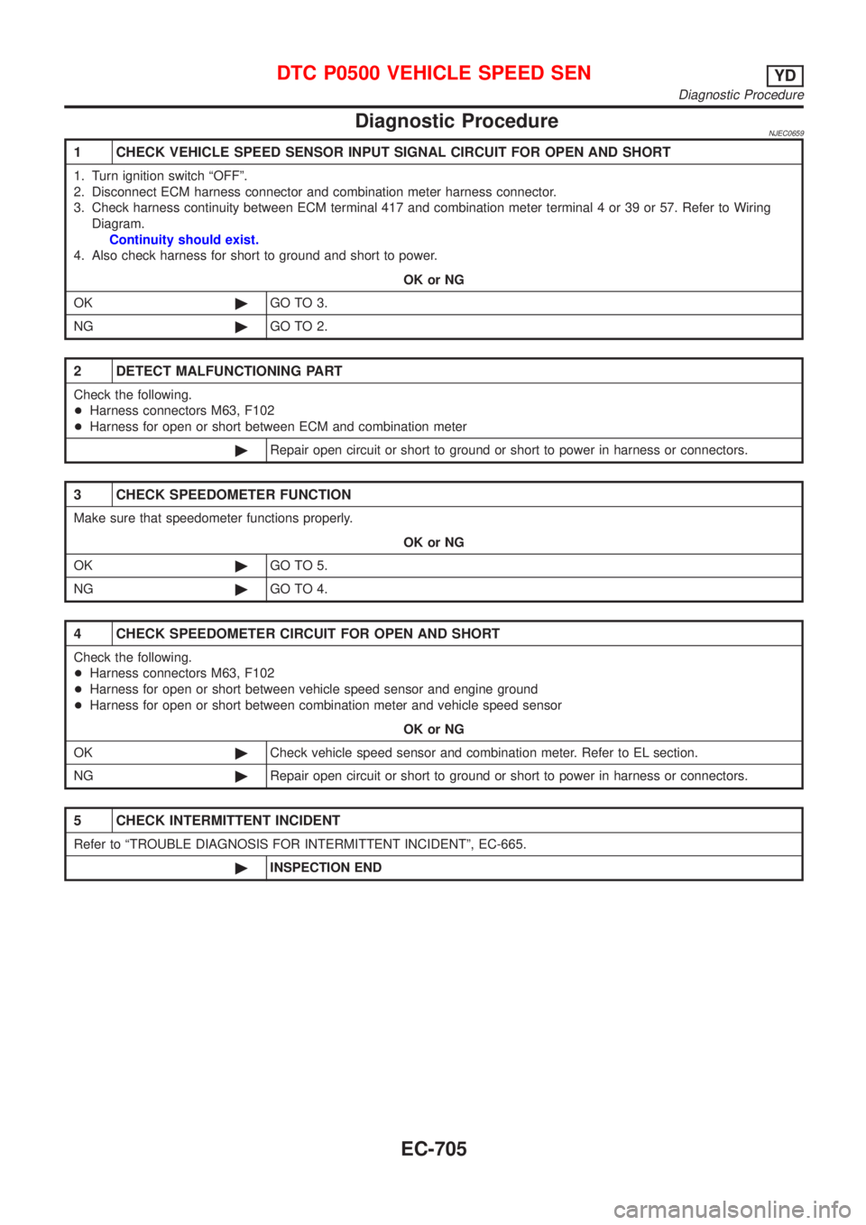
1 CHECK VEHICLE SPEED SENSOR INPUT SIGNAL CIRCUIT FOR OPEN AND SHORT
1. Turn ignition switch ªOFFº.
2. Disconnect ECM harness connector and combination meter harness connector.
3. Check harness continuity between ECM terminal 417 and combination meter terminal 4 or 39 or 57. Refer to Wiring
Diagram.
Continuity should exist.
4. Also check harness for short to ground and short to power.
OK or NG
OK©GO TO 3.
NG©GO TO 2.
2 DETECT MALFUNCTIONING PART
Check the following.
+Harness connectors M63, F102
+Harness for open or short between ECM and combination meter
©Repair open circuit or short to ground or short to power in harness or connectors.
3 CHECK SPEEDOMETER FUNCTION
Make sure that speedometer functions properly.
OK or NG
OK©GO TO 5.
NG©GO TO 4.
4 CHECK SPEEDOMETER CIRCUIT FOR OPEN AND SHORT
Check the following.
+Harness connectors M63, F102
+Harness for open or short between vehicle speed sensor and engine ground
+Harness for open or short between combination meter and vehicle speed sensor
OK or NG
OK©Check vehicle speed sensor and combination meter. Refer to EL section.
NG©Repair open circuit or short to ground or short to power in harness or connectors.
5 CHECK INTERMITTENT INCIDENT
Refer to ªTROUBLE DIAGNOSIS FOR INTERMITTENT INCIDENTº, EC-665.
©INSPECTION END
DTC P0500 VEHICLE SPEED SENYD
Diagnostic Procedure
EC-705
Page 1432 of 2898
Wiring DiagramNJEC0742SEDAN MODELS AND HATCHBACK MODELS WITH ECM IN ENGINE COMPARTMENTNJEC0742S01
HEC887
DTC P0571 BRAKE SWYD
Wiring Diagram
EC-708
Page 1433 of 2898
HATCHBACK MODELS WITH ECM IN CABINNJEC0742S02
HEC991
DTC P0571 BRAKE SWYD
Wiring Diagram (Cont'd)
EC-709
Page 1435 of 2898
4 CHECK STOP LAMP SWITCH INPUT SIGNAL CIRCUIT FOR OPEN AND SHORT
1. Turn ignition switch ªOFFº.
2. Disconnect ECM harness connector.
3. Disconnect stop lamp switch harness connector.
SEF893Y
4. Check harness continuity between ECM terminal 405 and stop lamp switch terminal 2. Refer to Wiring Diagram.
Continuity should exist.
5. Also check harness for short to ground and short to power.
OK or NG
OK©GO TO 6.
NG©GO TO 5.
5 DETECT MALFUNCTIONING PART
Check the following.
+Harness connectors M74, F112 or M64, F103
+Harness for open or short between ECM and stop lamp switch
©Repair open circuit or short to ground or short to power in harness or connectors.
6 CHECK STOP LAMP SWITCH
Check continuity between stop lamp switch terminals 1 and 2 under the following conditions.
SEF904Y
OK or NG
OK©GO TO 7.
NG©Replace stop lamp switch.
DTC P0571 BRAKE SWYD
Diagnostic Procedure (Cont'd)
EC-711
Page 1443 of 2898
Wiring DiagramNJEC0677SEDAN MODELS AND HATCHBACK MODELS WITH ECM IN ENGINE COMPARTMENTNJEC0677S01
HEC825
DTC P1180 P9´FUEL TEMP SENYD
Wiring Diagram
EC-719