Page 1304 of 2898
HEC893
ELECTRICAL LOAD SIGNALQG
Wiring Diagram (Cont'd)
EC-580
Page 1305 of 2898
HATCHBACKNJEC0550S03Type-1NJEC0550S0301
HEC819
ELECTRICAL LOAD SIGNALQG
Wiring Diagram (Cont'd)
EC-581
Page 1306 of 2898
Type-2NJEC0550S0302
HEC966
ELECTRICAL LOAD SIGNALQG
Wiring Diagram (Cont'd)
EC-582
Page 1309 of 2898
7 CHECK POWER SUPPLY
1. Stop engine.
2. Turn ªOFFº the rear window defogger switch.
3. Disconnect rear window defogger relay.
4. Check voltage between terminal 3 (LHD models), 5 (RHD models) and ground with CONSULT-II or tester.
SEF626Z
OK or NG
OK©GO TO 8.
NG©Check the following and repair.
+20A fuse
+Harness for open and short between fuse block and rear window defogger relay
8 CHECK REAR WINDOW DEFOGGER RELAY
Refer to ªComponent Inspectionº, EC-590.
OK or NG
OK©GO TO 9.
NG©Replace rear window defogger relay.
9 CHECK REAR WINDOW DEFOGGER INPUT SIGNAL CIRCUIT
1. Disconnect ECM harness connector.
2. Check harness continuity between ECM terminal 50 and rear window defogger relay terminals 5 (LHD models), 3 (RHD
models).
Refer to wiring diagram.
SEF627Z
3. Also check harness for short to ground and short to power.
OK or NG
OK©GO TO 11.
NG©GO TO 10.
ELECTRICAL LOAD SIGNALQG
Diagnostic Procedure Ð Load Signal Ð (Cont'd)
EC-585
Page 1314 of 2898

2 CHECK INPUT SIGNAL CIRCUIT
1. Stop engine.
2. Disconnect ECM harness connector.
3. Disconnect heater control panel fan switch harness connector.
4. Check harness continuity between ECM terminal 51 and heater fan switch harness connector terminal 18.
Refer to wiring diagram.
Continuity should exist.
5. Also check harness for short to ground and short to power.
OK or NG
OK©Refer to HA-48, ªBLOWER MOTORº.
NG©GO TO 3.
3 DETECT MALFUNCTIONING PART
Check the following.
+Harness connectors M94, F106 (Sedan)
+Harness connectors M73, F111 or M169, F113 (Hatchback)
+Harness for open and short between ECM and heater fan motor switch
©Repair open circuit or short to ground or short to power in harness or connectors.
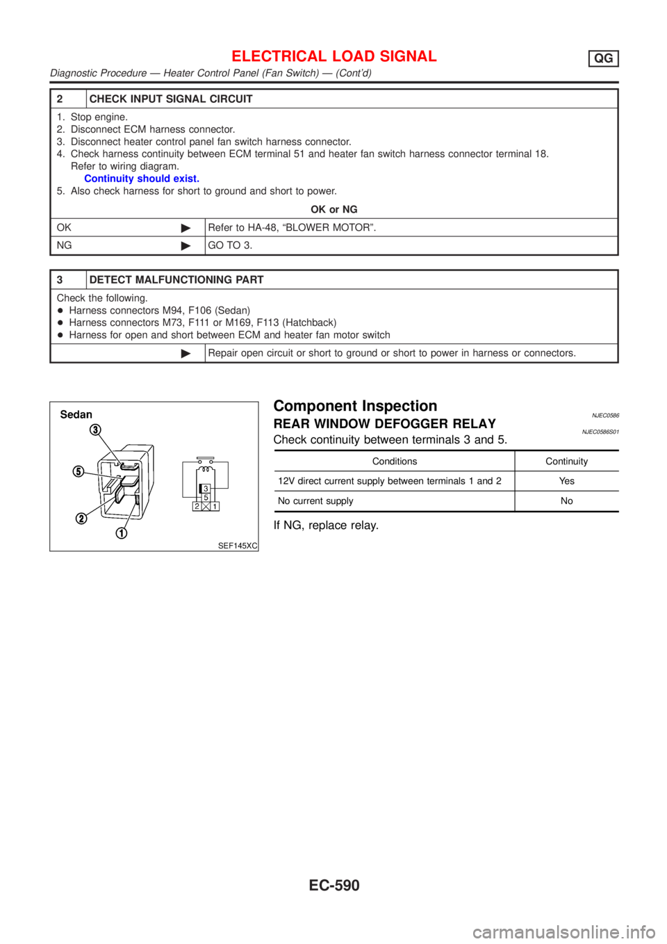
SEF145XC
Component InspectionNJEC0586REAR WINDOW DEFOGGER RELAYNJEC0586S01Check continuity between terminals 3 and 5.
Conditions Continuity
12V direct current supply between terminals 1 and 2 Yes
No current supply No
If NG, replace relay.
ELECTRICAL LOAD SIGNALQG
Diagnostic Procedure Ð Heater Control Panel (Fan Switch) Ð (Cont'd)
EC-590
Page 1315 of 2898
Wiring DiagramNJEC0466SEDAN MODELS AND HATCHBACK MODELS WITH
ECM IN ENGINE COMPARTMENT
NJEC0466S01
HEC894
MI & DATA LINK CONNECTORSQG
Wiring Diagram
EC-591
Page 1316 of 2898
HATCHBACK MODELS WITH ECM IN CABINNJEC0466S02
HEC980
MI & DATA LINK CONNECTORSQG
Wiring Diagram (Cont'd)
EC-592
Page 1325 of 2898
SEF348N
+When measuring ECM signals with a circuit tester, never
allow the two tester probes to contact.
Accidental contact of probes will cause a short circuit and
damage the ECM power transistor.
+Do not use ECM ground terminals when measuring input/
output voltage. Doing so may result in damage to the
ECM's transistor. Use a ground other than ECM terminals,
such as the ground.
+Install the break-out box between ECM and ECM harness
connectors when measuring ECM input/output voltage.
Wiring Diagrams and Trouble DiagnosisNJEC0604When you read Wiring diagrams, refer to the following:
+GI-11, ªHOW TO READ WIRING DIAGRAMSº
+EL-10, ªPOWER SUPPLY ROUTINGº for power distribution circuit
When you perform trouble diagnosis, refer to the following:
+GI-32, ªHOW TO FOLLOW TEST GROUPS IN TROUBLE DIAGNOSESº
+GI-21, ªHOW TO PERFORM EFFICIENT DIAGNOSIS FOR AN ELECTRICAL INCIDENTº
PRECAUTIONSYD
Precautions (Cont'd)
EC-601