Page 1330 of 2898
Circuit DiagramNJEC0608SEDANNJEC0608S01
HEC880
ENGINE AND EMISSION CONTROL OVERALL SYSTEMYD
Circuit Diagram
EC-606
Page 1331 of 2898
HATCHBACKNJEC0608S02
NEF342A
ENGINE AND EMISSION CONTROL OVERALL SYSTEMYD
Circuit Diagram (Cont'd)
EC-607
Page 1332 of 2898
System DiagramNJEC0609
NEF343A
ENGINE AND EMISSION CONTROL OVERALL SYSTEMYD
System Diagram
EC-608
Page 1391 of 2898
WIRING DIAGRAMNJEC0640Sedan Models and Hatchback Models with ECM in Engine CompartmentNJEC0640S01
HEC881
TROUBLE DIAGNOSIS FOR POWER SUPPLYYD
Main Power Supply and Ground Circuit (Cont'd)
EC-667
Page 1393 of 2898

DIAGNOSTIC PROCEDURENJEC0641
1 INSPECTION START
Start engine.
Is engine running?
YesorNo
Ye s©GO TO 13.
No©GO TO 2.
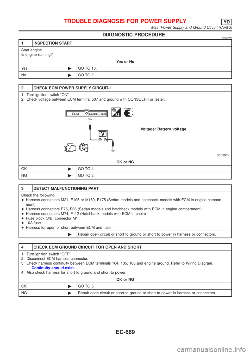
2 CHECK ECM POWER SUPPLY CIRCUIT-I
1. Turn ignition switch ªONº.
2. Check voltage between ECM terminal 507 and ground with CONSULT-II or tester.
SEF895Y
OK or NG
OK©GO TO 4.
NG©GO TO 3.
3 DETECT MALFUNCTIONING PART
Check the following.
+Harness connectors M21, E106 or M160, E175 (Sedan models and hatchback models with ECM in engine compart-
ment)
+Harness connectors E75, F36 (Sedan models and hatchback models with ECM in engine compartment)
+Harness connectors M74, F112 (Hatchback models with ECM in cabin)
+Fuse block (J/B) connector M1
+10A fuse
+Harness for open or short between ECM and fuse
©Repair open circuit or short to ground or short to power in harness or connectors.
4 CHECK ECM GROUND CIRCUIT FOR OPEN AND SHORT
1. Turn ignition switch ªOFFº.
2. Disconnect ECM harness connector.
3. Check harness continuity between ECM terminals 104, 105, 106 and engine ground. Refer to Wiring Diagram.
Continuity should exist.
4. Also check harness for short to ground and short to power.
OK or NG
OK©GO TO 5.
NG©Repair open circuit or short to ground or short to power in harness or connectors.
TROUBLE DIAGNOSIS FOR POWER SUPPLYYD
Main Power Supply and Ground Circuit (Cont'd)
EC-669
Page 1395 of 2898

8 CHECK OUTPUT SIGNAL CIRCUIT FOR OPEN AND SHORT
1. Disconnect ECM harness connector.
2. Check harness continuity between ECM terminal 325 and ECM relay terminal 2. Refer to Wiring Diagram.
Continuity should exist.
3. Also check harness for short to ground and short to power.
OK or NG
OK©GO TO 10.
NG©GO TO 9.
9 DETECT MALFUNCTIONING PART
Check the following.
+Harness connectors E174, M159 (Hatchback models with ECM in cabin)
+Harness connectors M63, F102 (Hatchback models with ECM in cabin)
+Harness for open or short between ECM and ECM relay
©Repair open circuit or short to ground or short to power in harness or connectors.
10 CHECK ECM POWER SUPPLY CIRCUIT-IV
1. Check harness continuity between ECM terminals 107, 108, 109 and ECM relay terminal 7. Refer to Wiring Diagram.
Continuity should exist.
2. Also check harness for short to ground and short to power.
OK or NG
OK©GO TO 12.
NG©GO TO 11.
11 DETECT MALFUNCTIONING PART
Check the following.
+Harness connectors E75, F36 (Hatchback models with ECM in cabin)
+Harness for open or short between ECM and ECM relay
©Repair open circuit or short to ground or short to power in harness or connectors.
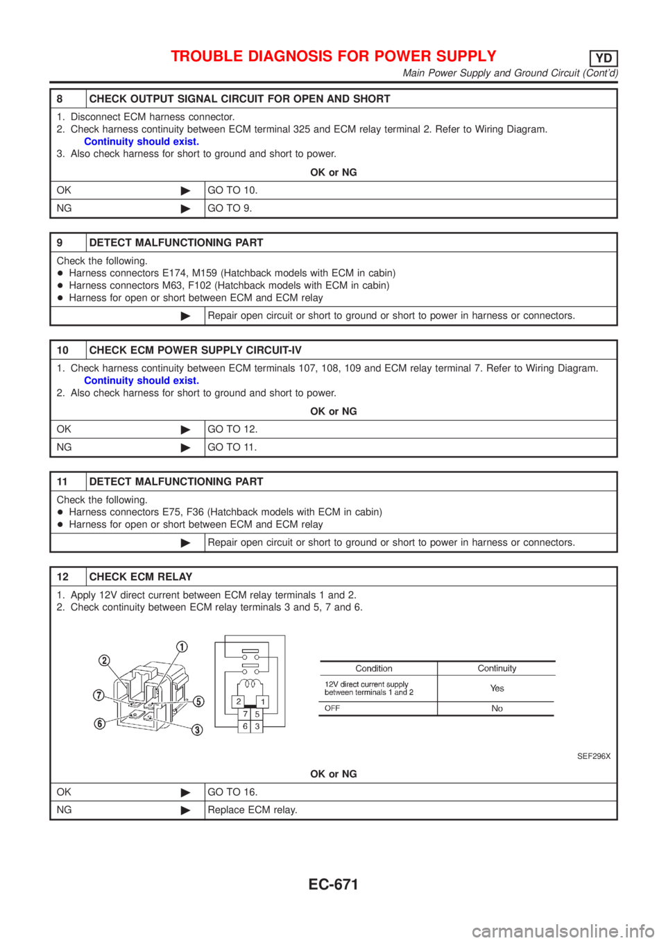
12 CHECK ECM RELAY
1. Apply 12V direct current between ECM relay terminals 1 and 2.
2. Check continuity between ECM relay terminals 3 and 5, 7 and 6.
SEF296X
OK or NG
OK©GO TO 16.
NG©Replace ECM relay.
TROUBLE DIAGNOSIS FOR POWER SUPPLYYD
Main Power Supply and Ground Circuit (Cont'd)
EC-671
Page 1396 of 2898

13 CHECK ECM POWER SUPPLY CIRCUIT-V
1. Turn ignition switch ªOFFº.
2. Disconnect ECM relay. (For ECM relay location, refer to ªEngine Control Component Parts Locationº.)
3. Disconnect ECM harness connector.
4. Check harness continuity between ECM terminals 107, 108, 109 and ECM relay terminal 7. Refer to Wiring Diagram.
Continuity should exist.
5. Also check harness for short to ground and short to power.
OK or NG
OK©GO TO 15.
NG©GO TO 14.
14 DETECT MALFUNCTIONING PART
Check the following.
+Harness connectors E75, F36 (New H/B)
+Harness for open or short between ECM and ECM relay
©Repair open circuit or short to ground or short to power in harness or connectors.
15 CHECK ECM GROUND CIRCUIT FOR OPEN AND SHORT
1. Check harness continuity between ECM terminals 104, 105, 106 and engine ground. Refer to Wiring Diagram.
Continuity should exist.
2. Also check harness for short to ground and short to power.
OK or NG
OK©GO TO 16.
NG©Repair open circuit or short to ground or short to power in harness or connectors.
16 CHECK INTERMITTENT INCIDENT
Refer to ªTROUBLE DIAGNOSIS FOR INTERMITTENT INCIDENTº, EC-665.
©INSPECTION END
TROUBLE DIAGNOSIS FOR POWER SUPPLYYD
Main Power Supply and Ground Circuit (Cont'd)
EC-672
Page 1399 of 2898
Wiring DiagramNJEC0647SEDAN MODELS AND HATCHBACK MODELS WITH ECM IN ENGINE COMPARTMENTNJEC0647S01
HEC883
DTC P0100 MASS AIR FLOW SENYD
Wiring Diagram
EC-675