2001 NISSAN ALMERA air bleeding
[x] Cancel search: air bleedingPage 1341 of 2898
JEF346Y
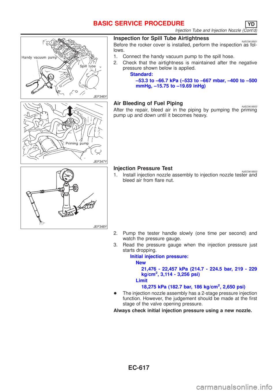
Inspection for Spill Tube AirtightnessNJEC0619S01Before the rocker cover is installed, perform the inspection as fol-
lows.
1. Connect the handy vacuum pump to the spill hose.
2. Check that the airtightness is maintained after the negative
pressure shown below is applied.
Standard:
±53.3 to ±66.7 kPa (±533 to ±667 mbar, ±400 to ±500
mmHg, ±15.75 to ±19.69 inHg)
JEF347Y
Air Bleeding of Fuel PipingNJEC0619S02After the repair, bleed air in the piping by pumping the priming
pump up and down until it becomes heavy.
JEF348Y
Injection Pressure TestNJEC0619S031. Install injection nozzle assembly to injection nozzle tester and
bleed air from flare nut.
2. Pump the tester handle slowly (one time per second) and
watch the pressure gauge.
3. Read the pressure gauge when the injection pressure just
starts dropping.
Initial injection pressure:
New
21,476 - 22,457 kPa (214.7 - 224.5 bar, 219 - 229
kg/cm
2, 3,114 - 3,256 psi)
Limit
18,275 kPa (182.7 bar, 186 kg/cm
2, 2,650 psi)
+The injection nozzle assembly has a 2-stage pressure injection
function. However, the judgement should be made at the first
stage of the valve opening pressure.
Always check initial injection pressure using a new nozzle.
BASIC SERVICE PROCEDUREYD
Injection Tube and Injection Nozzle (Cont'd)
EC-617
Page 1349 of 2898
Fuel Filter
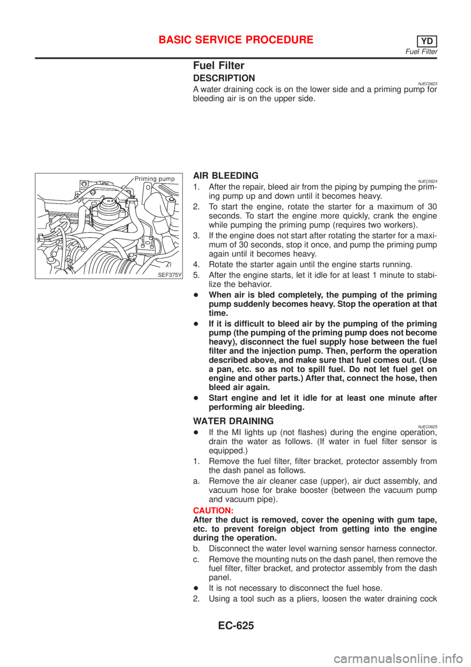
DESCRIPTIONNJEC0623A water draining cock is on the lower side and a priming pump for
bleeding air is on the upper side.
SEF375Y
AIR BLEEDINGNJEC06241. After the repair, bleed air from the piping by pumping the prim-
ing pump up and down until it becomes heavy.
2. To start the engine, rotate the starter for a maximum of 30
seconds. To start the engine more quickly, crank the engine
while pumping the priming pump (requires two workers).
3. If the engine does not start after rotating the starter for a maxi-
mum of 30 seconds, stop it once, and pump the priming pump
again until it becomes heavy.
4. Rotate the starter again until the engine starts running.
5. After the engine starts, let it idle for at least 1 minute to stabi-
lize the behavior.
+When air is bled completely, the pumping of the priming
pump suddenly becomes heavy. Stop the operation at that
time.
+If it is difficult to bleed air by the pumping of the priming
pump (the pumping of the priming pump does not become
heavy), disconnect the fuel supply hose between the fuel
filter and the injection pump. Then, perform the operation
described above, and make sure that fuel comes out. (Use
a pan, etc. so as not to spill fuel. Do not let fuel get on
engine and other parts.) After that, connect the hose, then
bleed air again.
+Start engine and let it idle for at least one minute after
performing air bleeding.
WATER DRAININGNJEC0625+If the MI lights up (not flashes) during the engine operation,
drain the water as follows. (If water in fuel filter sensor is
equipped.)
1. Remove the fuel filter, filter bracket, protector assembly from
the dash panel as follows.
a. Remove the air cleaner case (upper), air duct assembly, and
vacuum hose for brake booster (between the vacuum pump
and vacuum pipe).
CAUTION:
After the duct is removed, cover the opening with gum tape,
etc. to prevent foreign object from getting into the engine
during the operation.
b. Disconnect the water level warning sensor harness connector.
c. Remove the mounting nuts on the dash panel, then remove the
fuel filter, filter bracket, and protector assembly from the dash
panel.
+It is not necessary to disconnect the fuel hose.
2. Using a tool such as a pliers, loosen the water draining cock
BASIC SERVICE PROCEDUREYD
Fuel Filter
EC-625
Page 1350 of 2898
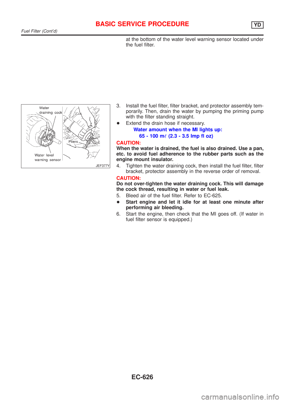
at the bottom of the water level warning sensor located under
the fuel filter.
JEF377Y
3. Install the fuel filter, filter bracket, and protector assembly tem-
porarily. Then, drain the water by pumping the priming pump
with the filter standing straight.
+Extend the drain hose if necessary.
Water amount when the MI lights up:
65 - 100 m!(2.3 - 3.5 Imp fl oz)
CAUTION:
When the water is drained, the fuel is also drained. Use a pan,
etc. to avoid fuel adherence to the rubber parts such as the
engine mount insulator.
4. Tighten the water draining cock, then install the fuel filter, filter
bracket, protector assembly in the reverse order of removal.
CAUTION:
Do not over-tighten the water draining cock. This will damage
the cock thread, resulting in water or fuel leak.
5. Bleed air of the fuel filter. Refer to EC-625.
+Start engine and let it idle for at least one minute after
performing air bleeding.
6. Start the engine, then check that the MI goes off. (If water in
fuel filter sensor is equipped.)
BASIC SERVICE PROCEDUREYD
Fuel Filter (Cont'd)
EC-626
Page 1366 of 2898
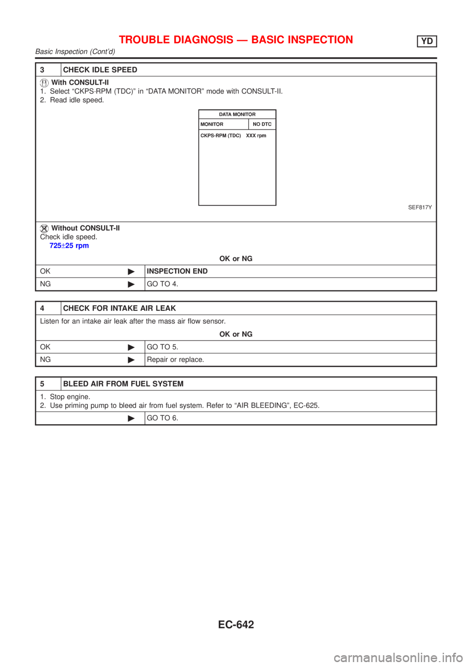
3 CHECK IDLE SPEED
With CONSULT-II
1. Select ªCKPS´RPM (TDC)º in ªDATA MONITORº mode with CONSULT-II.
2. Read idle speed.
SEF817Y
Without CONSULT-II
Check idle speed.
725±25 rpm
OK or NG
OK©INSPECTION END
NG©GO TO 4.
4 CHECK FOR INTAKE AIR LEAK
Listen for an intake air leak after the mass air flow sensor.
OK or NG
OK©GO TO 5.
NG©Repair or replace.
5 BLEED AIR FROM FUEL SYSTEM
1. Stop engine.
2. Use priming pump to bleed air from fuel system. Refer to ªAIR BLEEDINGº, EC-625.
©GO TO 6.
TROUBLE DIAGNOSIS Ð BASIC INSPECTIONYD
Basic Inspection (Cont'd)
EC-642
Page 2242 of 2898
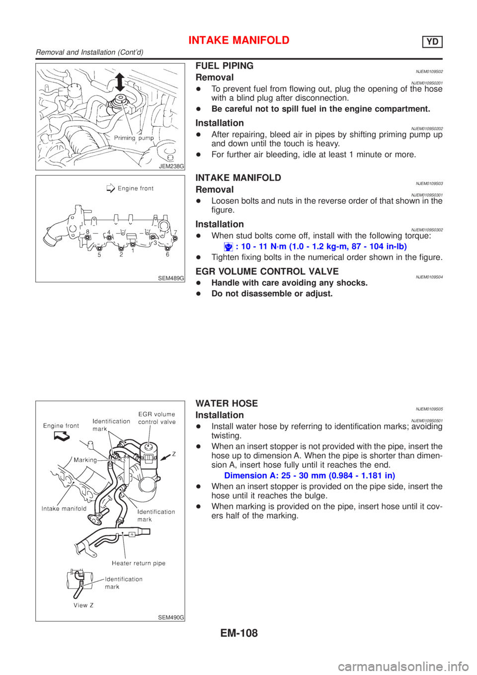
JEM238G
FUEL PIPINGNJEM0109S02RemovalNJEM0109S0201+To prevent fuel from flowing out, plug the opening of the hose
with a blind plug after disconnection.
+Be careful not to spill fuel in the engine compartment.
InstallationNJEM0109S0202+After repairing, bleed air in pipes by shifting priming pump up
and down until the touch is heavy.
+For further air bleeding, idle at least 1 minute or more.
SEM489G
INTAKE MANIFOLDNJEM0109S03RemovalNJEM0109S0301+Loosen bolts and nuts in the reverse order of that shown in the
figure.
InstallationNJEM0109S0302+When stud bolts come off, install with the following torque:
: 10 - 11 N´m (1.0 - 1.2 kg-m, 87 - 104 in-lb)
+Tighten fixing bolts in the numerical order shown in the figure.
EGR VOLUME CONTROL VALVENJEM0109S04+Handle with care avoiding any shocks.
+Do not disassemble or adjust.
SEM490G
WATER HOSENJEM0109S05InstallationNJEM0109S0501+Install water hose by referring to identification marks; avoiding
twisting.
+When an insert stopper is not provided with the pipe, insert the
hose up to dimension A. When the pipe is shorter than dimen-
sion A, insert hose fully until it reaches the end.
Dimension A: 25 - 30 mm (0.984 - 1.181 in)
+When an insert stopper is provided on the pipe side, insert the
hose until it reaches the bulge.
+When marking is provided on the pipe, insert hose until it cov-
ers half of the marking.
INTAKE MANIFOLDYD
Removal and Installation (Cont'd)
EM-108
Page 2325 of 2898
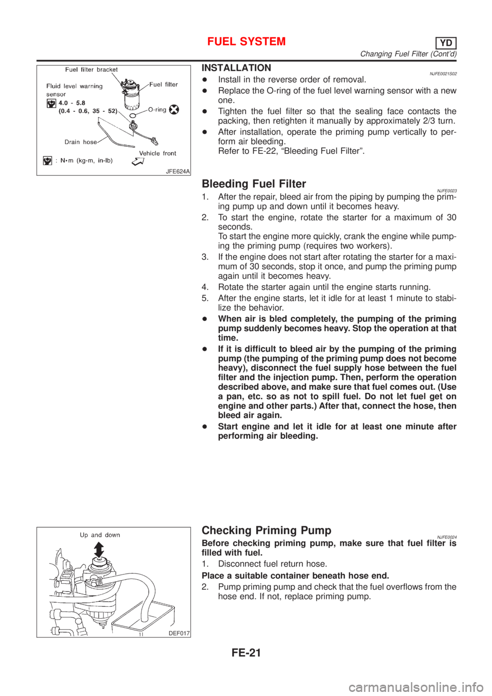
JFE624A
INSTALLATIONNJFE0021S02+Install in the reverse order of removal.
+Replace the O-ring of the fuel level warning sensor with a new
one.
+Tighten the fuel filter so that the sealing face contacts the
packing, then retighten it manually by approximately 2/3 turn.
+After installation, operate the priming pump vertically to per-
form air bleeding.
Refer to FE-22, ªBleeding Fuel Filterº.
Bleeding Fuel FilterNJFE00231. After the repair, bleed air from the piping by pumping the prim-
ing pump up and down until it becomes heavy.
2. To start the engine, rotate the starter for a maximum of 30
seconds.
To start the engine more quickly, crank the engine while pump-
ing the priming pump (requires two workers).
3. If the engine does not start after rotating the starter for a maxi-
mum of 30 seconds, stop it once, and pump the priming pump
again until it becomes heavy.
4. Rotate the starter again until the engine starts running.
5. After the engine starts, let it idle for at least 1 minute to stabi-
lize the behavior.
+When air is bled completely, the pumping of the priming
pump suddenly becomes heavy. Stop the operation at that
time.
+If it is difficult to bleed air by the pumping of the priming
pump (the pumping of the priming pump does not become
heavy), disconnect the fuel supply hose between the fuel
filter and the injection pump. Then, perform the operation
described above, and make sure that fuel comes out. (Use
a pan, etc. so as not to spill fuel. Do not let fuel get on
engine and other parts.) After that, connect the hose, then
bleed air again.
+Start engine and let it idle for at least one minute after
performing air bleeding.
DEF017
Checking Priming PumpNJFE0024Before checking priming pump, make sure that fuel filter is
filled with fuel.
1. Disconnect fuel return hose.
Place a suitable container beneath hose end.
2. Pump priming pump and check that the fuel overflows from the
hose end. If not, replace priming pump.
FUEL SYSTEMYD
Changing Fuel Filter (Cont'd)
FE-21
Page 2500 of 2898
A
A/C HFC134a (R134a) system precaution . HA-2
A/C HFC134a (R134a) system service
procedure .............................................. HA-78
A/C HFC134a (R134a) system service
tools ....................................................... HA-11
A/C HFC134a system service equip-
ment precaution ....................................... HA-6
A/C air flow ............................................... HA-20
A/C component layout .............................. HA-18
A/C compressor clutch removal and
installation .............................................. HA-83
A/C compressor precaution ........................ HA-5
A/C compressor special service tool .......... HA-9
A/C control linkage adjustment
(manual A/C) ......................................... HA-41
A/C control operation (manual A/C) .......... HA-19
A/C diagnostic work flow
(manual A/C) ........................................ HA-33
A/C harness layout (manual A/C) ............. HA-22
A/C lubricant (R134a) ............................... HA-80
A/C operational check ............................... HA-34
A/C performance chart .............................. HA-71
A/C performance test diagnoses .............. HA-69
A/C relay ................................................... HA-66
A/C service data specification .................. HA-97
A/C switch ................................................. HA-67
A/C, M - Wiring diagram ........................... HA-27
A/CCUT - Wiring diagram ....................... EC-830
A/T - Wiring diagram - AT - 1ST .............. AT-207
A/T - Wiring diagram - AT - 2ND ............. AT-214
A/T - Wiring diagram - AT - 3RD ............. AT-220
A/T - Wiring diagram - AT - 4TH .............. AT-227
A/T - Wiring diagram - AT - BA/FTS ....... AT-167,
276
A/T - Wiring diagram - AT - ENG SS ...... AT-173,
201
A/T - Wiring diagram - AT - FTS .............. AT-191
A/T - Wiring diagram - AT - LPSV ... AT-178, 241
A/T - Wiring diagram - AT - MAIN ........... AT-123
A/T - Wiring diagram - AT -
NONDTC .............................................. AT-292
A/T - Wiring diagram - AT -
OVRCSV ...................................... AT-155, 270
A/T - Wiring diagram - AT - PNP/SW ...... AT-185
A/T - Wiring diagram - AT - SSV/A .. AT-144, 248
A/T - Wiring diagram - AT - SSV/B .. AT-150, 254
A/T - Wiring diagram - AT - TCV ..... AT-161, 235
A/T - Wiring diagram - AT - TPS ..... AT-136, 261
A/T - Wiring diagram - AT - VSS/AT ....... AT-128,
197
A/T - Wiring diagram - AT -
VSSMTR ...................................... AT-132, 283
A/T IND - Wiring diagram ........................ EL-195
A/T control ............................................... EC-532
A/T diagnosis communication line .......... EC-434
A/T fluid temperature sensor ................... AT-194A/T shift lock system - Wiring
diagram ................................................ AT-344
A/T shift lock system ................................ AT-343
A/T trouble diagnoses .......................... AT-69, 74
AAC/V - Wiring diagram ................. EC-378, 513
ABS (anti-lock brake system) ................... BR-49
ABS - Wiring diagram ............................... BR-54
ABS sensor rotor ....................................... AX-24
APS - Wiring diagram ............................. EC-685
ATDIAG - Wiring diagram ............... EC-435, 533
Accelerator control system .................... FE-3, 19
Accelerator position sensor .................... EC-685
Air bag disposal ........................................ RS-40
Air bag precautions ...................................... GI-3
Air bag ....................................................... RS-20
Air bleeding (hydraulic clutch) ................... CL-10
Air bleeding for brake system ..................... BR-9
Air conditioner cut control ................. EC-35, 612
Air flow meter - See Mass air flow
sensor .......................................... EC-187, 673
Air mix door control linkage
adjustment ............................................. HA-43
Air spoiler, rear .......................................... BT-47
Alternator ................................................... SC-31
Angular tightening application .............. EM-4, 77
Antenna - See Power antenna ................ EL-282
Anti-lock brake system - Wiring
diagram .................................................. BR-54
Audio and A/C control removal and
installation - See Instrument panel ........ BT-25
Audio ........................................................ EL-258
Automatic transaxle number ...................... GI-41
Auxiliary air control (AAC) valve ..... EC-376, 511
B
Back-up lamp switch (M/T) ....................... MT-21
Back-up lamp ............................................. EL-87
Ball joint (front) .......................................... SU-13
Basic inspection ...................... EC-100, 128, 641
Battery ......................................................... SC-3
Baulk ring (M/T) ............................ MT-31, 55, 93
Blower motor ............................................. HA-54
Blower resistor .......................................... HA-54
Board-on lift ................................................ GI-44
Body alignment .......................................... BT-77
Brake booster ............................................ BR-20
Brake fluid change ...................................... BR-8
Brake fluid level and line check .................. BR-8
Brake hydraulic line .................................. BR-10
Brake master cylinder ............................... BR-14
Brake pedal ............................................... BR-12
Bulb specifications ................................... EL-574
Bumper, front .............................................. BT-7
Bumper, rear .............................................. BT-10
ALPHABETICAL INDEX
IDX-2
Page 2504 of 2898
NVH troubleshooting (SU) ........................ SU-16
NVH troubleshooting (CL) ........................... CL-4
NVIS (Nissan vehicle immobiliser sys-
tem) precautions ....................................... GI-3
Neutral position switch .................... EC-437, 536
O
Oil pan (engine) .................................. EM-20, 89
Oil pressure (engine) ............................ LC-5, 28
Oil pump (A/T) ......................................... AT-384
Oil pump (engine) ................................. LC-5, 28
Oil pump regulator valve (engine) ......... LC-8, 30
Oil seal replacement (engine) .................. EM-32
On board diagnostic system ............. EC-59, 627
Operating cylinder (clutch) ........................ CL-14
Overdrive control switch .......................... AT-341
Overrun clutch .......................................... AT-412
P
P/ANT - Wiring diagram .......................... EL-282
PCV (positive crankcase
ventilation) ..................................... EC-39, 613
PGC/V - Wiring diagram ................. EC-366, 505
PNP/SW - Wiring diagram ...... EC-439, 537, 826
POWER - Wiring diagram ................... EL-11, 28
PST/SW - Wiring diagram ....................... EC-568
Park/Neutral position switch ... EC-437, 536, 826
Park/neutral position switch (A/T) ............ AT-183
Park/neutral position switch (M/T) ............ MT-21
Parking brake control ................................ BR-47
Parking lamp .............................................. EL-81
Piston assembly ............................... EM-62, 155
Piston pin inspection ........................ EM-56, 145
Piston ring inspection ....................... EM-56, 145
Piston to bore clearance .................. EM-58, 147
Power antenna ........................................ EL-282
Power door lock ....................................... EL-314
Power door mirror .................................... EL-294
Power steering fluid level ............................ ST-7
Power steering gear .................................. ST-16
Power steering hydraulic pressure .............. ST-9
Power steering oil pressure switch ......... EC-567
Power steering oil pump ............................ ST-25
Power steering system bleeding ................. ST-8
Power supply routing ................................. EL-10
Power window ......................................... EL-298
Precautions (General) .................................. GI-4
Pressure plate - See Clutch cover ............ CL-22
Priming pump .................................. EC-625, 641
Q
Quick-glow system .................................. EC-806
R
RR02 - Wiring diagram .......... EC-261, 270, 278,
286, 463
RR02/H - Wiring diagram ............... EC-293, 470
Radiator ............................................... LC-16, 42
Radio - See Audio ................................... EL-258
Rear air spoiler .......................................... BT-47
Rear axle (disc brake type) ....................... AX-24
Rear axle ................................................... AX-22
Rear bumper .............................................. BT-10
Rear combination lamp removal and
installation .............................................. BT-47
Rear disc brake .................................. BR-35, 43
Rear door ................................................... BT-16
Rear drum brake ....................................... BR-31
Rear heated oxygen sensor (HO2S)
heater .......................................... EC-291, 469
Rear heated oxygen sensor (HO2S) ..... EC-258,
267, 275, 284, 462
Rear seat belt ............................................ RS-11
Rear seat ................................................... BT-60
Rear suspension ....................................... SU-16
Rear window defogger ............................ EL-240
Rear window .............................................. BT-71
Refrigerant connection precaution .............. HA-3
Refrigerant general precaution ................... HA-2
Refrigerant lines ........................................ HA-91
Refrigeration cycle .................................... HA-13
Release bearing (clutch) ..................... CL-17, 20
Removal and installation (A/T) ................ AT-354
Reverse clutch ......................................... AT-403
Reverse idler shaft (M/T) .............. MT-30, 54, 93
Reverse lamp switch (M/T) - See
Back-up lamp switch (M/T) ................... MT-21
Reverse main gear (M/T) ............. MT-31, 55, 93
Road wheel size ......................................... GI-43
Roof trim .................................................... BT-43
Room lamp - See Interior lamp ............... EL-115
S
S/LOCK - Wiring diagram ............... EL-318, 335,
352, 372
S/SIG - Wiring diagram ........................... EC-558
SAE J1930 terminology list ........................ GI-50
SHIFT - Wiring diagram ........................... AT-344
SROOF - Wiring diagram ........................ EL-292
SRS - See Supplemental Restraint
System ................................................... RS-20
START - Wiring diagram ........................... SC-14
STOP/L - Wiring diagram .................... EL-85, 86
SWL/V - Wiring diagram ................. EC-399, 475
Seal - See Exterior .................................... BT-47
Seat belt pre-tensioner disposal ............... RS-40
Seat belt pre-tensioner ............................... RS-3
Seat belt, front ............................................ RS-5
Seat belt, rear ............................................ RS-11
Seat, front .................................................. BT-56
ALPHABETICAL INDEX
IDX-6