2001 NISSAN ALMERA air bleeding
[x] Cancel search: air bleedingPage 2551 of 2898

JLC298B
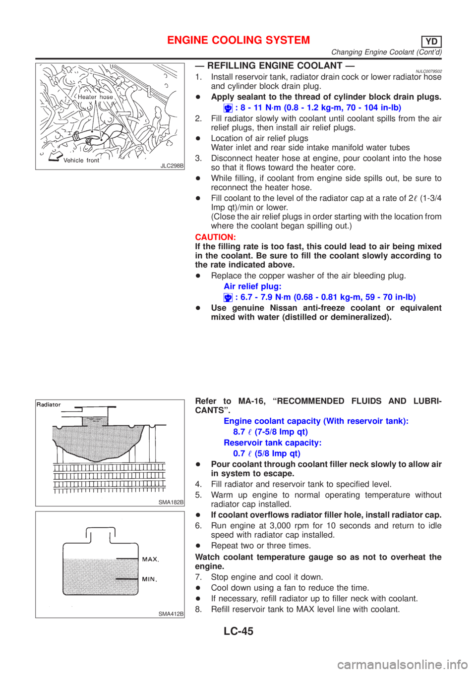
Ð REFILLING ENGINE COOLANT ÐNJLC0079S021. Install reservoir tank, radiator drain cock or lower radiator hose
and cylinder block drain plug.
+Apply sealant to the thread of cylinder block drain plugs.
:8-11N´m(0.8 - 1.2 kg-m, 70 - 104 in-lb)
2. Fill radiator slowly with coolant until coolant spills from the air
relief plugs, then install air relief plugs.
+Location of air relief plugs
Water inlet and rear side intake manifold water tubes
3. Disconnect heater hose at engine, pour coolant into the hose
so that it flows toward the heater core.
+While filling, if coolant from engine side spills out, be sure to
reconnect the heater hose.
+Fill coolant to the level of the radiator cap at a rate of 2!(1-3/4
Imp qt)/min or lower.
(Close the air relief plugs in order starting with the location from
where the coolant began spilling out.)
CAUTION:
If the filling rate is too fast, this could lead to air being mixed
in the coolant. Be sure to fill the coolant slowly according to
the rate indicated above.
+Replace the copper washer of the air bleeding plug.
Air relief plug:
: 6.7 - 7.9 N´m (0.68 - 0.81 kg-m, 59 - 70 in-lb)
+Use genuine Nissan anti-freeze coolant or equivalent
mixed with water (distilled or demineralized).
SMA182B
SMA412B
Refer to MA-16, ªRECOMMENDED FLUIDS AND LUBRI-
CANTSº.
Engine coolant capacity (With reservoir tank):
8.7!(7-5/8 Imp qt)
Reservoir tank capacity:
0.7!(5/8 Imp qt)
+Pour coolant through coolant filler neck slowly to allow air
in system to escape.
4. Fill radiator and reservoir tank to specified level.
5. Warm up engine to normal operating temperature without
radiator cap installed.
+If coolant overflows radiator filler hole, install radiator cap.
6. Run engine at 3,000 rpm for 10 seconds and return to idle
speed with radiator cap installed.
+Repeat two or three times.
Watch coolant temperature gauge so as not to overheat the
engine.
7. Stop engine and cool it down.
+Cool down using a fan to reduce the time.
+If necessary, refill radiator up to filler neck with coolant.
8. Refill reservoir tank to MAX level line with coolant.
ENGINE COOLING SYSTEMYD
Changing Engine Coolant (Cont'd)
LC-45
Page 2837 of 2898

STEERING SYSTEM
SECTION
ST
CONTENTS
PRECAUTIONS...............................................................2
Supplemental Restraint System (SRS)²AIR
BAG²and²SEAT BELT PRE-TENSIONER²...............2
Precautions for Steering System .................................2
PREPARATION...............................................................3
Special Service Tools ..................................................3
Commercial Service Tool .............................................4
NOISE, VIBRATION AND HARSHNESS (NVH)
TROUBLESHOOTING.....................................................5
NVH Troubleshooting Chart.........................................5
ON-VEHICLE SERVICE..................................................6
Checking Steering Wheel Play ....................................6
Checking Neutral Position on Steering Wheel ............6
PRE-CHECKING........................................................6
CHECKING...............................................................6
Front Wheel Turning Angle ..........................................6
Checking Gear Housing Movement ............................6
Checking and Adjusting Drive Belts ............................7
Checking Steering Gear and Linkage .........................7
STEERING GEAR......................................................7
STEERING LINKAGE.................................................7
Checking Fluid Level ...................................................7
Checking Fluid Leakage ..............................................7
Bleeding Hydraulic System..........................................8
Checking Steering Wheel Turning Force ....................8
Checking Hydraulic System.........................................9
STEERING WHEEL AND STEERING COLUMN......... 11
Components............................................................... 11
Removal and Installation ........................................... 11
STEERING WHEEL................................................. 11
STEERING COLUMN...............................................12
Disassembly and Assembly .......................................14
Inspection...................................................................15
TILT MECHANISM...................................................15
POWER STEERING GEAR AND LINKAGE................16
Components...............................................................16
Removal and Installation ...........................................17
Disassembly...............................................................18
Inspection...................................................................19
BOOT.....................................................................19
RACK.....................................................................19
GEAR SUB-ASSEMBLY...........................................19
GEAR HOUSING CYLINDER....................................19
TIE-ROD OUTER AND INNER SOCKETS..................20
Assembly ...................................................................20
Adjustment .................................................................23
POWER STEERING OIL PUMP (QG ENGINE)...........25
Components...............................................................25
Pre-disassembly Inspection .......................................25
Disassembly...............................................................26
Inspection...................................................................27
Assembly ...................................................................27
POWER STEERING OIL PUMP (YD ENGINE)............29
Components...............................................................29
Pre-disassembly Inspection .......................................29
Removal and Installation ...........................................30
Disassembly...............................................................30
Inspection...................................................................31
Assembly ...................................................................32
SERVICE DATA AND SPECIFICATIONS (SDS).........33
General Specifications ...............................................33
Steering Wheel ..........................................................33
Steering Column ........................................................33
Steering Gear and Linkage .......................................34
Power Steering ..........................................................35
Page 2844 of 2898

Bleeding Hydraulic SystemNJST00141. Raise front end of vehicle until wheels are clear of the ground.
2. Add fluid into oil tank to specified level. Then quickly turn steer-
ing wheel fully to right and left and lightly touch steering stop-
pers.
Repeat steering wheel operation until fluid level no longer
decreases.
3. Start engine.
Repeat step 2. above.
+Incomplete air bleeding will cause the following to occur. When
this happens, bleed air again.
a) Air bubbles in reservoir tank
b) Clicking noise in oil pump
c) Excessive buzzing in oil pump
Fluid noise may occur in the valve or oil pump. This is common
when the vehicle is stationary or while turning the steering wheel
slowly. This does not affect the performance or durability of the
system.
SST491B
SST090B
Checking Steering Wheel Turning ForceNJST00151. Park vehicle on a level, dry surface and set parking brake.
2. Start engine.
3. Bring power steering fluid up to adequate operating tempera-
ture. [Make sure temperature of fluid is approximately 60 to
80ÉC (140 to 176ÉF).]
Tires need to be inflated to normal pressure.
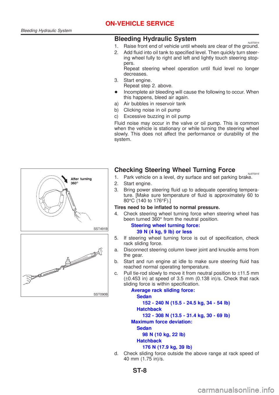
4. Check steering wheel turning force when steering wheel has
been turned 360É from the neutral position.
Steering wheel turning force:
39 N (4 kg, 9 lb) or less
5. If steering wheel turning force is out of specification, check
rack sliding force.
a. Disconnect steering column lower joint and knuckle arms from
the gear.
b. Start and run engine at idle to make sure steering fluid has
reached normal operating temperature.
c. Pull tie-rod slowly to move it from neutral position to±11.5 mm
(±0.453 in) at speed of 3.5 mm (0.138 in)/s. Check that rack
sliding force is within specification.
Average rack sliding force:
Sedan
152 - 240 N (15.5 - 24.5 kg, 34 - 54 lb)
Hatchback
132 - 308 N (13.5 - 31.4 kg, 30 - 69 lb)
Maximum force deviation:
Sedan
98 N (10 kg, 22 lb)
Hatchback
176 N (17.9 kg, 39 lb)
d. Check sliding force outside the above range at rack speed of
40 mm (1.75 in)/s.
ON-VEHICLE SERVICE
Bleeding Hydraulic System
ST-8