Page 586 of 2898
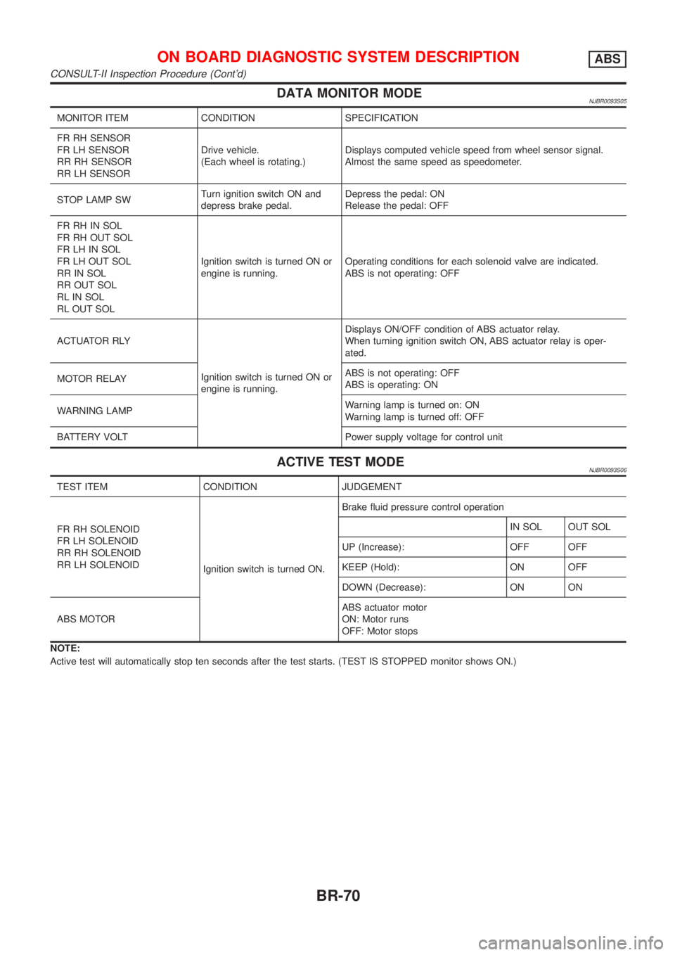
DATA MONITOR MODENJBR0093S05
MONITOR ITEM CONDITION SPECIFICATION
FR RH SENSOR
FR LH SENSOR
RR RH SENSOR
RR LH SENSORDrive vehicle.
(Each wheel is rotating.)Displays computed vehicle speed from wheel sensor signal.
Almost the same speed as speedometer.
STOP LAMP SWTurn ignition switch ON and
depress brake pedal.Depress the pedal: ON
Release the pedal: OFF
FR RH IN SOL
FR RH OUT SOL
FR LH IN SOL
FR LH OUT SOL
RR IN SOL
RR OUT SOL
RL IN SOL
RL OUT SOLIgnition switch is turned ON or
engine is running.Operating conditions for each solenoid valve are indicated.
ABS is not operating: OFF
ACTUATOR RLY
Ignition switch is turned ON or
engine is running.Displays ON/OFF condition of ABS actuator relay.
When turning ignition switch ON, ABS actuator relay is oper-
ated.
MOTOR RELAYABS is not operating: OFF
ABS is operating: ON
WARNING LAMPWarning lamp is turned on: ON
Warning lamp is turned off: OFF
BATTERY VOLT Power supply voltage for control unit
ACTIVE TEST MODENJBR0093S06
TEST ITEM CONDITION JUDGEMENT
FR RH SOLENOID
FR LH SOLENOID
RR RH SOLENOID
RR LH SOLENOID
Ignition switch is turned ON.Brake fluid pressure control operation
IN SOL OUT SOL
UP (Increase): OFF OFF
KEEP (Hold): ON OFF
DOWN (Decrease): ON ON
ABS MOTORABS actuator motor
ON: Motor runs
OFF: Motor stops
NOTE:
Active test will automatically stop ten seconds after the test starts. (TEST IS STOPPED monitor shows ON.)
ON BOARD DIAGNOSTIC SYSTEM DESCRIPTIONABS
CONSULT-II Inspection Procedure (Cont'd)
BR-70
Page 590 of 2898
5 RECHECK BRAKE FLUID LEVEL
Check brake fluid level in reservoir tank again.
SBR451D
Is brake fluid filled between MAX and MIN lines on reservoir tank and/or has brake fluid been contaminated?
Ye s©GO TO 6.
No©Fill up brake fluid.
6 CHECK WARNING LAMP ACTIVATION
Check warning lamp activation.
SBR759E
Does warning lamp turn on when ignition switch is turned ªONº?
Ye s©GO TO 7.
No©Check fuse, warning lamp bulb and warning lamp circuit.
7 CHECK WARNING LAMP DEACTIVATION
Check warning lamp for deactivation after engine is started.
Does warning lamp turn off when engine is started?
Ye s©GO TO 8.
No©Go to Self-diagnosis. Refer to BR-63, 65.
8 DRIVE VEHICLE
Drive vehicle at speeds over 30 km/h (19 MPH) for at least one minute.
Does warning lamp remain off after vehicle has been driven at 30 km/h (19 MPH) for at least one minute?
Ye s©END
No©Go to Self-diagnosis. Refer to BR-63, 65.
TROUBLE DIAGNOSIS Ð BASIC INSPECTIONABS
Preliminary Check (Cont'd)
BR-74
Page 592 of 2898
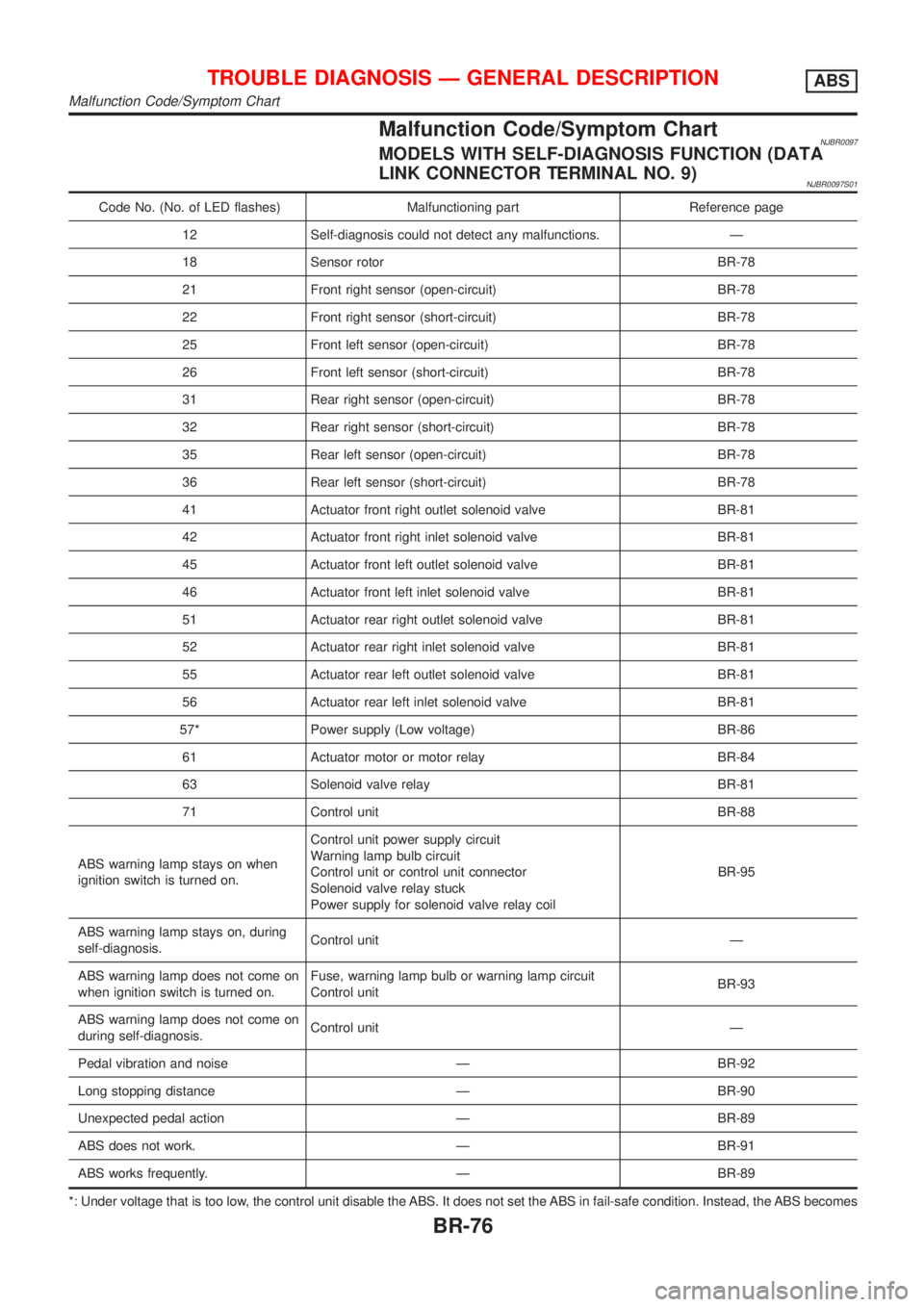
Malfunction Code/Symptom ChartNJBR0097MODELS WITH SELF-DIAGNOSIS FUNCTION (DATA
LINK CONNECTOR TERMINAL NO. 9)
NJBR0097S01
Code No. (No. of LED flashes) Malfunctioning part Reference page
12 Self-diagnosis could not detect any malfunctions. Ð
18 Sensor rotor BR-78
21 Front right sensor (open-circuit) BR-78
22 Front right sensor (short-circuit) BR-78
25 Front left sensor (open-circuit) BR-78
26 Front left sensor (short-circuit) BR-78
31 Rear right sensor (open-circuit) BR-78
32 Rear right sensor (short-circuit) BR-78
35 Rear left sensor (open-circuit) BR-78
36 Rear left sensor (short-circuit) BR-78
41 Actuator front right outlet solenoid valve BR-81
42 Actuator front right inlet solenoid valve BR-81
45 Actuator front left outlet solenoid valve BR-81
46 Actuator front left inlet solenoid valve BR-81
51 Actuator rear right outlet solenoid valve BR-81
52 Actuator rear right inlet solenoid valve BR-81
55 Actuator rear left outlet solenoid valve BR-81
56 Actuator rear left inlet solenoid valve BR-81
57* Power supply (Low voltage) BR-86
61 Actuator motor or motor relay BR-84
63 Solenoid valve relay BR-81
71 Control unit BR-88
ABS warning lamp stays on when
ignition switch is turned on.Control unit power supply circuit
Warning lamp bulb circuit
Control unit or control unit connector
Solenoid valve relay stuck
Power supply for solenoid valve relay coilBR-95
ABS warning lamp stays on, during
self-diagnosis.Control unit Ð
ABS warning lamp does not come on
when ignition switch is turned on.Fuse, warning lamp bulb or warning lamp circuit
Control unitBR-93
ABS warning lamp does not come on
during self-diagnosis.Control unit Ð
Pedal vibration and noise Ð BR-92
Long stopping distance Ð BR-90
Unexpected pedal action Ð BR-89
ABS does not work. Ð BR-91
ABS works frequently. Ð BR-89
*: Under voltage that is too low, the control unit disable the ABS. It does not set the ABS in fail-safe condition. Instead, the ABS becomes
TROUBLE DIAGNOSIS Ð GENERAL DESCRIPTIONABS
Malfunction Code/Symptom Chart
BR-76
Page 598 of 2898
4 CHECK CONNECTOR
1. Disconnect ABS actuator and electric unit connector. Check terminals for damage or loose connection. Then reconnect
connector.
2. Carry out self-diagnosis again.
Does warning lamp activate again?
Ye s©GO TO 5.
No©INSPECTION END
5 CHECK GROUND CIRCUIT
Refer to ABS ACTUATOR AND ELECTRIC UNIT in Ground Circuit Check, BR-75.
Is ground circuit OK?
Ye s©GO TO 6.
No©Repair harness and connectors.
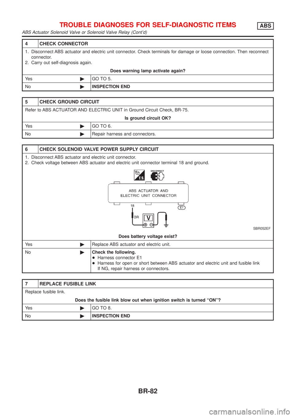
6 CHECK SOLENOID VALVE POWER SUPPLY CIRCUIT
1. Disconnect ABS actuator and electric unit connector.
2. Check voltage between ABS actuator and electric unit connector terminal 18 and ground.
SBR052EF
Does battery voltage exist?
Ye s©Replace ABS actuator and electric unit.
No©Check the following.
+Harness connector E1
+Harness for open or short between ABS actuator and electric unit and fusible link
If NG, repair harness or connectors.
7 REPLACE FUSIBLE LINK
Replace fusible link.
Does the fusible link blow out when ignition switch is turned ªONº?
Ye s©GO TO 8.
No©INSPECTION END
TROUBLE DIAGNOSES FOR SELF-DIAGNOSTIC ITEMSABS
ABS Actuator Solenoid Valve or Solenoid Valve Relay (Cont'd)
BR-82
Page 599 of 2898
8 CHECK RELAY UNIT POWER SUPPLY CIRCUIT
1. Disconnect ABS actuator and electric unit connector.
2. Check continuity between ABS actuator and electric unit connector terminal 18 and ground.
SBR052EF
Does continuity exist?
Ye s©Replace ABS actuator and electric unit.
No©Check the following.
+Harness connector E1
+Harness for open or short between ABS actuator and electric unit and fusible link
If NG, repair harness or connectors.
9 REPLACE FUSE
Replace fuse.
Does the fuse blow out when ignition switch is turned ªONº?
Ye s©Check the following.
+Harness connector E1
+Harness for open or short between ABS actuator and electric unit and fuse
If NG, repair harness or connectors.
No©INSPECTION END
TROUBLE DIAGNOSES FOR SELF-DIAGNOSTIC ITEMSABS
ABS Actuator Solenoid Valve or Solenoid Valve Relay (Cont'd)
BR-83
Page 601 of 2898
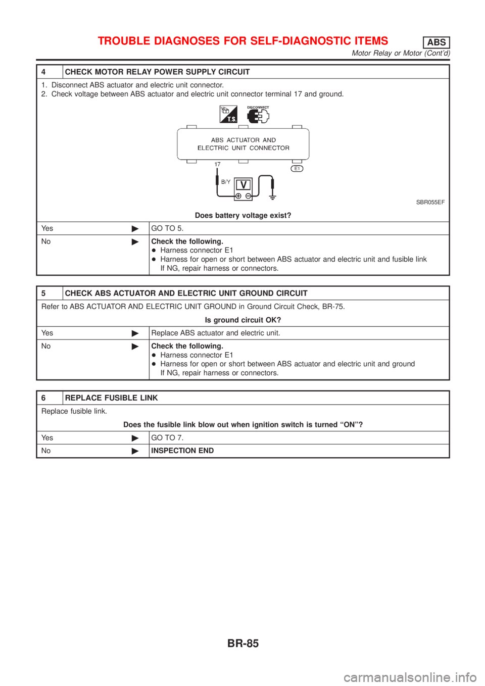
4 CHECK MOTOR RELAY POWER SUPPLY CIRCUIT
1. Disconnect ABS actuator and electric unit connector.
2. Check voltage between ABS actuator and electric unit connector terminal 17 and ground.
SBR055EF
Does battery voltage exist?
Ye s©GO TO 5.
No©Check the following.
+Harness connector E1
+Harness for open or short between ABS actuator and electric unit and fusible link
If NG, repair harness or connectors.
5 CHECK ABS ACTUATOR AND ELECTRIC UNIT GROUND CIRCUIT
Refer to ABS ACTUATOR AND ELECTRIC UNIT GROUND in Ground Circuit Check, BR-75.
Is ground circuit OK?
Ye s©Replace ABS actuator and electric unit.
No©Check the following.
+Harness connector E1
+Harness for open or short between ABS actuator and electric unit and ground
If NG, repair harness or connectors.
6 REPLACE FUSIBLE LINK
Replace fusible link.
Does the fusible link blow out when ignition switch is turned ªONº?
Ye s©GO TO 7.
No©INSPECTION END
TROUBLE DIAGNOSES FOR SELF-DIAGNOSTIC ITEMSABS
Motor Relay or Motor (Cont'd)
BR-85
Page 603 of 2898
2 CHECK CONNECTOR
1. Disconnect ABS actuator and electric unit connector. Check terminals for damage or loose connections. Then recon-
nect connector.
2. Carry out self-diagnosis again.
Does warning lamp activate again?
Ye s©GO TO 3.
No©INSPECTION END
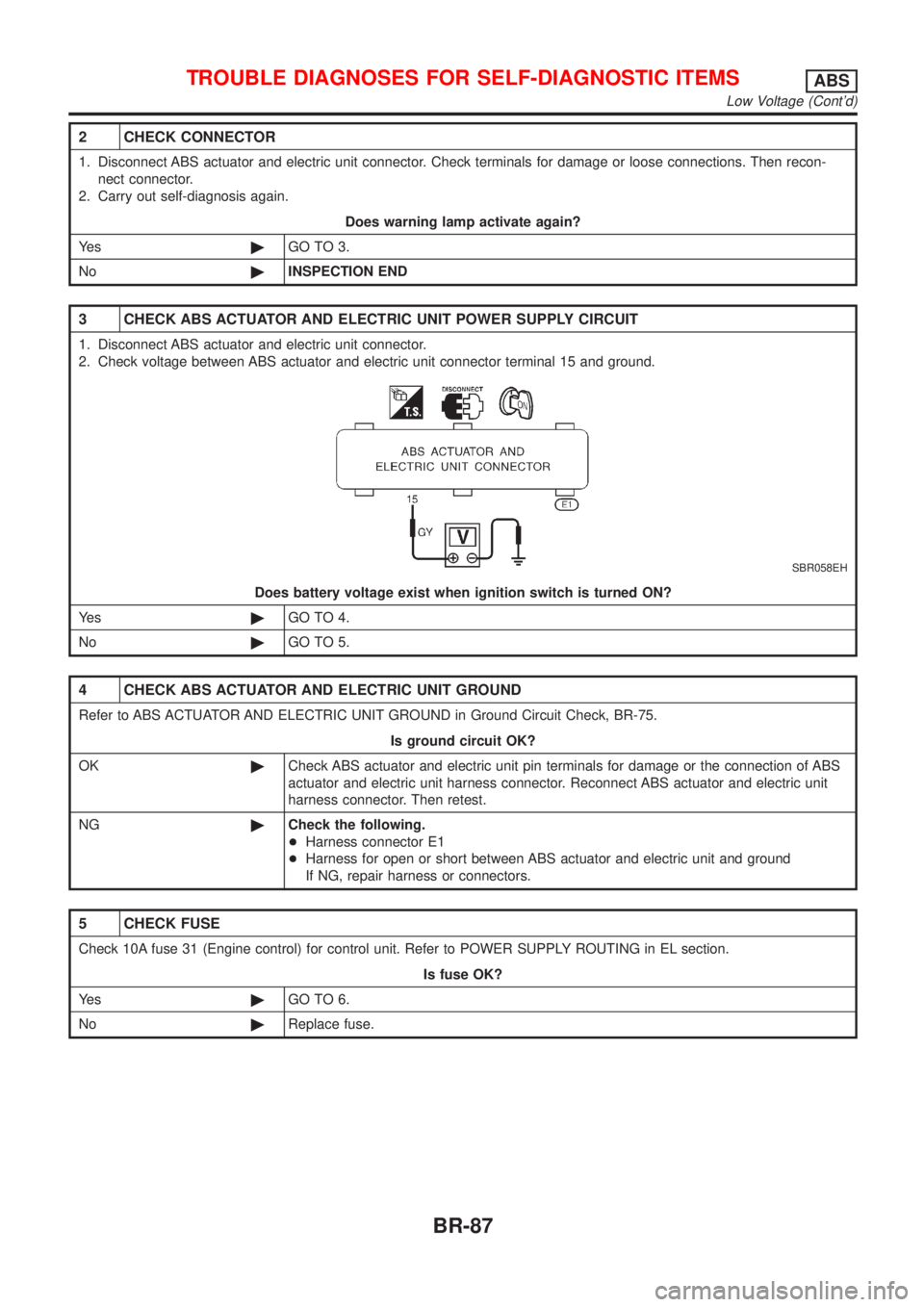
3 CHECK ABS ACTUATOR AND ELECTRIC UNIT POWER SUPPLY CIRCUIT
1. Disconnect ABS actuator and electric unit connector.
2. Check voltage between ABS actuator and electric unit connector terminal 15 and ground.
SBR058EH
Does battery voltage exist when ignition switch is turned ON?
Ye s©GO TO 4.
No©GO TO 5.
4 CHECK ABS ACTUATOR AND ELECTRIC UNIT GROUND
Refer to ABS ACTUATOR AND ELECTRIC UNIT GROUND in Ground Circuit Check, BR-75.
Is ground circuit OK?
OK©Check ABS actuator and electric unit pin terminals for damage or the connection of ABS
actuator and electric unit harness connector. Reconnect ABS actuator and electric unit
harness connector. Then retest.
NG©Check the following.
+Harness connector E1
+Harness for open or short between ABS actuator and electric unit and ground
If NG, repair harness or connectors.
5 CHECK FUSE
Check 10A fuse 31 (Engine control) for control unit. Refer to POWER SUPPLY ROUTING in EL section.
Is fuse OK?
Ye s©GO TO 6.
No©Replace fuse.
TROUBLE DIAGNOSES FOR SELF-DIAGNOSTIC ITEMSABS
Low Voltage (Cont'd)
BR-87
Page 604 of 2898
6 CHECK ABS ACTUATOR AND ELECTRIC UNIT POWER SUPPLY CIRCUIT
Check continuity between battery and ABS actuator and electric unit connector terminal 15.
Does continuity exist?
Ye s©Check battery. Refer to BATTERY in EL section.
No©Check the following.
+Harness connector E1
+Harness for open or short between ABS actuator and electric unit and fuse
If NG, repair harness or connectors.
Control UnitNJBR0103DIAGNOSTIC PROCEDURENJBR0103S01(Malfunction code No. 71 for models with self-diagnosis func-
tion)
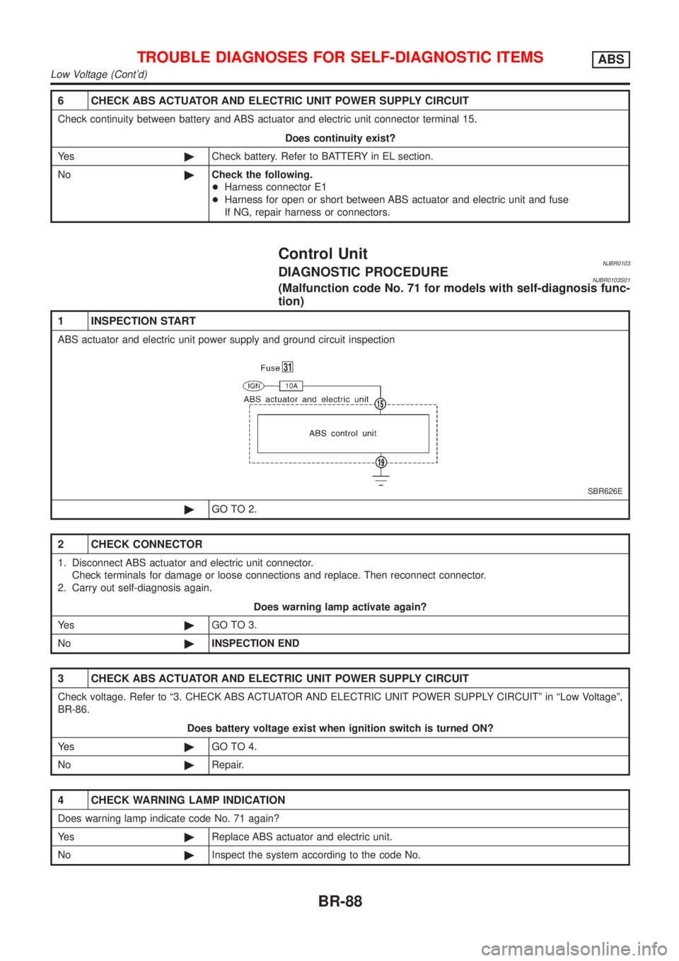
1 INSPECTION START
ABS actuator and electric unit power supply and ground circuit inspection
SBR626E
©GO TO 2.
2 CHECK CONNECTOR
1. Disconnect ABS actuator and electric unit connector.
Check terminals for damage or loose connections and replace. Then reconnect connector.
2. Carry out self-diagnosis again.
Does warning lamp activate again?
Ye s©GO TO 3.
No©INSPECTION END
3 CHECK ABS ACTUATOR AND ELECTRIC UNIT POWER SUPPLY CIRCUIT
Check voltage. Refer to ª3. CHECK ABS ACTUATOR AND ELECTRIC UNIT POWER SUPPLY CIRCUITº in ªLow Voltageº,
BR-86.
Does battery voltage exist when ignition switch is turned ON?
Ye s©GO TO 4.
No©Repair.
4 CHECK WARNING LAMP INDICATION
Does warning lamp indicate code No. 71 again?
Ye s©Replace ABS actuator and electric unit.
No©Inspect the system according to the code No.
TROUBLE DIAGNOSES FOR SELF-DIAGNOSTIC ITEMSABS
Low Voltage (Cont'd)
BR-88