2001 NISSAN ALMERA ignition
[x] Cancel search: ignitionPage 609 of 2898
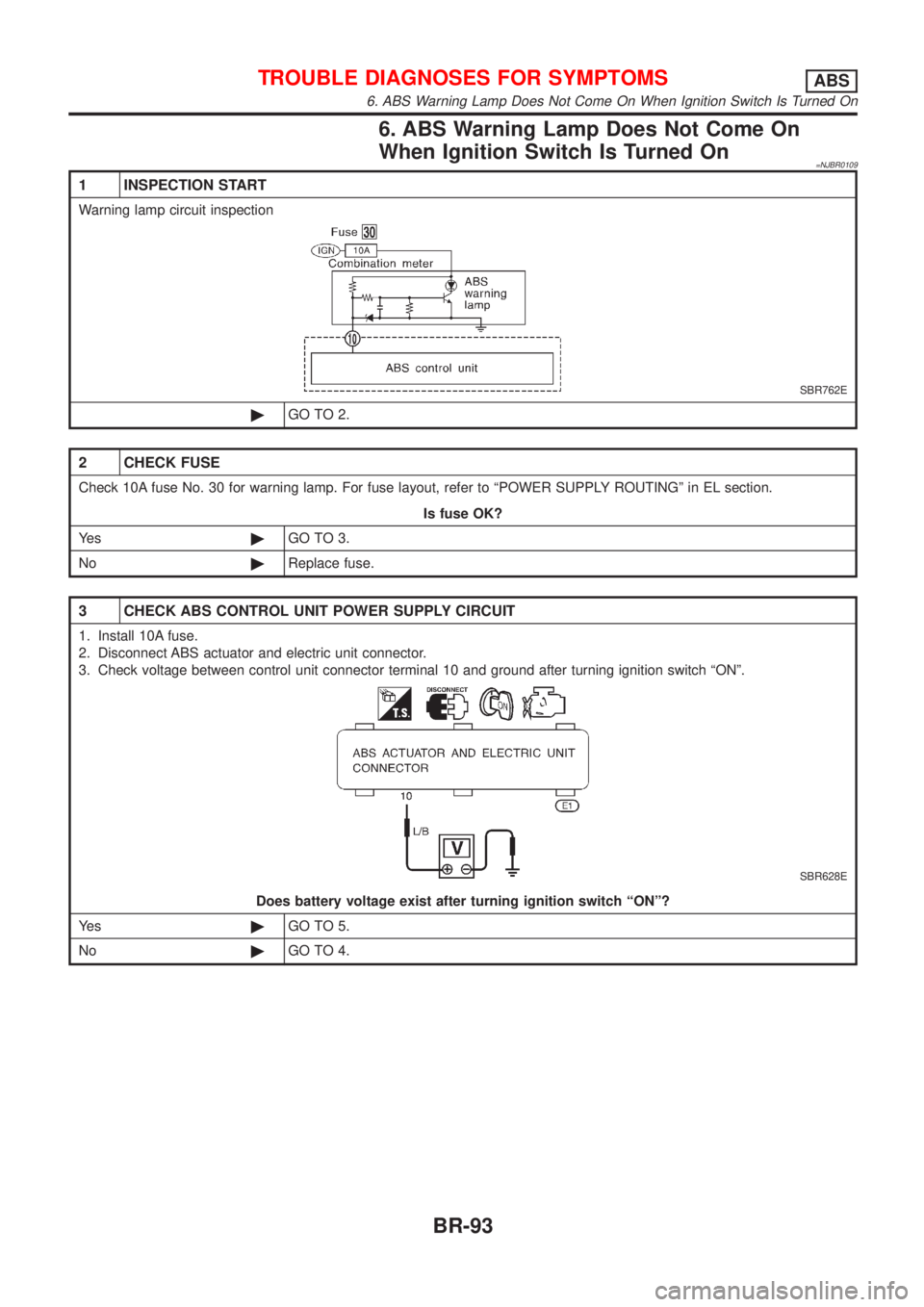
6. ABS Warning Lamp Does Not Come On
When Ignition Switch Is Turned On
=NJBR0109
1 INSPECTION START
Warning lamp circuit inspection
SBR762E
©GO TO 2.
2 CHECK FUSE
Check 10A fuse No. 30 for warning lamp. For fuse layout, refer to ªPOWER SUPPLY ROUTINGº in EL section.
Is fuse OK?
Ye s©GO TO 3.
No©Replace fuse.
3 CHECK ABS CONTROL UNIT POWER SUPPLY CIRCUIT
1. Install 10A fuse.
2. Disconnect ABS actuator and electric unit connector.
3. Check voltage between control unit connector terminal 10 and ground after turning ignition switch ªONº.
SBR628E
Does battery voltage exist after turning ignition switch ªONº?
Ye s©GO TO 5.
No©GO TO 4.
TROUBLE DIAGNOSES FOR SYMPTOMSABS
6. ABS Warning Lamp Does Not Come On When Ignition Switch Is Turned On
BR-93
Page 610 of 2898
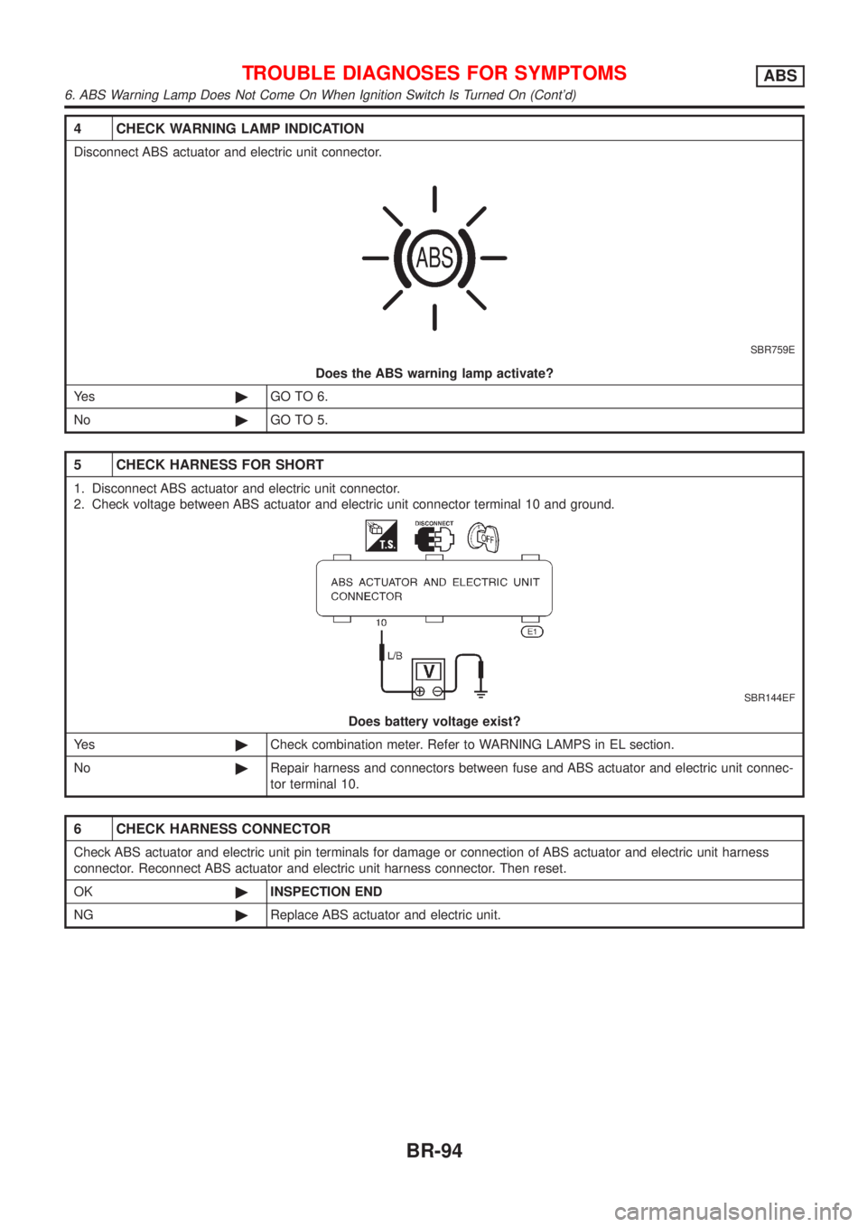
4 CHECK WARNING LAMP INDICATION
Disconnect ABS actuator and electric unit connector.
SBR759E
Does the ABS warning lamp activate?
Ye s©GO TO 6.
No©GO TO 5.
5 CHECK HARNESS FOR SHORT
1. Disconnect ABS actuator and electric unit connector.
2. Check voltage between ABS actuator and electric unit connector terminal 10 and ground.
SBR144EF
Does battery voltage exist?
Ye s©Check combination meter. Refer to WARNING LAMPS in EL section.
No©Repair harness and connectors between fuse and ABS actuator and electric unit connec-
tor terminal 10.
6 CHECK HARNESS CONNECTOR
Check ABS actuator and electric unit pin terminals for damage or connection of ABS actuator and electric unit harness
connector. Reconnect ABS actuator and electric unit harness connector. Then reset.
OK©INSPECTION END
NG©Replace ABS actuator and electric unit.
TROUBLE DIAGNOSES FOR SYMPTOMSABS
6. ABS Warning Lamp Does Not Come On When Ignition Switch Is Turned On (Cont'd)
BR-94
Page 611 of 2898
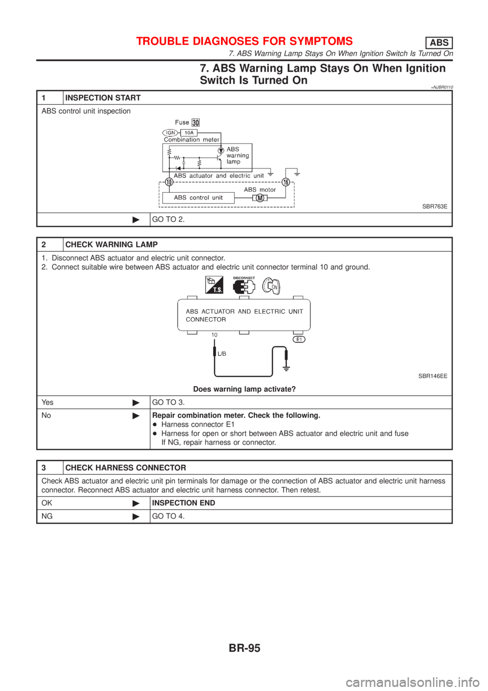
7. ABS Warning Lamp Stays On When Ignition
Switch Is Turned On
=NJBR0110
1 INSPECTION START
ABS control unit inspection
SBR763E
©GO TO 2.
2 CHECK WARNING LAMP
1. Disconnect ABS actuator and electric unit connector.
2. Connect suitable wire between ABS actuator and electric unit connector terminal 10 and ground.
SBR146EE
Does warning lamp activate?
Ye s©GO TO 3.
No©Repair combination meter. Check the following.
+Harness connector E1
+Harness for open or short between ABS actuator and electric unit and fuse
If NG, repair harness or connector.
3 CHECK HARNESS CONNECTOR
Check ABS actuator and electric unit pin terminals for damage or the connection of ABS actuator and electric unit harness
connector. Reconnect ABS actuator and electric unit harness connector. Then retest.
OK©INSPECTION END
NG©GO TO 4.
TROUBLE DIAGNOSES FOR SYMPTOMSABS
7. ABS Warning Lamp Stays On When Ignition Switch Is Turned On
BR-95
Page 612 of 2898
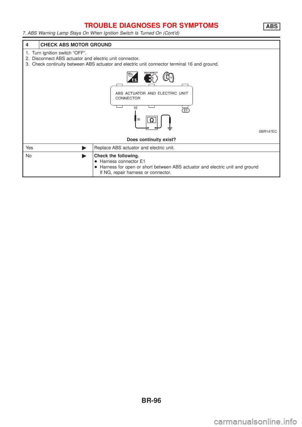
4 CHECK ABS MOTOR GROUND
1. Turn ignition switch ªOFFº.
2. Disconnect ABS actuator and electric unit connector.
3. Check continuity between ABS actuator and electric unit connector terminal 16 and ground.
SBR147EC
Does continuity exist?
Ye s©Replace ABS actuator and electric unit.
No©Check the following.
+Harness connector E1
+Harness for open or short between ABS actuator and electric unit and ground
If NG, repair harness or connector.
TROUBLE DIAGNOSES FOR SYMPTOMSABS
7. ABS Warning Lamp Stays On When Ignition Switch Is Turned On (Cont'd)
BR-96
Page 674 of 2898
Removal and InstallationNJBT0018+When removing or installing the seat trim, carefully handle it to keep dirt out and avoid damage.
HFor Wiring Diagram, refer to EL-288, ªWiring Diagram Ð HEATED SEAT к.
CAUTION:
+Before removing the front seat, turn the ignition switch off, disconnect both battery cables and wait
at least 3 minutes.
+Do not drop, tilt, or bump the side air bag module installed in the seat. Always handle it with care.
+Disconnect the side air bag harness connector and heated seat harness connector from under the
seat before removing the seat.
+Disconnect the side air bag harness connector before removing the seat back. Refer to RS-36,
ªFront Side Air Bag Moduleº for details.
FRONT SEAT
Removal and Installation
BT-56
Page 725 of 2898
ENGINE CONTROL SYSTEM
SECTION
EC
CONTENTS
QG
TROUBLE DIAGNOSIS - INDEX..................................10
Alphabetical & P No. Index for DTC .........................10
PRECAUTIONS.............................................................16
Supplemental Restraint System (SRS)²AIR
BAG²and²SEAT BELT PRE-TENSIONER².............16
Precautions for On Board Diagnostic (OBD)
System of Engine and A/T.........................................16
Engine Fuel & Emission Control System ..................17
Wiring Diagrams and Trouble Diagnosis ...................19
PREPARATION.............................................................20
Special Service Tools ................................................20
Commercial Service Tools .........................................20
ENGINE AND EMISSION CONTROL OVERALL
SYSTEM.........................................................................21
Engine Control Component Parts Location ...............21
Circuit Diagram ..........................................................25
System Diagram ........................................................29
Vacuum Hose Drawing ..............................................30
System Chart .............................................................31
ENGINE AND EMISSION BASIC CONTROL
SYSTEM DESCRIPTION...............................................32
Multiport Fuel Injection (MFI) System .......................32
Electronic Ignition (EI) System ..................................34
Air Conditioning Cut Control ......................................35
Fuel Cut Control (at no load & high engine
speed) ........................................................................36
Evaporative Emission System ...................................36
Positive Crankcase Ventilation ..................................39
BASIC SERVICE PROCEDURE...................................40
Fuel Pressure Release ..............................................40
Fuel Pressure Check .................................................40
Fuel Pressure Regulator Check ................................41
Injector .......................................................................41
How to Check Idle Speed and Ignition Timing ..........43
Preparation ................................................................44
Inspection Procedure .................................................47
Idle Air Volume Learning ...........................................57ON BOARD DIAGNOSTIC SYSTEM
DESCRIPTION...............................................................59
Introduction ................................................................59
Two Trip Detection Logic ...........................................59
Emission-related Diagnostic Information ...................60
NATS (Nissan Anti-theft System) ..............................74
Malfunction Indicator (MI) ..........................................74
OBD System Operation Chart (With Euro-OBD
Models Only)..............................................................78
CONSULT-II ...............................................................83
Generic Scan Tool (GST) ..........................................94
TROUBLE DIAGNOSIS - INTRODUCTION..................96
Introduction ................................................................96
Work Flow ..................................................................98
TROUBLE DIAGNOSIS - BASIC INSPECTION.........100
Basic Inspection/Sedan ...........................................100
Basic Inspection/Hatchback.....................................128
TROUBLE DIAGNOSIS - GENERAL
DESCRIPTION.............................................................153
DTC Inspection Priority Chart..................................153
Fail-safe Chart .........................................................154
Symptom Matrix Chart .............................................155
CONSULT-II Reference Value in Data Monitor
Mode ........................................................................159
Major Sensor Reference Graph in Data Monitor
Mode ........................................................................161
ECM Terminals and Reference Value .....................164
TROUBLE DIAGNOSIS - SPECIFICATION VALUE..173
Description ...............................................................173
Testing Condition .....................................................173
Inspection Procedure ...............................................173
Diagnostic Procedure ..............................................174
TROUBLE DIAGNOSIS FOR INTERMITTENT
INCIDENT.....................................................................177
Description ...............................................................177
Diagnostic Procedure ..............................................177
TROUBLE DIAGNOSIS FOR POWER SUPPLY........178
Main Power Supply and Ground Circuit ..................178
Page 730 of 2898
Diagnostic Procedure ..............................................487
Component Inspection .............................................490
EGR VOLUME CONTROL SYSTEM (WHERE
FITTED)........................................................................491
Description ...............................................................491
CONSULT-II Reference Value in Data Monitor
Mode ........................................................................492
ECM Terminals and Reference Value .....................493
Wiring Diagram ........................................................494
Diagnostic Procedure ..............................................496
Component Inspection .............................................501
EVAP CANISTER PURGE VOLUME CONTROL
SOLENOID VALVE......................................................503
Description ...............................................................503
CONSULT-II Reference Value in Data Monitor
Mode ........................................................................503
ECM Terminals and Reference Value .....................504
Wiring Diagram ........................................................505
Diagnostic Procedure ..............................................507
Component Inspection .............................................510
IDLE AIR CONTROL VALVE (IACV) - AUXILIARY
AIR CONTROL............................................................ 511
Description ............................................................... 511
CONSULT-II Reference Value in Data Monitor
Mode ........................................................................512
ECM Terminals and Reference Value .....................512
Wiring Diagram ........................................................513
Diagnostic Procedure ..............................................515
Component Inspection .............................................519
CLOSED THROTTLE POSITION SWITCH
(WHERE FITTED)........................................................520
Component Description ...........................................520
ECM Terminals and Reference Value .....................520
Wiring Diagram ........................................................521
Diagnostic Procedure ..............................................522
Component Inspection .............................................525
INTAKE VALVE TIMING CONTROL SOLENOID
VALVE..........................................................................526
Component Description ...........................................526
Operation .................................................................526
CONSULT-II Reference Value in Data Monitor
Mode ........................................................................526
ECM Terminals and Reference Value .....................526
Wiring Diagram ........................................................527
Diagnostic Procedure ..............................................529
Component Inspection .............................................531
A/T COMMUNICATION LINE......................................532
System Description ..................................................532
Wiring Diagram ........................................................533
Diagnostic Procedure ..............................................534
PARK/NEUTRAL POSITION (PNP) SWITCH............536
Component Description ...........................................536CONSULT-II Reference Value in Data Monitor
Mode ........................................................................536
ECM Terminals and Reference Value .....................536
Wiring Diagram ........................................................537
Diagnostic Procedure ..............................................538
INJECTOR...................................................................541
Component Description ...........................................541
CONSULT-II Reference Value in Data Monitor
Mode ........................................................................541
ECM Terminals and Reference Value .....................541
Wiring Diagram ........................................................542
Diagnostic Procedure ..............................................544
Component Inspection .............................................546
IGNITION SIGNAL.......................................................547
Component Description ...........................................547
CONSULT-II Reference Value in Data Monitor
Mode ........................................................................547
ECM Terminals and Reference Value .....................547
Wiring Diagram ........................................................548
Diagnostic Procedure ..............................................551
Component Inspection .............................................555
START SIGNAL...........................................................557
CONSULT-II Reference Value in Data Monitor
Mode ........................................................................557
ECM Terminals and Reference Value .....................557
Wiring Diagram ........................................................558
Diagnostic Procedure ..............................................559
FUEL PUMP.................................................................561
System Description ..................................................561
Component Description ...........................................561
CONSULT-II Reference Value in Data Monitor
Mode ........................................................................561
ECM Terminals and Reference Value .....................562
Wiring Diagram ........................................................563
Diagnostic Procedure ..............................................564
Component Inspection .............................................566
POWER STEERING OIL PRESSURE SWITCH.........567
Component Description ...........................................567
CONSULT-II Reference Value in Data Monitor
Mode ........................................................................567
ECM Terminals and Reference Value .....................567
Wiring Diagram ........................................................568
Diagnostic Procedure ..............................................569
Component Inspection .............................................570
REFRIGERANT PRESSURE SENSOR......................572
Description ...............................................................572
ECM Terminals and Reference Value .....................572
Wiring Diagram ........................................................573
Diagnostic Procedure ..............................................575
ELECTRICAL LOAD SIGNAL.....................................578
CONSULT-II Reference Value in Data Monitor
Mode ........................................................................578
CONTENTS(Cont'd)
EC-6
Page 731 of 2898

ECM Terminals and Reference Value .....................578
Wiring Diagram ........................................................579
Diagnostic Procedure - Load Signal - .....................583
Diagnostic Procedure - Heater Control Panel
(Fan Switch) - ..........................................................589
Component Inspection .............................................590
MI & DATA LINK CONNECTORS..............................591
Wiring Diagram ........................................................591
SERVICE DATA AND SPECIFICATIONS (SDS).......593
Fuel Pressure Regulator..........................................593
Idle Speed and Ignition Timing ................................593
Mass Air Flow Sensor..............................................593
Intake Air Temperature Sensor ................................593
Engine Coolant Temperature Sensor ......................593
Throttle Position Sensor ..........................................593
Heated Oxygen Sensor 1 Heater (Front) ................593
Heated Oxygen Sensor 2 Heater (Rear).................593
Fuel Tank Temperature Sensor (Where Fitted) .......594
EGR Volume Control Valve (Where Fitted) .............594
EGR Temperature Sensor (Where Fitted) ...............594
EVAP Canister Purge Volume Control Valve ..........594
IACV-AAC Valve ......................................................594
Injector .....................................................................594
Ignition Coil with Power Transistor ..........................594
Condenser ...............................................................594
Fuel Pump ...............................................................594
Crankshaft Position Sensor (POS) ..........................595
Camshaft Position Sensor (PHASE) .......................595
YD
TROUBLE DIAGNOSIS - INDEX................................596
Alphabetical & P No. Index for DTC .......................596
PRECAUTIONS...........................................................598
Supplemental Restraint System (SRS)²AIR
BAG²and²SEAT BELT PRE-TENSIONER²...........598
Engine Fuel & Emission Control System ................599
Precautions ..............................................................600
Wiring Diagrams and Trouble Diagnosis .................601
PREPARATION...........................................................602
Special Service Tools ..............................................602
ENGINE AND EMISSION CONTROL OVERALL
SYSTEM.......................................................................603
Engine Control Component Parts Location .............603
Circuit Diagram ........................................................606
System Diagram ......................................................608
System Chart ...........................................................609
ENGINE AND EMISSION BASIC CONTROL
SYSTEM DESCRIPTION.............................................610
Fuel Injection Control System .................................610
Fuel Injection Timing Control System...................... 611
Air Conditioning Cut Control ....................................612Fuel Cut Control (at no load & high engine
speed) ......................................................................612
Crankcase Ventilation System .................................613
BASIC SERVICE PROCEDURE.................................614
Injection Tube and Injection Nozzle ........................614
Electronic Control Fuel Injection Pump ...................618
Fuel Filter .................................................................625
ON BOARD DIAGNOSTIC SYSTEM
DESCRIPTION.............................................................627
DTC and MI Detection Logic ...................................627
Diagnostic Trouble Code (DTC) ..............................627
Malfunction Indicator (MI) ........................................628
CONSULT-II .............................................................632
TROUBLE DIAGNOSIS - INTRODUCTION................637
Introduction ..............................................................637
Work Flow ................................................................639
TROUBLE DIAGNOSIS - BASIC INSPECTION.........641
Basic Inspection.......................................................641
TROUBLE DIAGNOSIS - GENERAL
DESCRIPTION.............................................................646
Symptom Matrix Chart .............................................646
CONSULT-II Reference Value in Data Monitor
Mode ........................................................................656
Major Sensor Reference Graph in Data Monitor
Mode ........................................................................658
ECM Terminals and Reference Value .....................659
TROUBLE DIAGNOSIS FOR INTERMITTENT
INCIDENT.....................................................................665
Description ...............................................................665
Diagnostic Procedure ..............................................665
TROUBLE DIAGNOSIS FOR POWER SUPPLY........666
Main Power Supply and Ground Circuit ..................666
DTC P0100 MASS AIR FLOW SEN...........................673
Component Description ...........................................673
CONSULT-II Reference Value in Data Monitor
Mode ........................................................................673
ECM Terminals and Reference Value .....................673
On Board Diagnosis Logic.......................................673
DTC Confirmation Procedure ..................................673
Wiring Diagram ........................................................675
Diagnostic Procedure ..............................................677
DTC P0115 COOLANT TEMP SEN............................680
Description ...............................................................680
On Board Diagnosis Logic.......................................680
DTC Confirmation Procedure ..................................680
Wiring Diagram ........................................................682
Diagnostic Procedure ..............................................683
DTC P0120 ACCEL POS SENSOR............................685
Description ...............................................................685
CONSULT-II Reference Value in Data Monitor
Mode ........................................................................685
ECM Terminals and Reference Value .....................685
CONTENTS(Cont'd)
EC-7