2001 NISSAN ALMERA ignition
[x] Cancel search: ignitionPage 518 of 2898

REAR DISC BRAKE (CAM & STRUT TYPE)..............35
Component ................................................................35
Pad Replacement ......................................................35
Removal .....................................................................37
Disassembly...............................................................37
Inspection...................................................................38
CALIPER.................................................................38
ROTOR...................................................................39
Assembly ...................................................................39
Installation ..................................................................42
REAR DISC BRAKE (BALL & RAMP TYPE)..............43
Component ................................................................43
Pad Replacement ......................................................43
Removal .....................................................................45
Disassembly...............................................................45
Inspection...................................................................45
CALIPER.................................................................45
ROTOR...................................................................46
Installation ..................................................................46
PARKING BRAKE CONTROL......................................47
Components...............................................................47
Removal and Installation ...........................................47
Inspection...................................................................47
Adjustment .................................................................48
ABS
DESCRIPTION...............................................................49
Purpose......................................................................49
ABS (Anti-Lock Brake System) Operation ................49
ABS Hydraulic Circuit ................................................49
System Components .................................................50
System Description ....................................................50
SENSOR.................................................................50
CONTROL UNIT......................................................50
ABS ACTUATOR AND ELECTRIC UNIT....................50
Component Parts and Harness Connector
Location .....................................................................52
Schematic/Sedan .......................................................53
Wiring Diagram - ABS -/Sedan..................................54
Schematic/Hatchback ................................................58
Wiring Diagram - ABS -/Hatchback ...........................59
MODELS WITH SELF-DIAGNOSIS FUNCTION
(DATA LINK CONNECTOR TERMINAL NO. 9)
...........59
MODELS WITHOUT SELF-DIAGNOSIS
FUNCTION (DATA LINK CONNECTOR TERMINAL
NO. 9)
.....................................................................60
ON BOARD DIAGNOSTIC SYSTEM
DESCRIPTION...............................................................63
Self-diagnosis (Only Models with Data Link
Connector Terminal No. 9) ........................................63
FUNCTION..............................................................63
SELF-DIAGNOSIS PROCEDURE..............................63
HOW TO READ SELF-DIAGNOSTIC RESULTS
(MALFUNCTION CODES)
........................................64
HOW TO ERASE SELF-DIAGNOSTIC RESULTS
(MALFUNCTION CODES)
........................................64
CONSULT-II ...............................................................65
CONSULT-II APPLICATION TO ABS..........................65
ECU (ABS CONTROL UNIT) PART NUMBER
MODE
.....................................................................65
CONSULT-II Inspection Procedure............................65
SELF-DIAGNOSIS PROCEDURE..............................65
SELF-DIAGNOSTIC RESULTS MODE.......................67
DATA MONITOR PROCEDURE................................68
ACTIVE TEST PROCEDURE....................................69
DATA MONITOR MODE...........................................70
ACTIVE TEST MODE...............................................70
TROUBLE DIAGNOSIS - INTRODUCTION..................71
How to Perform Trouble Diagnoses for Quick
and Accurate Repair ..................................................71
INTRODUCTION......................................................71
TROUBLE DIAGNOSIS - BASIC INSPECTION...........72
Preliminary Check......................................................72
Ground Circuit Check ................................................75
ABS ACTUATOR AND ELECTRIC UNIT GROUND.....75
TROUBLE DIAGNOSIS - GENERAL
DESCRIPTION...............................................................76
Malfunction Code/Symptom Chart.............................76
MODELS WITH SELF-DIAGNOSIS FUNCTION
(DATA LINK CONNECTOR TERMINAL NO. 9)
...........76
TROUBLE DIAGNOSES FOR SELF-DIAGNOSTIC
ITEMS.............................................................................78
Wheel Sensor or Rotor ..............................................78
DIAGNOSTIC PROCEDURE.....................................78
ABS Actuator Solenoid Valve or Solenoid Valve
Relay ..........................................................................81
DIAGNOSTIC PROCEDURE.....................................81
Motor Relay or Motor.................................................84
DIAGNOSTIC PROCEDURE.....................................84
Low Voltage ...............................................................86
DIAGNOSTIC PROCEDURE.....................................86
Control Unit ................................................................88
DIAGNOSTIC PROCEDURE.....................................88
TROUBLE DIAGNOSES FOR SYMPTOMS.................89
1. ABS Works Frequently ..........................................89
2. Unexpected Pedal Action ......................................89
3. Long Stopping Distance ........................................90
4. ABS Does Not Work ..............................................91
5. Pedal Vibration and Noise.....................................92
6. ABS Warning Lamp Does Not Come On
When Ignition Switch Is Turned On...........................93
7. ABS Warning Lamp Stays On When Ignition
Switch Is Turned On ..................................................95
REMOVAL AND INSTALLATION.................................97
Wheel Sensors ..........................................................97
ABS Actuator and Electric Unit..................................98
CONTENTS(Cont'd)
BR-2
Page 525 of 2898
pressure such that vehicle stopping time equals 3 to 5 sec-
onds.
3. To cool the brake system, drive the vehicle at 50 km/h (31
MPH) for 1 minute without stopping.
4. Repeat steps 1 to 3, 10 times or more to complete the burnish-
ing procedure.
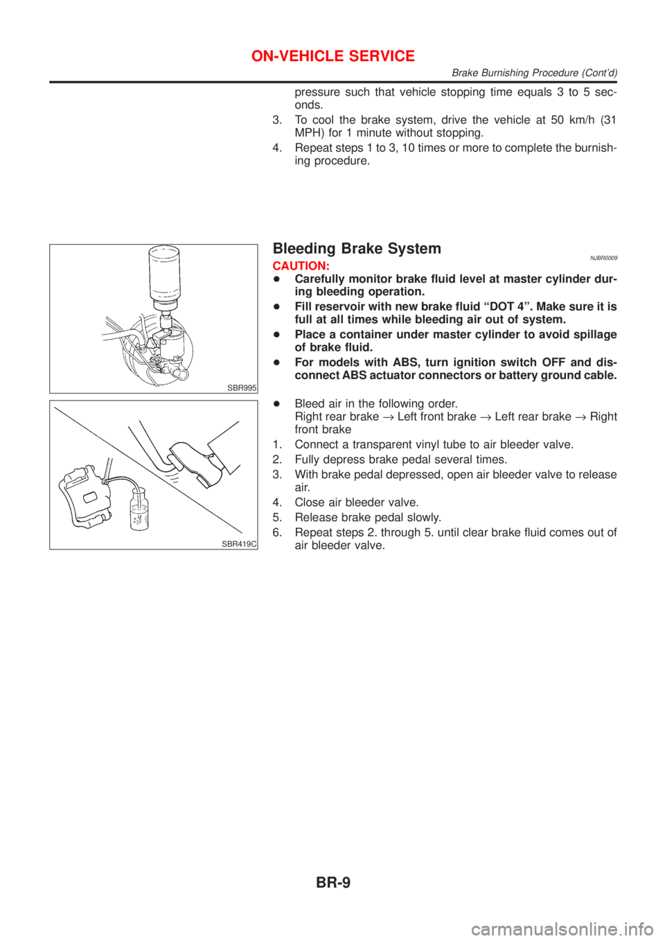
SBR995
Bleeding Brake SystemNJBR0009CAUTION:
+Carefully monitor brake fluid level at master cylinder dur-
ing bleeding operation.
+Fill reservoir with new brake fluid ªDOT 4º. Make sure it is
full at all times while bleeding air out of system.
+Place a container under master cylinder to avoid spillage
of brake fluid.
+For models with ABS, turn ignition switch OFF and dis-
connect ABS actuator connectors or battery ground cable.
SBR419C
+Bleed air in the following order.
Right rear brake®Left front brake®Left rear brake®Right
front brake
1. Connect a transparent vinyl tube to air bleeder valve.
2. Fully depress brake pedal several times.
3. With brake pedal depressed, open air bleeder valve to release
air.
4. Close air bleeder valve.
5. Release brake pedal slowly.
6. Repeat steps 2. through 5. until clear brake fluid comes out of
air bleeder valve.
ON-VEHICLE SERVICE
Brake Burnishing Procedure (Cont'd)
BR-9
Page 565 of 2898
PurposeNJBR0082The ABS consists of electronic and hydraulic components. It allows for control of braking force so that lock-
ing of the wheels can be avoided.
The ABS:
1) Ensures proper tracking performance through steering wheel operation.
2) Enables obstacles to be avoided through steering wheel operation.
3) Ensures vehicle stability by preventing flat spins.
ABS (Anti-Lock Brake System) OperationNJBR0083+When the vehicle speed is less than 10 km/h (6 MPH) this system does not work.
+The Anti-Lock Brake System (ABS) has self-test capabilities. The system turns on the ABS warning lamp
for 1 second after turning the ignition switch ON. The system performs another test the first time the vehicle
reaches 6 km/h (4 MPH). A mechanical noise may be heard as the ABS performs a self-test. This is a
normal part of the self-test feature. If a malfunction is found during this check, the ABS warning lamp will
come on.
+During ABS operation, a mechanical noise may be heard. This is a normal condition.
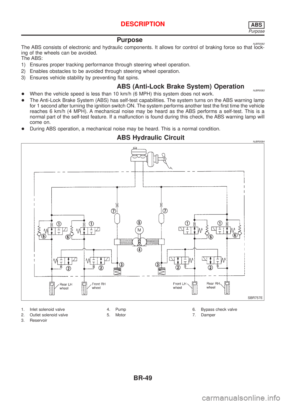
ABS Hydraulic CircuitNJBR0084
SBR757E
1. Inlet solenoid valve
2. Outlet solenoid valve
3. Reservoir4. Pump
5. Motor6. Bypass check valve
7. Damper
DESCRIPTIONABS
Purpose
BR-49
Page 579 of 2898
Self-diagnosis (Only Models with Data Link
Connector Terminal No. 9)
NJBR0091FUNCTIONNJBR0091S01+When a problem occurs in the ABS, the ABS warning lamp on
the instrument panel comes on. To start the self-diagnostic
results mode, ground the self-diagnostic (check) terminal
located on ªData link connectorº. The location of the malfunc-
tion is indicated by the ABS warning lamp flashing.
SELF-DIAGNOSIS PROCEDURENJBR0091S021. Drive vehicle over 30 km/h (19 MPH) for at least one minute.
2. Turn ignition switch ªOFFº.
SEF378Y
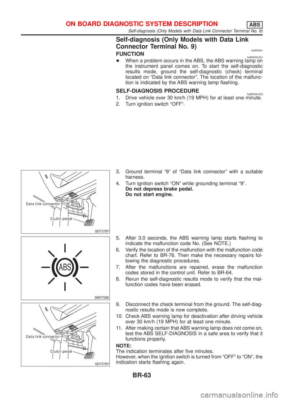
3. Ground terminal ª9º of ªData link connectorº with a suitable
harness.
4. Turn ignition switch ªONº while grounding terminal ª9º.
Do not depress brake pedal.
Do not start engine.
SBR759E
5. After 3.0 seconds, the ABS warning lamp starts flashing to
indicate the malfunction code No. (See NOTE.)
6. Verify the location of the malfunction with the malfunction code
chart. Refer to BR-76. Then make the necessary repairs fol-
lowing the diagnostic procedures.
7. After the malfunctions are repaired, erase the malfunction
codes stored in the control unit. Refer to BR-64.
8. Rerun the self-diagnostic results mode to verify that the mal-
function codes have been erased.
SEF378Y
9. Disconnect the check terminal from the ground. The self-diag-
nostic results mode is now complete.
10. Check ABS warning lamp for deactivation after driving vehicle
over 30 km/h (19 MPH) for at least one minute.
11. After making certain that ABS warning lamp does not come on,
test the ABS SELF-DIAGNOSIS in a safe area to verify that it
functions properly.
NOTE:
The indication terminates after five minutes.
However, when the ignition switch is turned from ªOFFº to ªONº, the
indication starts flashing again.
ON BOARD DIAGNOSTIC SYSTEM DESCRIPTIONABS
Self-diagnosis (Only Models with Data Link Connector Terminal No. 9)
BR-63
Page 581 of 2898
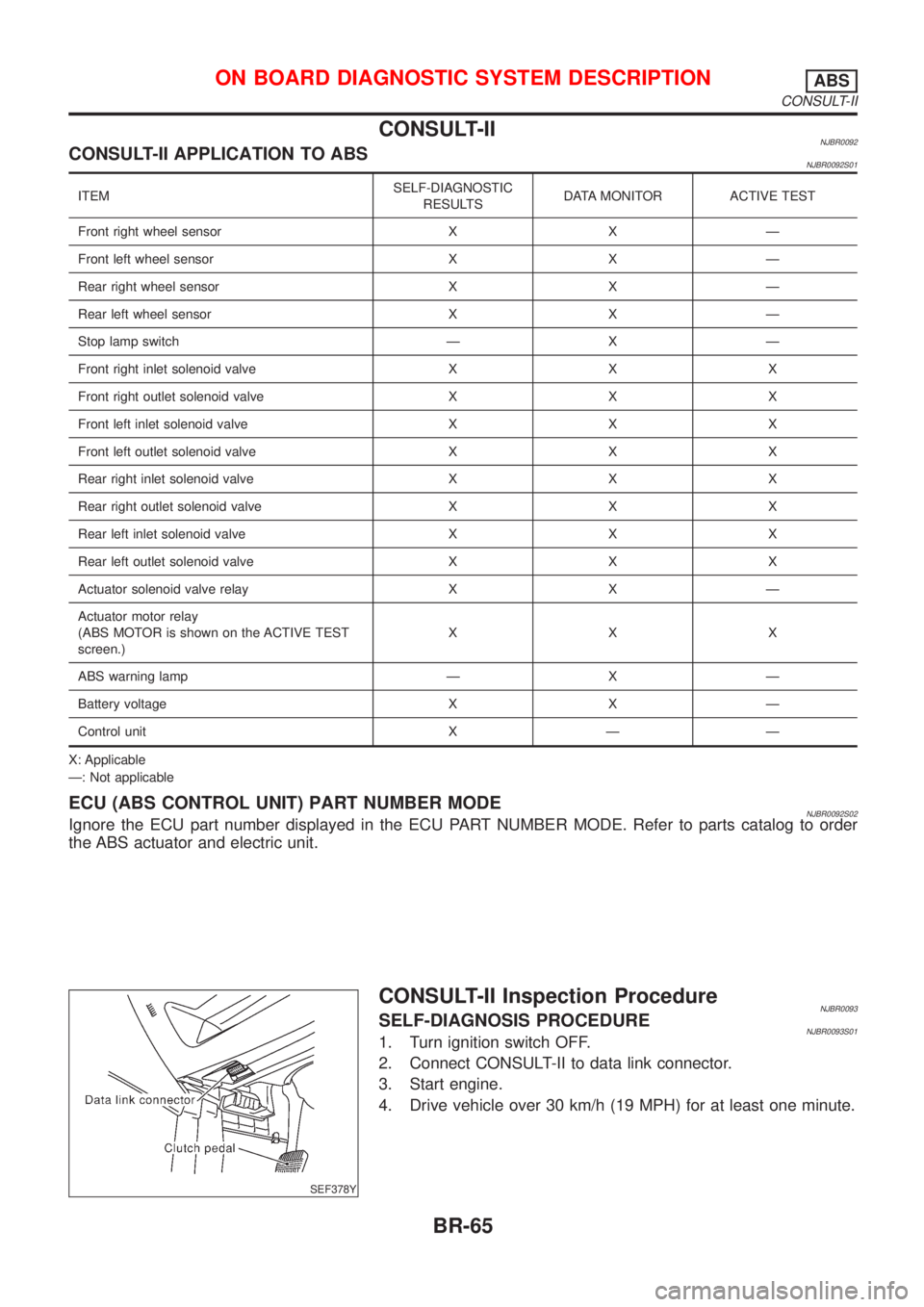
CONSULT-IINJBR0092CONSULT-II APPLICATION TO ABSNJBR0092S01
ITEMSELF-DIAGNOSTIC
RESULTSDATA MONITOR ACTIVE TEST
Front right wheel sensor X X Ð
Front left wheel sensor X X Ð
Rear right wheel sensor X X Ð
Rear left wheel sensor X X Ð
Stop lamp switch Ð X Ð
Front right inlet solenoid valve X X X
Front right outlet solenoid valve X X X
Front left inlet solenoid valve X X X
Front left outlet solenoid valve X X X
Rear right inlet solenoid valve X X X
Rear right outlet solenoid valve X X X
Rear left inlet solenoid valve X X X
Rear left outlet solenoid valve X X X
Actuator solenoid valve relay X X Ð
Actuator motor relay
(ABS MOTOR is shown on the ACTIVE TEST
screen.)XXX
ABS warning lamp Ð X Ð
Battery voltage X X Ð
Control unit X Ð Ð
X: Applicable
Ð: Not applicable
ECU (ABS CONTROL UNIT) PART NUMBER MODENJBR0092S02Ignore the ECU part number displayed in the ECU PART NUMBER MODE. Refer to parts catalog to order
the ABS actuator and electric unit.
SEF378Y
CONSULT-II Inspection ProcedureNJBR0093SELF-DIAGNOSIS PROCEDURENJBR0093S011. Turn ignition switch OFF.
2. Connect CONSULT-II to data link connector.
3. Start engine.
4. Drive vehicle over 30 km/h (19 MPH) for at least one minute.
ON BOARD DIAGNOSTIC SYSTEM DESCRIPTIONABS
CONSULT-II
BR-65
Page 582 of 2898
PBR455D
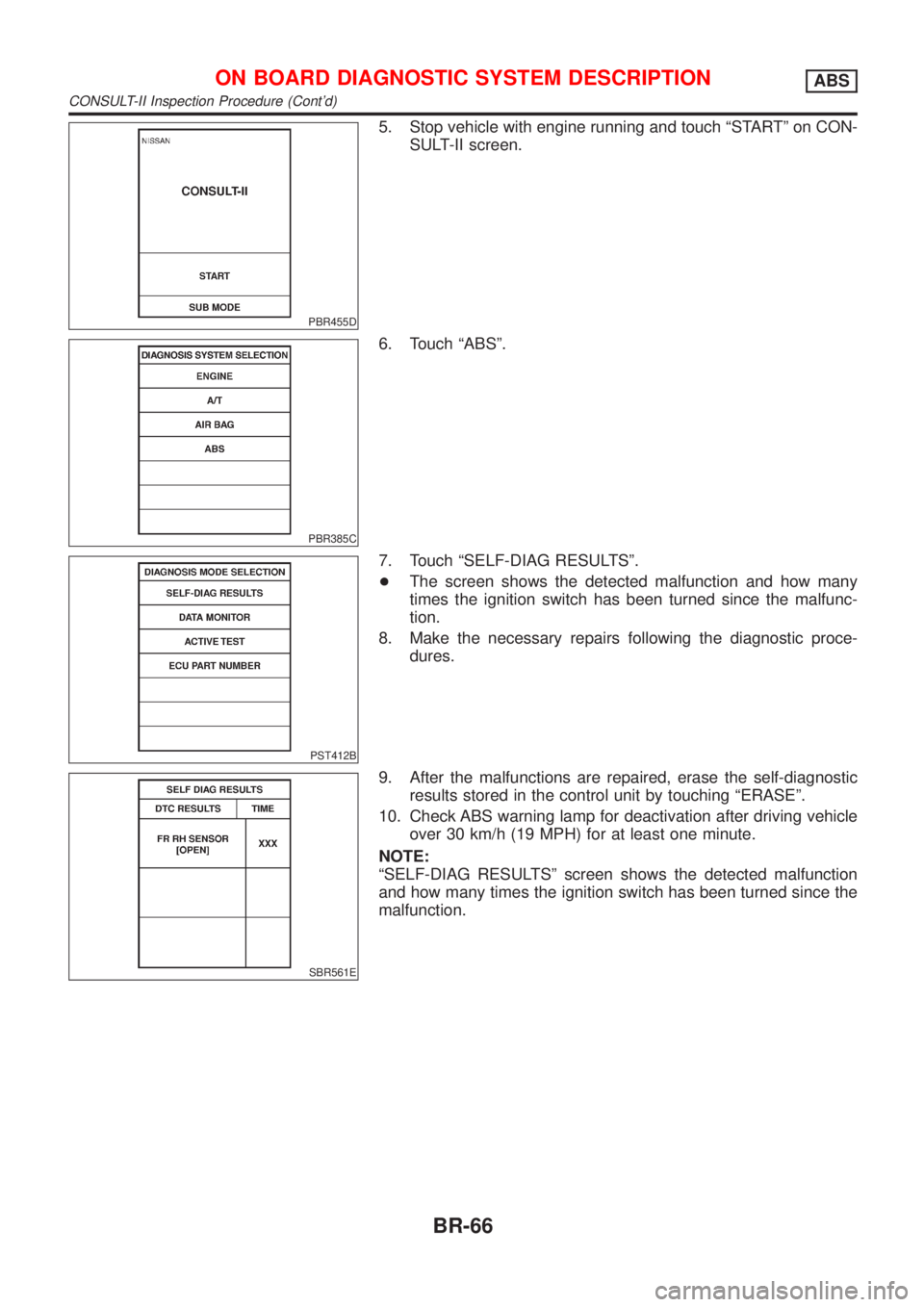
5. Stop vehicle with engine running and touch ªSTARTº on CON-
SULT-II screen.
PBR385C
6. Touch ªABSº.
PST412B
7. Touch ªSELF-DIAG RESULTSº.
+The screen shows the detected malfunction and how many
times the ignition switch has been turned since the malfunc-
tion.
8. Make the necessary repairs following the diagnostic proce-
dures.
SBR561E
9. After the malfunctions are repaired, erase the self-diagnostic
results stored in the control unit by touching ªERASEº.
10. Check ABS warning lamp for deactivation after driving vehicle
over 30 km/h (19 MPH) for at least one minute.
NOTE:
ªSELF-DIAG RESULTSº screen shows the detected malfunction
and how many times the ignition switch has been turned since the
malfunction.
ON BOARD DIAGNOSTIC SYSTEM DESCRIPTIONABS
CONSULT-II Inspection Procedure (Cont'd)
BR-66
Page 584 of 2898
![NISSAN ALMERA 2001 Service Manual Diagnostic item Diagnostic item is detected when ...Reference
Page
RR RH OUT ABS SOL
[SHORT]+Circuit for rear right outlet solenoid valve is shorted.
(An abnormally high output voltage is entered.)BR- NISSAN ALMERA 2001 Service Manual Diagnostic item Diagnostic item is detected when ...Reference
Page
RR RH OUT ABS SOL
[SHORT]+Circuit for rear right outlet solenoid valve is shorted.
(An abnormally high output voltage is entered.)BR-](/manual-img/5/57348/w960_57348-583.png)
Diagnostic item Diagnostic item is detected when ...Reference
Page
RR RH OUT ABS SOL
[SHORT]+Circuit for rear right outlet solenoid valve is shorted.
(An abnormally high output voltage is entered.)BR-81
RR LH OUT ABS SOL
[SHORT]+Circuit for rear left outlet solenoid valve is shorted.
(An abnormally high output voltage is entered.)BR-81
ABS ACTUATOR RELAY
[ABNORMAL]+Actuator solenoid valve relay is ON, even control unit sends off signal.
+Actuator solenoid valve relay is OFF, even control unit sends on signal.BR-81
ABS MOTOR RELAY
[ABNORMAL]+Circuit for actuator motor is open or shorted.
+Actuator motor relay is stuck.BR-84
BATTERY VOLT
[ABNORMAL]+Power source voltage supplied to ABS control unit is abnormally low. BR-86
CONTROL UNIT+Function of calculation in ABS control unit has failed. BR-88
*1: Be sure to confirm the ABS warning lamp illuminates when the ignition switch is turned ON after repairing the shorted sensor circuit,
but the lamp goes out when driving the vehicle over 30 km/h (19 MPH) for one minute in accordance with SELF-DIAGNOSIS
PROCEDURE.
PBR455D
DATA MONITOR PROCEDURENJBR0093S031. Turn ignition switch OFF.
2. Connect CONSULT-II to data link connector.
3. Turn ignition switch ON.
4. Touch ªSTARTº on CONSULT-II screen.
PBR385C
5. Touch ªABSº.
PST412B
6. Touch ªDATA MONITORº.
7. Touch ªSETTINGº on ªSELECT MONITOR ITEMº screen.
8. Touch ªLONG TIMEº on ªSET RECORDING CONDº screen.
9. Touch ªSTARTº on ªSELECT MONITOR ITEMº.
ON BOARD DIAGNOSTIC SYSTEM DESCRIPTIONABS
CONSULT-II Inspection Procedure (Cont'd)
BR-68
Page 585 of 2898
PBR455D
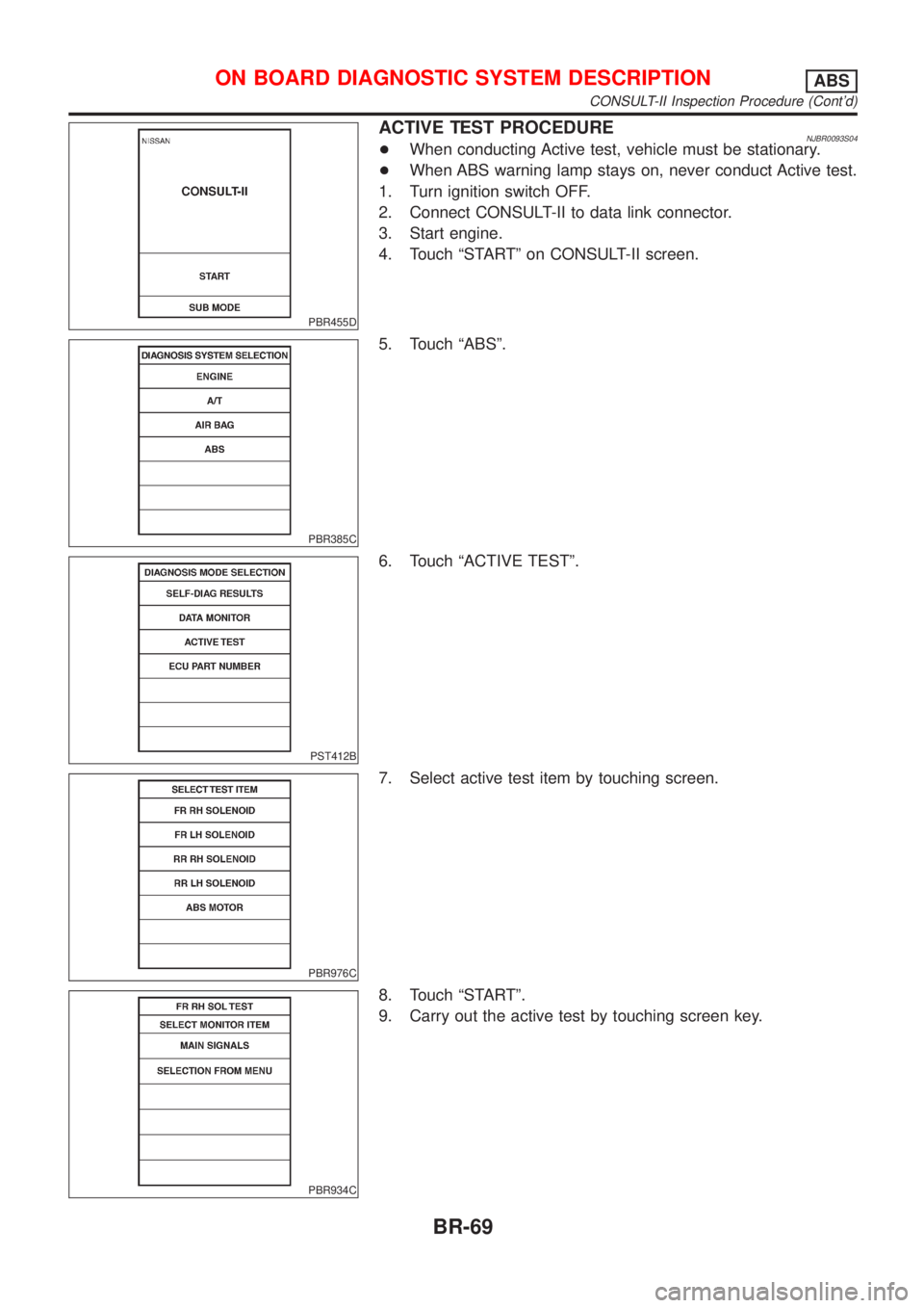
ACTIVE TEST PROCEDURENJBR0093S04+When conducting Active test, vehicle must be stationary.
+When ABS warning lamp stays on, never conduct Active test.
1. Turn ignition switch OFF.
2. Connect CONSULT-II to data link connector.
3. Start engine.
4. Touch ªSTARTº on CONSULT-II screen.
PBR385C
5. Touch ªABSº.
PST412B
6. Touch ªACTIVE TESTº.
PBR976C
7. Select active test item by touching screen.
PBR934C
8. Touch ªSTARTº.
9. Carry out the active test by touching screen key.
ON BOARD DIAGNOSTIC SYSTEM DESCRIPTIONABS
CONSULT-II Inspection Procedure (Cont'd)
BR-69