Page 1048 of 2898
SEF598K
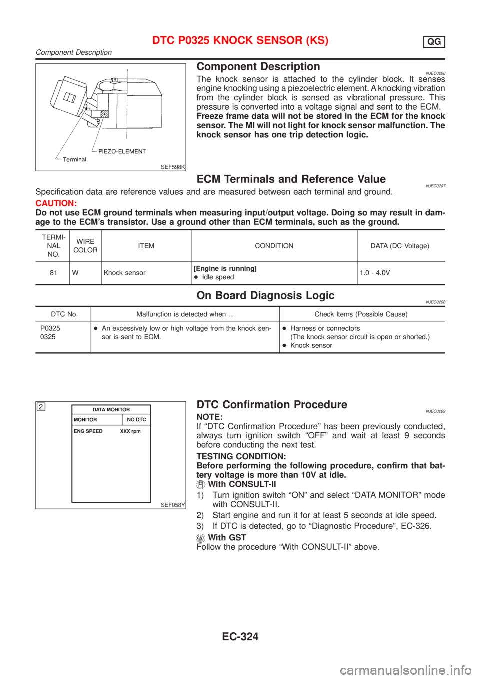
Component DescriptionNJEC0206The knock sensor is attached to the cylinder block. It senses
engine knocking using a piezoelectric element. A knocking vibration
from the cylinder block is sensed as vibrational pressure. This
pressure is converted into a voltage signal and sent to the ECM.
Freeze frame data will not be stored in the ECM for the knock
sensor. The MI will not light for knock sensor malfunction. The
knock sensor has one trip detection logic.
ECM Terminals and Reference ValueNJEC0207Specification data are reference values and are measured between each terminal and ground.
CAUTION:
Do not use ECM ground terminals when measuring input/output voltage. Doing so may result in dam-
age to the ECM's transistor. Use a ground other than ECM terminals, such as the ground.
TERMI-
NAL
NO.WIRE
COLORITEM CONDITION DATA (DC Voltage)
81 W Knock sensor[Engine is running]
+Idle speed1.0 - 4.0V
On Board Diagnosis LogicNJEC0208
DTC No. Malfunction is detected when ... Check Items (Possible Cause)
P0325
0325+An excessively low or high voltage from the knock sen-
sor is sent to ECM.+Harness or connectors
(The knock sensor circuit is open or shorted.)
+Knock sensor
SEF058Y
DTC Confirmation ProcedureNJEC0209NOTE:
If ªDTC Confirmation Procedureº has been previously conducted,
always turn ignition switch ªOFFº and wait at least 9 seconds
before conducting the next test.
TESTING CONDITION:
Before performing the following procedure, confirm that bat-
tery voltage is more than 10V at idle.
With CONSULT-II
1) Turn ignition switch ªONº and select ªDATA MONITORº mode
with CONSULT-II.
2) Start engine and run it for at least 5 seconds at idle speed.
3) If DTC is detected, go to ªDiagnostic Procedureº, EC-326.
With GST
Follow the procedure ªWith CONSULT-IIº above.
DTC P0325 KNOCK SENSOR (KS)QG
Component Description
EC-324
Page 1050 of 2898
Diagnostic ProcedureNJEC0211
1 RETIGHTEN GROUND SCREWS
Loosen and retighten engine ground screws.
JEF104Y
©GO TO 2.
2 CHECK INPUT SIGNAL CIRCUIT-1
1. Turn ignition switch ªOFFº.
2. Disconnect ECM harness connector and knock sensor harness connector.
JEF110Y
3. Check harness continuity between knock sensor signal terminal 1 and ECM terminal 81.
Refer to wiring diagram.
Continuity should exist.
4. Also check harness for short to ground and short to power.
OK or NG
OK©GO TO 4.
NG©GO TO 3.
3 DETECT MALFUNCTIONING PART
Check the harness for open or short between knock sensor and ECM.
©Repair open circuit or short to ground or short to power in harness or connectors.
4 CHECK KNOCK SENSOR
Refer to ªComponent Inspectionº, EC-327.
OK or NG
OK©GO TO 5.
NG©Replace knock sensor.
DTC P0325 KNOCK SENSOR (KS)QG
Diagnostic Procedure
EC-326
Page 1053 of 2898
On Board Diagnosis LogicNJEC0553
DTC No. Malfunction is detected when ... Check Items (Possible Cause)
P0335
0802+The 10É signal is not entered to ECM for the first few
seconds during engine cranking.
+The 10É signal is not entered to ECM during engine run-
ning.
+The 10É signal is not in the normal pattern at each
engine revolution.+Harness or connectors
(The crankshaft position sensor (POS) circuit is
open or shorted.)
+Crankshaft position sensor (POS)
+Starter motor (Refer to EL section.)
+Starting system circuit (Refer to EL section.)
+Dead (Weak) battery
SEF058Y
DTC Confirmation ProcedureNJEC0554NOTE:
If ªDTC Confirmation Procedureº has been previously conducted,
always turn ignition switch ªOFFº and wait at least 9 seconds
before conducting the next test.
With CONSULT-II
1) Turn ignition switch ªONº and select ªDATA MONITORº mode
with CONSULT-II.
2) Start engine and run it for at least 2 seconds at idle speed.
3) If 1st trip DTC is detected, go to ªDiagnostic Procedureº,
EC-332.
With GST
Follow the procedure ªWith CONSULT-IIº above.
DTC P0335 CRANKSHAFT POSITION SENSOR (POS)QG
On Board Diagnosis Logic
EC-329
Page 1060 of 2898
On Board Diagnosis LogicNJEC0222
DTC No. Malfunction is detected when ... Check Items (Possible Cause)
P0340
0340+The cylinder No. signal is not entered to ECM for the first
few seconds during engine cranking.
+The cylinder No. signal is not entered to ECM during
engine running.
+The cylinder No. signal is not in the normal pattern dur-
ing engine running.+Harness or connectors
(The camshaft position sensor (PHASE) circuit is
open or shorted.)
+Camshaft position sensor (PHASE)
+Starter motor (Refer to EL section.)
+Starting system circuit (Refer to EL section.)
DTC Confirmation ProcedureNJEC0223NOTE:
If ªDTC Confirmation Procedureº has been previously conducted,
always turn ignition switch ªOFFº and wait at least 9 seconds
before conducting the next test.
TESTING CONDITION:
Before performing the following procedure, confirm that bat-
tery voltage is more than 10.5V.
SEF013Y
With CONSULT-II
1) Turn ignition switch ªONº.
2) Select ªDATA MONITORº mode with CONSULT-II.
3) Crank engine for at least 2 seconds.
4) If 1st trip DTC is detected, go to ªDiagnostic Procedureº,
EC-339.
With GST
Follow the procedure ªWith CONSULT-IIº above.
DTC P0340 CAMSHAFT POSITION SENSOR (CMPS) (PHASE)QG
On Board Diagnosis Logic
EC-336
Page 1064 of 2898
3 CHECK POWER SUPPLY
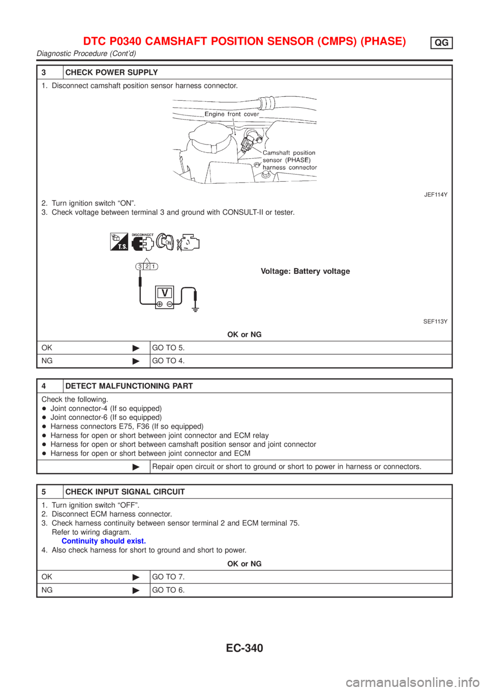
1. Disconnect camshaft position sensor harness connector.
JEF114Y
2. Turn ignition switch ªONº.
3. Check voltage between terminal 3 and ground with CONSULT-II or tester.
SEF113Y
OK or NG
OK©GO TO 5.
NG©GO TO 4.
4 DETECT MALFUNCTIONING PART
Check the following.
+Joint connector-4 (If so equipped)
+Joint connector-6 (If so equipped)
+Harness connectors E75, F36 (If so equipped)
+Harness for open or short between joint connector and ECM relay
+Harness for open or short between camshaft position sensor and joint connector
+Harness for open or short between joint connector and ECM
©Repair open circuit or short to ground or short to power in harness or connectors.
5 CHECK INPUT SIGNAL CIRCUIT
1. Turn ignition switch ªOFFº.
2. Disconnect ECM harness connector.
3. Check harness continuity between sensor terminal 2 and ECM terminal 75.
Refer to wiring diagram.
Continuity should exist.
4. Also check harness for short to ground and short to power.
OK or NG
OK©GO TO 7.
NG©GO TO 6.
DTC P0340 CAMSHAFT POSITION SENSOR (CMPS) (PHASE)QG
Diagnostic Procedure (Cont'd)
EC-340
Page 1068 of 2898
SEF552W
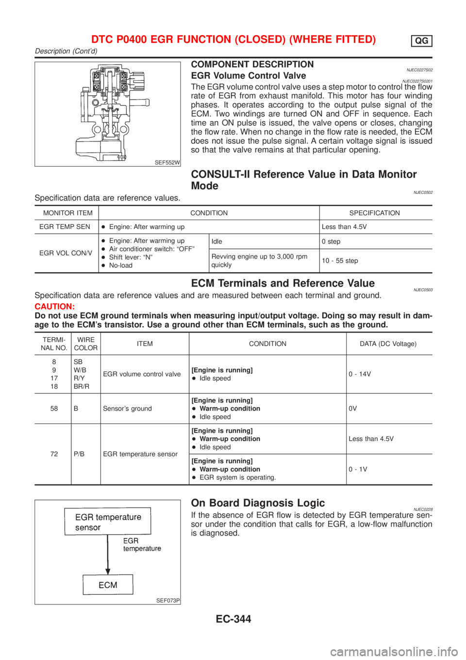
COMPONENT DESCRIPTIONNJEC0227S02EGR Volume Control ValveNJEC0227S0201The EGR volume control valve uses a step motor to control the flow
rate of EGR from exhaust manifold. This motor has four winding
phases. It operates according to the output pulse signal of the
ECM. Two windings are turned ON and OFF in sequence. Each
time an ON pulse is issued, the valve opens or closes, changing
the flow rate. When no change in the flow rate is needed, the ECM
does not issue the pulse signal. A certain voltage signal is issued
so that the valve remains at that particular opening.
CONSULT-II Reference Value in Data Monitor
Mode
NJEC0502Specification data are reference values.
MONITOR ITEM CONDITION SPECIFICATION
EGR TEMP SEN+Engine: After warming up Less than 4.5V
EGR VOL CON/V+Engine: After warming up
+Air conditioner switch: ªOFFº
+Shift lever: ªNº
+No-loadIdle 0 step
Revving engine up to 3,000 rpm
quickly10 - 55 step
ECM Terminals and Reference ValueNJEC0503Specification data are reference values and are measured between each terminal and ground.
CAUTION:
Do not use ECM ground terminals when measuring input/output voltage. Doing so may result in dam-
age to the ECM's transistor. Use a ground other than ECM terminals, such as the ground.
TERMI-
NAL NO.WIRE
COLORITEM CONDITION DATA (DC Voltage)
8
9
17
18SB
W/B
R/Y
BR/REGR volume control valve[Engine is running]
+Idle speed0 - 14V
58 B Sensor's ground[Engine is running]
+Warm-up condition
+Idle speed0V
72 P/B EGR temperature sensor[Engine is running]
+Warm-up condition
+Idle speedLess than 4.5V
[Engine is running]
+Warm-up condition
+EGR system is operating.0-1V
SEF073P
On Board Diagnosis LogicNJEC0228If the absence of EGR flow is detected by EGR temperature sen-
sor under the condition that calls for EGR, a low-flow malfunction
is diagnosed.
DTC P0400 EGR FUNCTION (CLOSED) (WHERE FITTED)QG
Description (Cont'd)
EC-344
Page 1074 of 2898
4 CHECK OUTPUT SIGNAL CIRCUIT
1. Turn ignition switch ªOFFº.
2. Disconnect ECM harness connector.
3. Check harness continuity between
ECM terminal 8 and terminal 1,
ECM terminal 9 and terminal 4,
ECM terminal 17 and terminal 3,
ECM terminal 18 and terminal 6.
Refer to wiring diagram.
Continuity should exist.
If OK, check harness for short to ground and short to power.
OK or NG
OK©GO TO 5.
NG©Repair open circuit, short to ground or short to power in harness connectors.
5 CHECK EGR PASSAGE
Check EGR passage for clogging and cracks.
OK or NG
OK©GO TO 6.
NG©Repair or replace EGR passage.
6 CHECK EGR TEMPERATURE SENSOR
Refer to ªCOMPONENT INSPECTIONº, EC-424.
OK or NG
OK©GO TO 7.
NG©Replace EGR temperature sensor.
7 CHECK EGR VOLUME CONTROL VALVE
Refer to ªCOMPONENT INSPECTIONº, EC-351.
OK or NG
OK©GO TO 8.
NG©Replace EGR volume control valve.
8 CHECK INTERMITTENT INCIDENT
Perform ªTROUBLE DIAGNOSIS FOR INTERMITTENT INCIDENTº, EC-177.
©INSPECTION END
DTC P0400 EGR FUNCTION (CLOSED) (WHERE FITTED)QG
Diagnostic Procedure (Cont'd)
EC-350
Page 1077 of 2898
SEF552W
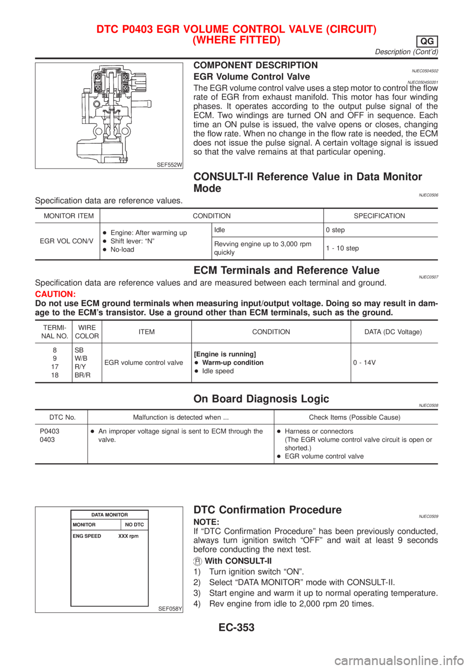
COMPONENT DESCRIPTIONNJEC0504S02EGR Volume Control ValveNJEC0504S0201The EGR volume control valve uses a step motor to control the flow
rate of EGR from exhaust manifold. This motor has four winding
phases. It operates according to the output pulse signal of the
ECM. Two windings are turned ON and OFF in sequence. Each
time an ON pulse is issued, the valve opens or closes, changing
the flow rate. When no change in the flow rate is needed, the ECM
does not issue the pulse signal. A certain voltage signal is issued
so that the valve remains at that particular opening.
CONSULT-II Reference Value in Data Monitor
Mode
NJEC0506Specification data are reference values.
MONITOR ITEM CONDITION SPECIFICATION
EGR VOL CON/V+Engine: After warming up
+Shift lever: ªNº
+No-loadIdle 0 step
Revving engine up to 3,000 rpm
quickly1 - 10 step
ECM Terminals and Reference ValueNJEC0507Specification data are reference values and are measured between each terminal and ground.
CAUTION:
Do not use ECM ground terminals when measuring input/output voltage. Doing so may result in dam-
age to the ECM's transistor. Use a ground other than ECM terminals, such as the ground.
TERMI-
NAL NO.WIRE
COLORITEM CONDITION DATA (DC Voltage)
8
9
17
18SB
W/B
R/Y
BR/REGR volume control valve[Engine is running]
+Warm-up condition
+Idle speed0 - 14V
On Board Diagnosis LogicNJEC0508
DTC No. Malfunction is detected when ... Check Items (Possible Cause)
P0403
0403+An improper voltage signal is sent to ECM through the
valve.+Harness or connectors
(The EGR volume control valve circuit is open or
shorted.)
+EGR volume control valve
SEF058Y
DTC Confirmation ProcedureNJEC0509NOTE:
If ªDTC Confirmation Procedureº has been previously conducted,
always turn ignition switch ªOFFº and wait at least 9 seconds
before conducting the next test.
With CONSULT-II
1) Turn ignition switch ªONº.
2) Select ªDATA MONITORº mode with CONSULT-II.
3) Start engine and warm it up to normal operating temperature.
4) Rev engine from idle to 2,000 rpm 20 times.
DTC P0403 EGR VOLUME CONTROL VALVE (CIRCUIT)
(WHERE FITTED)
QG
Description (Cont'd)
EC-353