2001 NISSAN ALMERA N16 rear lam
[x] Cancel search: rear lamPage 1937 of 2493
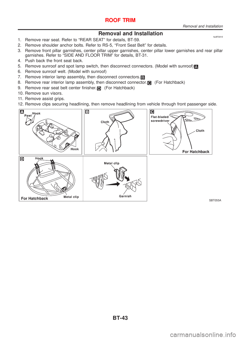
Removal and InstallationNJBT00151. Remove rear seat. Refer to ªREAR SEATº for details, BT-59.
2. Remove shoulder anchor bolts. Refer to RS-5, ªFront Seat Beltº for details.
3. Remove front pillar garnishes, center pillar upper garnishes, center pillar lower garnishes and rear pillar
garnishes. Refer to ªSIDE AND FLOOR TRIMº for details, BT-31.
4. Push back the front seat back.
5. Remove sunroof and spot lamp switch, then disconnect connectors. (Model with sunroof)
6. Remove sunroof welt. (Model with sunroof)
7. Remove interior lamp assembly, then disconnect connectors.
8. Remove rear interior lamp assembly, then disconnect connector.(For Hatchback)
9. Remove rear seat belt center finisher.
(For Hatchback)
10. Remove sun visors.
11. Remove assist grips.
12. Remove clips securing headlining, then remove headlining from vehicle through front passenger side.
SBT055A
ROOF TRIM
Removal and Installation
BT-43
Page 1991 of 2493
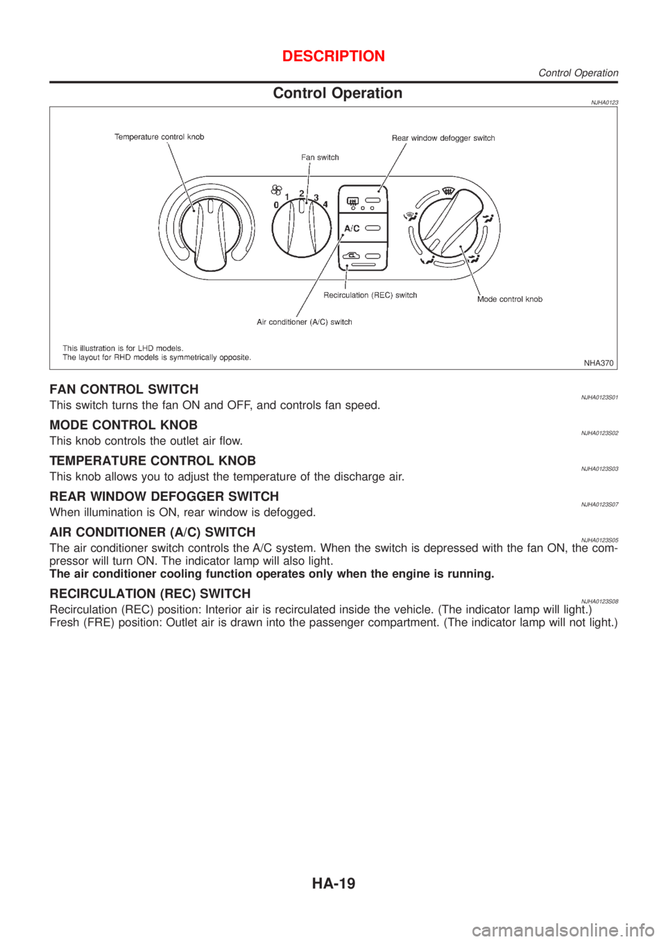
Control OperationNJHA0123
NHA370
FAN CONTROL SWITCHNJHA0123S01This switch turns the fan ON and OFF, and controls fan speed.
MODE CONTROL KNOBNJHA0123S02This knob controls the outlet air flow.
TEMPERATURE CONTROL KNOBNJHA0123S03This knob allows you to adjust the temperature of the discharge air.
REAR WINDOW DEFOGGER SWITCHNJHA0123S07When illumination is ON, rear window is defogged.
AIR CONDITIONER (A/C) SWITCHNJHA0123S05The air conditioner switch controls the A/C system. When the switch is depressed with the fan ON, the com-
pressor will turn ON. The indicator lamp will also light.
The air conditioner cooling function operates only when the engine is running.
RECIRCULATION (REC) SWITCHNJHA0123S08Recirculation (REC) position: Interior air is recirculated inside the vehicle. (The indicator lamp will light.)
Fresh (FRE) position: Outlet air is drawn into the passenger compartment. (The indicator lamp will not light.)
DESCRIPTION
Control Operation
HA-19
Page 2113 of 2493
ELECTRICAL SYSTEM
SECTION
EL
CONTENTS
PRECAUTIONS...............................................................4
Supplemental Restraint System (SRS)²AIR
BAG²and²SEAT BELT PRE-TENSIONER²...............4
Wiring Diagrams and Trouble Diagnosis .....................4
HARNESS CONNECTOR................................................5
Description ...................................................................5
STANDARDIZED RELAY................................................7
Description ...................................................................7
POWER SUPPLY ROUTING...........................................9
Schematic ..................................................................10
Wiring Diagram - POWER - ......................................12
Inspection...................................................................22
GROUND........................................................................23
Ground Distribution ....................................................23
COMBINATION SWITCH..............................................37
Check .........................................................................37
Replacement ..............................................................38
STEERING SWITCH......................................................39
Check .........................................................................39
HEADLAMP...................................................................40
Wiring Diagram - H/LAMP -.......................................40
Trouble Diagnoses.....................................................41
Bulb Replacement .....................................................42
Aiming Adjustment .....................................................42
HEADLAMP - DAYTIME LIGHT SYSTEM -.................44
System Description ....................................................44
Schematic ..................................................................45
Wiring Diagram - DTRL - ...........................................46
Trouble Diagnoses.....................................................49
Bulb Replacement .....................................................49
Aiming Adjustment .....................................................50
HEADLAMP - HEADLAMP AIMING CONTROL -........51
Wiring Diagram - H/AIM - ..........................................51
PARKING, LICENSE AND TAIL LAMPS.....................53
Wiring Diagram - TAIL/L - ..........................................53
STOP LAMP..................................................................56
Wiring Diagram - STOP/L - .......................................56
BACK-UP LAMP............................................................58
Wiring Diagram - BACK/L - .......................................58FRONT FOG LAMP.......................................................60
Wiring Diagram - F/FOG - .........................................60
Bulb Replacement .....................................................61
Aiming Adjustment .....................................................62
REAR FOG LAMP.........................................................63
Wiring Diagram - R/FOG -.........................................63
TURN SIGNAL AND HAZARD WARNING LAMPS.....65
System Description ....................................................65
Schematic ..................................................................66
Wiring Diagram - TURN - ..........................................67
Trouble Diagnoses.....................................................70
ILLUMINATION..............................................................71
Schematic ..................................................................71
Wiring Diagram - ILL - ...............................................72
INTERIOR ROOM LAMP...............................................76
System Description/ With Interior Room Lamp
Timer ..........................................................................76
Wiring Diagram - ROOM/L -/ With Interior Room
Lamp Timer ................................................................78
Trouble Diagnoses/ With Interior Room Lamp
Timer ..........................................................................80
Wiring Diagram - ROOM/L -/ Without Timer .............86
SPOT AND TRUNK ROOM LAMPS.............................87
Wiring Diagram - INT/L - ...........................................87
METERS AND GAUGES...............................................89
Component Parts and Harness Connector
Location .....................................................................89
System Description ....................................................89
Combination Meter ....................................................91
Schematic ..................................................................92
Construction ...............................................................93
Wiring Diagram - METER - .......................................94
Combination Meter Self-Diagnosis ............................96
Trouble Diagnoses.....................................................99
Electrical Components Inspection ...........................106
WARNING LAMPS......................................................107
Schematic ................................................................107
Wiring Diagram - WARN - .......................................108
Electrical Components Inspection ........................... 112
Page 2114 of 2493
WARNING CHIME....................................................... 113
Component Parts and Harness Connector
Location ................................................................... 113
System Description .................................................. 113
Wiring Diagram - CHIME - ...................................... 115
Trouble Diagnoses................................................... 117
FRONT WIPER AND WASHER..................................123
System Description ..................................................123
Wiring Diagram - WIPER - ......................................125
Removal and Installation .........................................127
Washer Nozzle Adjustment .....................................128
Washer Tube Layout ...............................................128
REAR WIPER AND WASHER....................................129
Wiring Diagram - WIP/R -........................................129
Removal and Installation .........................................131
Washer Nozzle Adjustment .....................................131
Washer Tube Layout ...............................................132
HEADLAMP WASHER................................................133
Wiring Diagram - HLC - ...........................................133
Washer Tube Layout ...............................................134
HORN...........................................................................135
Wiring Diagram - HORN - .......................................135
CIGARETTE LIGHTER................................................136
Wiring Diagram - CIGAR -.......................................136
CLOCK.........................................................................137
Wiring Diagram - CLOCK -......................................137
REAR WINDOW DEFOGGER.....................................138
System Description ..................................................138
Schematic ................................................................139
Wiring Diagram - DEF - ...........................................140
Trouble Diagnoses...................................................143
Electrical Components Inspection ...........................146
Filament Check ........................................................147
Filament Repair .......................................................148
AUDIO..........................................................................149
System Description ..................................................149
Schematic ................................................................151
Wiring Diagram - AUDIO - .......................................152
Trouble Diagnoses...................................................160
Inspection.................................................................161
AUDIO ANTENNA.......................................................162
Location of Antenna .................................................162
Antenna Rod Replacement .....................................162
HEATED SEAT............................................................163
Wiring Diagram - H/SEAT - .....................................163
POWER SUNROOF.....................................................165
Wiring Diagram - SROOF - .....................................165
Trouble Diagnoses...................................................166
DOOR MIRROR...........................................................167
Wiring Diagram - MIRROR - ...................................167
POWER WINDOW.......................................................169
System Description ..................................................169Schematic ................................................................171
Wiring Diagram - WINDOW - ..................................172
Trouble Diagnoses...................................................176
POWER DOOR LOCK.................................................177
System Description ..................................................177
Schematic ................................................................178
Wiring Diagram - D/LOCK -.....................................180
Trouble Diagnoses...................................................187
POWER DOOR LOCK - SUPER LOCK -...................196
System Description ..................................................196
Schematic ................................................................198
Wiring Diagram - S/LOCK - .....................................200
Trouble Diagnoses...................................................207
MULTI-REMOTE CONTROL SYSTEM.......................220
System Description ..................................................220
Wiring Diagram - MULTI - .......................................221
Trouble Diagnoses...................................................223
ID Code Entry Procedure ........................................227
Remote Controller Battery Replacement.................228
TIME CONTROL UNIT................................................229
Description ...............................................................229
Trouble Diagnoses...................................................230
Schematic ................................................................232
NATS (NISSAN ANTI-THEFT SYSTEM).....................234
Component Parts and Harness Connetor
Location ...................................................................234
System Description ..................................................234
System Composition ................................................236
Wiring Diagram - NATS -.........................................237
CONSULT-II .............................................................238
Trouble Diagnoses...................................................241
How to Replace NATS IMMU ..................................258
NAVIGATION SYSTEM...............................................259
Precautions ..............................................................259
Component Parts Location ......................................260
System Description ..................................................261
Schematic ................................................................269
Wiring Diagram - NAVI - ..........................................270
Self-diagnosis Mode ................................................278
Confirmation/Adjustment Mode ...............................281
Control Panel Mode .................................................293
Guide Volume Setting ..............................................300
Anti-theft System .....................................................301
CONSULT-II .............................................................302
Trouble Diagnoses...................................................303
This Condition Is Not Abnormal...............................309
Program Loading .....................................................318
ELECTRICAL UNITS LOCATION...............................319
Engine Compartment ...............................................319
Passenger Compartment/LHD Models ....................320
Passenger Compartment/RHD Models ...................322
CONTENTS(Cont'd)
EL-2
Page 2115 of 2493
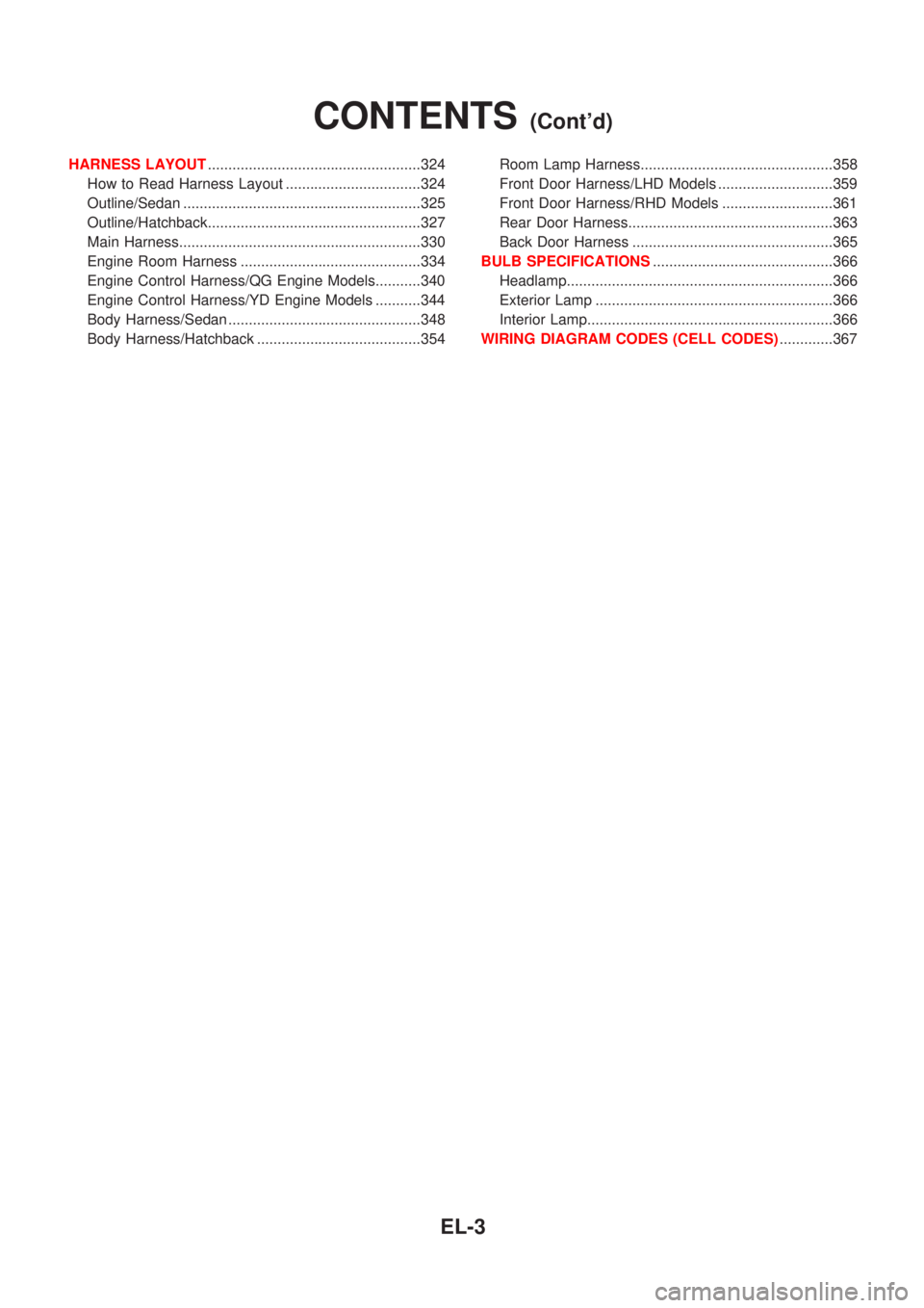
HARNESS LAYOUT....................................................324
How to Read Harness Layout .................................324
Outline/Sedan ..........................................................325
Outline/Hatchback....................................................327
Main Harness...........................................................330
Engine Room Harness ............................................334
Engine Control Harness/QG Engine Models...........340
Engine Control Harness/YD Engine Models ...........344
Body Harness/Sedan ...............................................348
Body Harness/Hatchback ........................................354Room Lamp Harness...............................................358
Front Door Harness/LHD Models ............................359
Front Door Harness/RHD Models ...........................361
Rear Door Harness..................................................363
Back Door Harness .................................................365
BULB SPECIFICATIONS............................................366
Headlamp.................................................................366
Exterior Lamp ..........................................................366
Interior Lamp............................................................366
WIRING DIAGRAM CODES (CELL CODES).............367
CONTENTS(Cont'd)
EL-3
Page 2148 of 2493
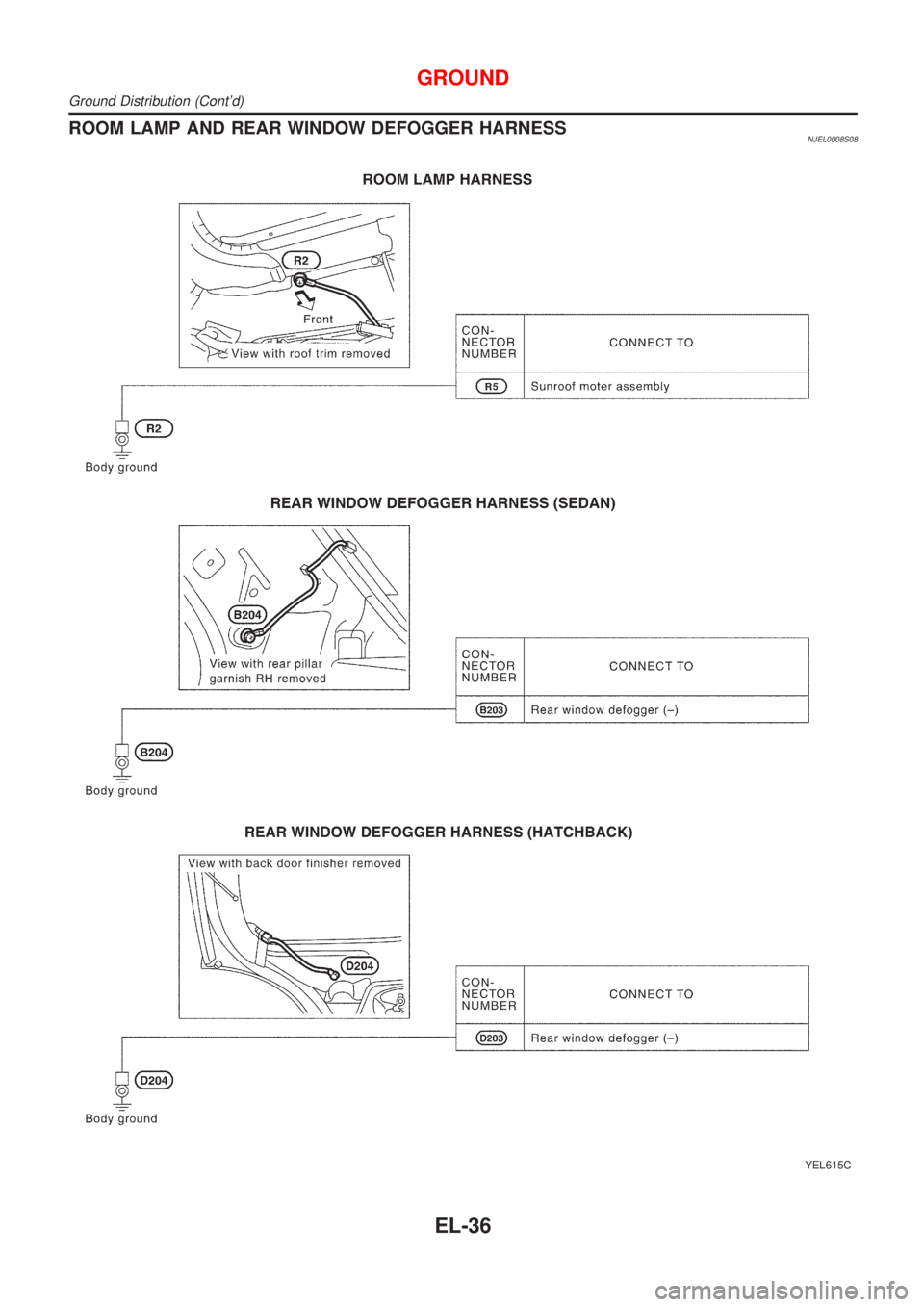
ROOM LAMP AND REAR WINDOW DEFOGGER HARNESSNJEL0008S08
YEL615C
GROUND
Ground Distribution (Cont'd)
EL-36
Page 2175 of 2493
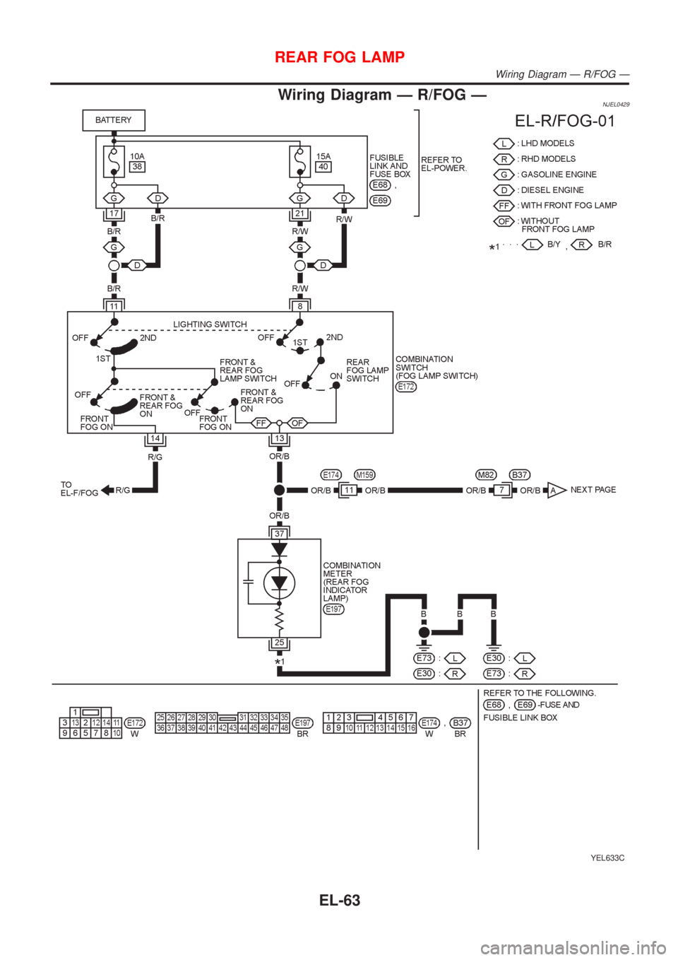
Wiring Diagram Ð R/FOG ÐNJEL0429
YEL633C
REAR FOG LAMP
Wiring Diagram Ð R/FOG Ð
EL-63
Page 2176 of 2493
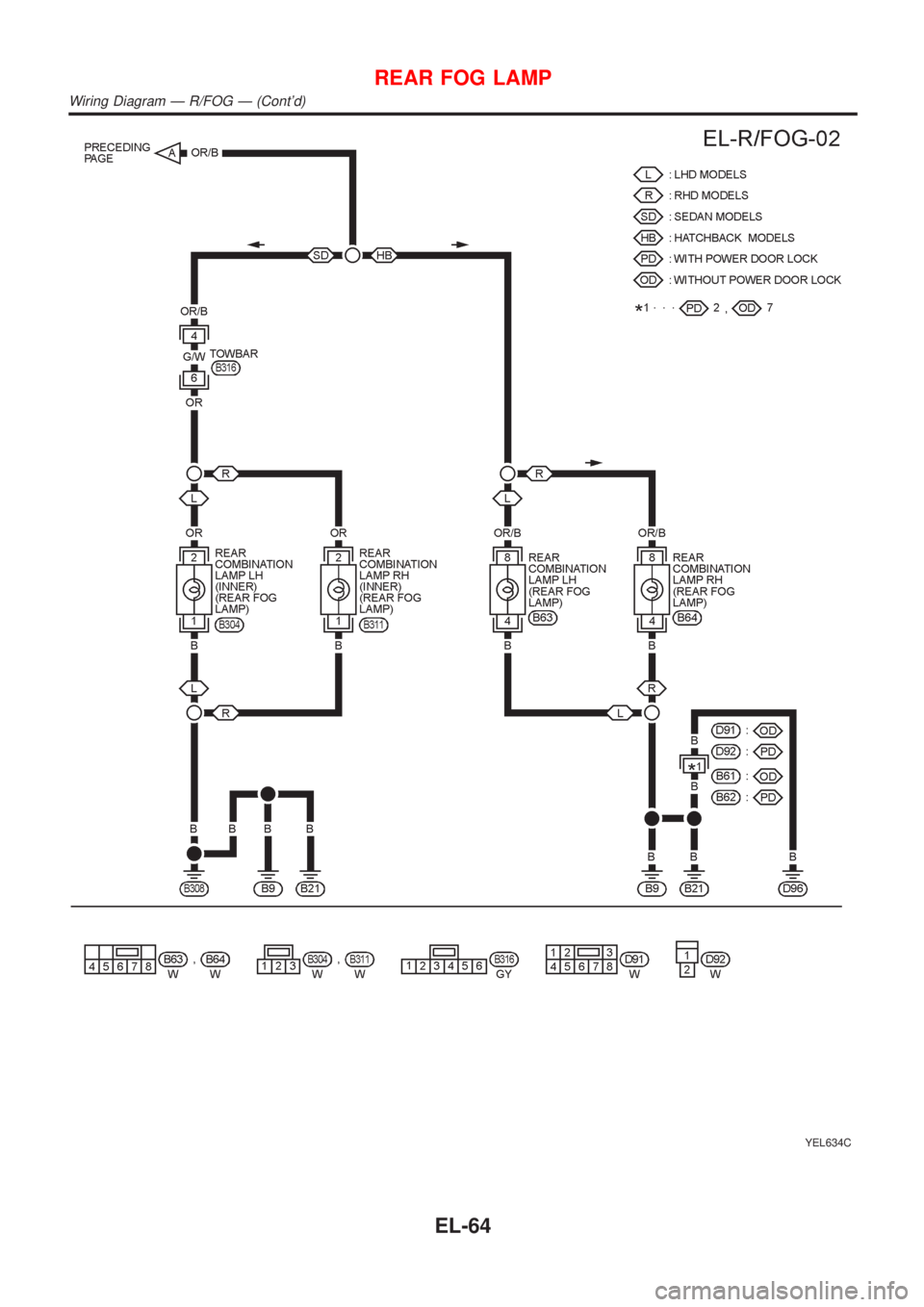
YEL634C
REAR FOG LAMP
Wiring Diagram Ð R/FOG Ð (Cont'd)
EL-64