Page 2182 of 2493
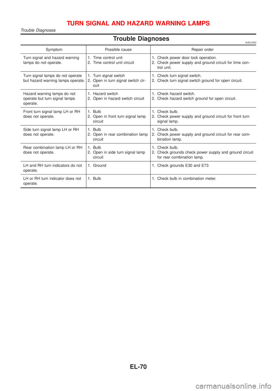
Trouble DiagnosesNJEL0432
Symptom Possible cause Repair order
Turn signal and hazard warning
lamps do not operate.1. Time control unit
2. Time control unit circuit1. Check power door lock operation.
2. Check power supply and ground circuit for time con-
trol unit.
Turn signal lamps do not operate
but hazard warning lamps operate.1. Turn signal switch
2. Open in turn signal switch cir-
cuit1. Check turn signal switch.
2. Check turn signal switch ground for open circuit.
Hazard warning lamps do not
operate but turn signal lamps
operate.1. Hazard switch
2. Open in hazard switch circuit1. Check hazard switch.
2. Check hazard switch ground for open circuit.
Front turn signal lamp LH or RH
does not operate.1. Bulb
2. Open in front turn signal lamp
circuit1. Check bulb.
2. Check power supply and ground circuit for front turn
signal lamp.
Side turn signal lamp LH or RH
does not operate.1. Bulb
2. Open in rear combination lamp
circuit1. Check bulb.
2. Check power supply and ground circuit for rear com-
bination lamp.
Rear combination lamp LH or RH
does not operate.1. Bulb
2. Open in side turn signal lamp
circuit1. Check bulb.
2. Check grounds check power supply and ground circuit
for rear combination lamp.
LH and RH turn indicators do not
operate.1. Ground 1. Check grounds E30 and E73
LH or RH turn indicator does not
operate.1. Bulb 1. Check bulb in combination meter.
TURN SIGNAL AND HAZARD WARNING LAMPS
Trouble Diagnoses
EL-70
Page 2189 of 2493
+driver's door is locked,
+driver's door is opened, or
+ignition switch is turned ON.
ON-OFF CONTROLNJEL0435S04When the driver side door, front passenger door, rear LH or RH door is opened, the interior room lamp turns
on while the interior room lamp switch is in the ªDOORº position.
BATTERY SAVERNJEL0435S11The interior room lamp is turned OFF automatically with the lamp switch in the ªDOORº position after about
30 minutes, if the lamp remains lit by the door switch open signal.
INTERIOR ROOM LAMP
System Description/ With Interior Room Lamp Timer (Cont'd)
EL-77
Page 2250 of 2493
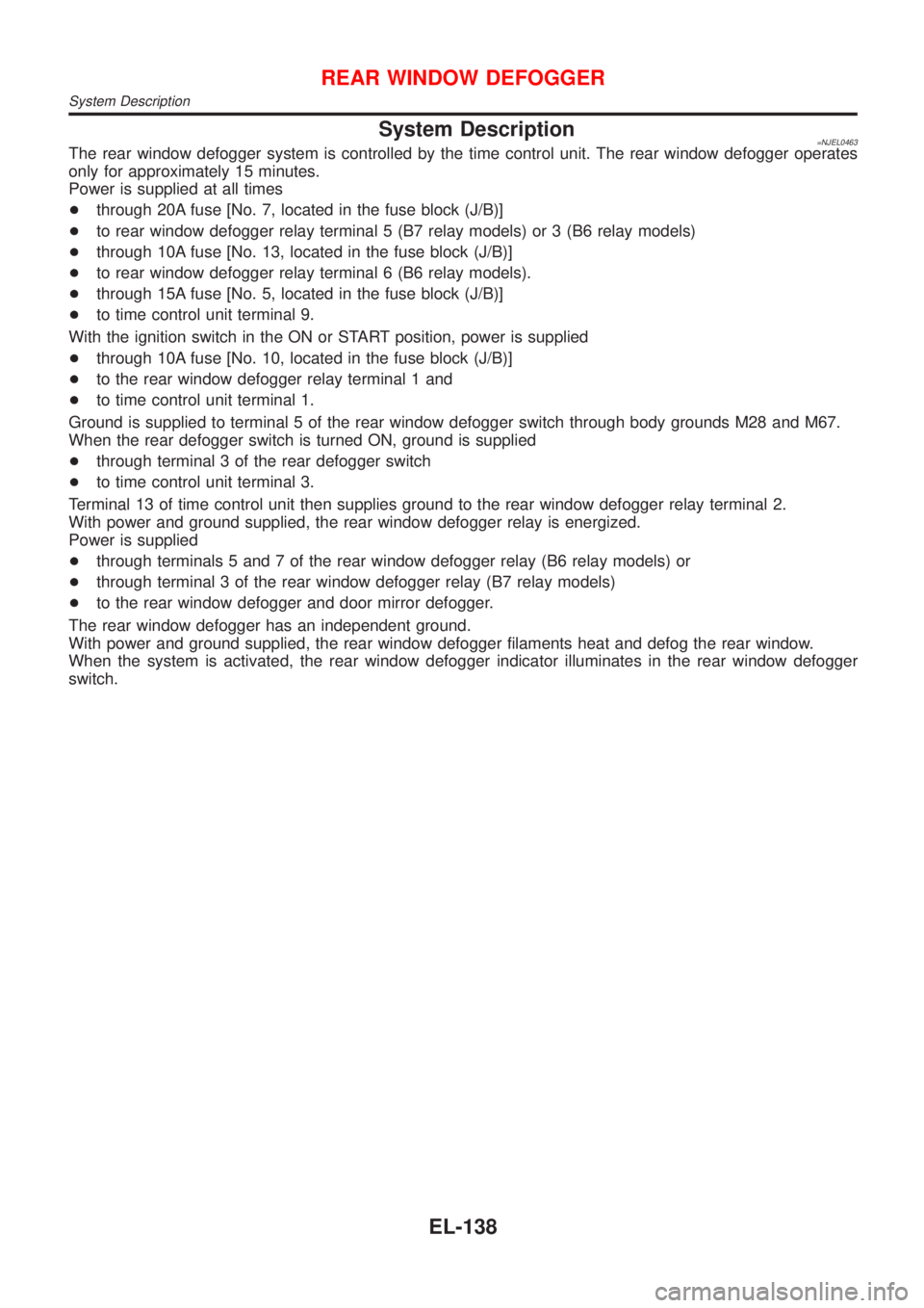
System Description=NJEL0463The rear window defogger system is controlled by the time control unit. The rear window defogger operates
only for approximately 15 minutes.
Power is supplied at all times
+through 20A fuse [No. 7, located in the fuse block (J/B)]
+to rear window defogger relay terminal 5 (B7 relay models) or 3 (B6 relay models)
+through 10A fuse [No. 13, located in the fuse block (J/B)]
+to rear window defogger relay terminal 6 (B6 relay models).
+through 15A fuse [No. 5, located in the fuse block (J/B)]
+to time control unit terminal 9.
With the ignition switch in the ON or START position, power is supplied
+through 10A fuse [No. 10, located in the fuse block (J/B)]
+to the rear window defogger relay terminal 1 and
+to time control unit terminal 1.
Ground is supplied to terminal 5 of the rear window defogger switch through body grounds M28 and M67.
When the rear defogger switch is turned ON, ground is supplied
+through terminal 3 of the rear defogger switch
+to time control unit terminal 3.
Terminal 13 of time control unit then supplies ground to the rear window defogger relay terminal 2.
With power and ground supplied, the rear window defogger relay is energized.
Power is supplied
+through terminals 5 and 7 of the rear window defogger relay (B6 relay models) or
+through terminal 3 of the rear window defogger relay (B7 relay models)
+to the rear window defogger and door mirror defogger.
The rear window defogger has an independent ground.
With power and ground supplied, the rear window defogger filaments heat and defog the rear window.
When the system is activated, the rear window defogger indicator illuminates in the rear window defogger
switch.
REAR WINDOW DEFOGGER
System Description
EL-138
Page 2255 of 2493
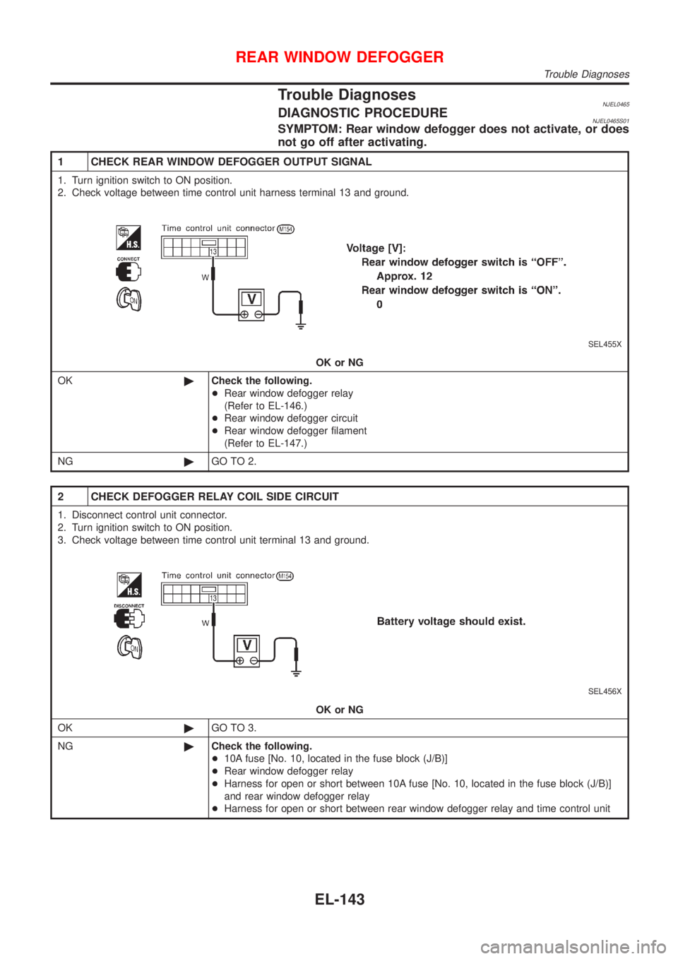
Trouble DiagnosesNJEL0465DIAGNOSTIC PROCEDURENJEL0465S01SYMPTOM: Rear window defogger does not activate, or does
not go off after activating.
1 CHECK REAR WINDOW DEFOGGER OUTPUT SIGNAL
1. Turn ignition switch to ON position.
2. Check voltage between time control unit harness terminal 13 and ground.
SEL455X
OK or NG
OK©Check the following.
+Rear window defogger relay
(Refer to EL-146.)
+Rear window defogger circuit
+Rear window defogger filament
(Refer to EL-147.)
NG©GO TO 2.
2 CHECK DEFOGGER RELAY COIL SIDE CIRCUIT
1. Disconnect control unit connector.
2. Turn ignition switch to ON position.
3. Check voltage between time control unit terminal 13 and ground.
SEL456X
OK or NG
OK©GO TO 3.
NG©Check the following.
+10A fuse [No. 10, located in the fuse block (J/B)]
+Rear window defogger relay
+Harness for open or short between 10A fuse [No. 10, located in the fuse block (J/B)]
and rear window defogger relay
+Harness for open or short between rear window defogger relay and time control unit
REAR WINDOW DEFOGGER
Trouble Diagnoses
EL-143
Page 2259 of 2493
SEL263
Filament Check=NJEL00771. Attach probe circuit tester (in volt range) to middle portion of
each filament.
SEL122R
+When measuring voltage, wrap tin foil around the top of
the negative probe. Then press the foil against the wire
with your finger.
SEL265
2. If a filament is burned out, circuit tester registers 0 or 12 volts.
SEL266
3. To locate burned out point, move probe to left and right along
filament. Test needle will swing abruptly when probe passes
the point.
REAR WINDOW DEFOGGER
Filament Check
EL-147
Page 2260 of 2493
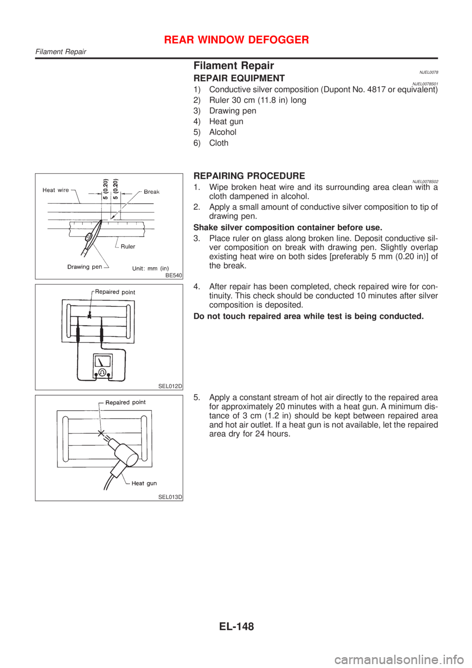
Filament RepairNJEL0078REPAIR EQUIPMENTNJEL0078S011) Conductive silver composition (Dupont No. 4817 or equivalent)
2) Ruler 30 cm (11.8 in) long
3) Drawing pen
4) Heat gun
5) Alcohol
6) Cloth
BE540
REPAIRING PROCEDURENJEL0078S021. Wipe broken heat wire and its surrounding area clean with a
cloth dampened in alcohol.
2. Apply a small amount of conductive silver composition to tip of
drawing pen.
Shake silver composition container before use.
3. Place ruler on glass along broken line. Deposit conductive sil-
ver composition on break with drawing pen. Slightly overlap
existing heat wire on both sides [preferably 5 mm (0.20 in)] of
the break.
SEL012D
4. After repair has been completed, check repaired wire for con-
tinuity. This check should be conducted 10 minutes after silver
composition is deposited.
Do not touch repaired area while test is being conducted.
SEL013D
5. Apply a constant stream of hot air directly to the repaired area
for approximately 20 minutes with a heat gun. A minimum dis-
tance of 3 cm (1.2 in) should be kept between repaired area
and hot air outlet. If a heat gun is not available, let the repaired
area dry for 24 hours.
REAR WINDOW DEFOGGER
Filament Repair
EL-148
Page 2341 of 2493
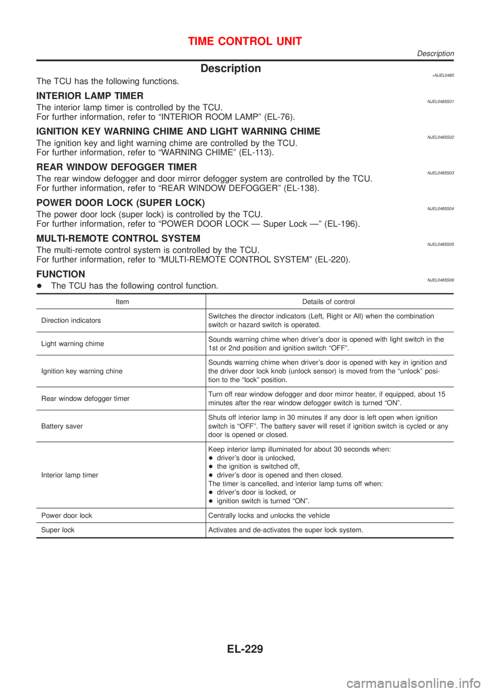
Description=NJEL0485The TCU has the following functions.
INTERIOR LAMP TIMERNJEL0485S01The interior lamp timer is controlled by the TCU.
For further information, refer to ªINTERIOR ROOM LAMPº (EL-76).
IGNITION KEY WARNING CHIME AND LIGHT WARNING CHIMENJEL0485S02The ignition key and light warning chime are controlled by the TCU.
For further information, refer to ªWARNING CHIMEº (EL-113).
REAR WINDOW DEFOGGER TIMERNJEL0485S03The rear window defogger and door mirror defogger system are controlled by the TCU.
For further information, refer to ªREAR WINDOW DEFOGGERº (EL-138).
POWER DOOR LOCK (SUPER LOCK)NJEL0485S04The power door lock (super lock) is controlled by the TCU.
For further information, refer to ªPOWER DOOR LOCK Ð Super Lock к (EL-196).
MULTI-REMOTE CONTROL SYSTEMNJEL0485S05The multi-remote control system is controlled by the TCU.
For further information, refer to ªMULTI-REMOTE CONTROL SYSTEMº (EL-220).
FUNCTIONNJEL0485S06+The TCU has the following control function.
Item Details of control
Direction indicatorsSwitches the director indicators (Left, Right or All) when the combination
switch or hazard switch is operated.
Light warning chimeSounds warning chime when driver's door is opened with light switch in the
1st or 2nd position and ignition switch ªOFFº.
Ignition key warning chineSounds warning chime when driver's door is opened with key in ignition and
the driver door lock knob (unlock sensor) is moved from the ªunlockº posi-
tion to the ªlockº position.
Rear window defogger timerTurn off rear window defogger and door mirror heater, if equipped, about 15
minutes after the rear window defogger switch is turned ªONº.
Battery saverShuts off interior lamp in 30 minutes if any door is left open when ignition
switch is ªOFFº. The battery saver will reset if ignition switch is cycled or any
door is opened or closed.
Interior lamp timerKeep interior lamp illuminated for about 30 seconds when:
+driver's door is unlocked,
+the ignition is switched off,
+driver's door is opened and then closed.
The timer is cancelled, and interior lamp turns off when:
+driver's door is locked, or
+ignition switch is turned ªONº.
Power door lock Centrally locks and unlocks the vehicle
Super lock Activates and de-activates the super lock system.
TIME CONTROL UNIT
Description
EL-229
Page 2342 of 2493
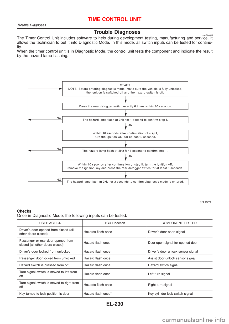
Trouble Diagnoses=NJEL0486The Timer Control Unit includes software to help during development testing, manufacturing and service. It
allows the technician to put it into Diagnostic Mode. In this mode, all switch inputs can be tested for continu-
ity.
When the timer control unit is in Diagnostic Mode, the control unit tests the component and indicate the result
by the hazard lamp flashing.
SEL496X
Checks
Once in Diagnostic Mode, the following inputs can be tested.
USER ACTION TCU Reaction COMPONENT TESTED
Driver's door opened from closed (all
other doors closed)Hazards flash once Driver's door open signal
Passenger or rear door opened from
closed (all other doors closed)Hazard flash once Door open signal for opened door
Driver's door locked from unlocked Hazard flash once Driver's door unlock sensor signal
Passenger door locked from unlocked Hazard flash once Assist door unlock sensor signal
Hazard switch is pressed from off Hazard flash once Hazard switch signal
Turn signal switch is moved to left from
offHazard flash once Left turn signal
Turn signal switch is moved to right from
offHazards flash once Right turn signal
Key turned to lock position is door Hazard flash once* Key cylinder lock switch signal
TIME CONTROL UNIT
Trouble Diagnoses
EL-230