2001 NISSAN ALMERA N16 rear lam
[x] Cancel search: rear lamPage 432 of 2493
![NISSAN ALMERA N16 2001 Electronic Repair Manual TERMI-
NAL
NO.WIRE
COLORITEM CONDITION DATA (DC Voltage)
42 G/OR PNP switch[Ignition switch ªONº]
+Gear position is ªNeutral positionº (M/T mod-
els)
+Gear position is ªPº or ªNº (A/T models)A NISSAN ALMERA N16 2001 Electronic Repair Manual TERMI-
NAL
NO.WIRE
COLORITEM CONDITION DATA (DC Voltage)
42 G/OR PNP switch[Ignition switch ªONº]
+Gear position is ªNeutral positionº (M/T mod-
els)
+Gear position is ªPº or ªNº (A/T models)A](/manual-img/5/57351/w960_57351-431.png)
TERMI-
NAL
NO.WIRE
COLORITEM CONDITION DATA (DC Voltage)
42 G/OR PNP switch[Ignition switch ªONº]
+Gear position is ªNeutral positionº (M/T mod-
els)
+Gear position is ªPº or ªNº (A/T models)Approximately 0V
[Ignition switch ªONº]
+Except the above gear positionA/T models
BATTERY VOLTAGE
(11 - 14V)
M/T models
Approximately 5V
43 B/R Ignition switch[Ignition switch ªOFFº]0V
[Ignition switch ªONº]BATTERY VOLTAGE
(11 - 14V)
44 L/R Air conditioner switch[Engine is running]
+Both air conditioner switch and blower switch
are ªONº (Compressor operates)Approximately 0V
[Engine is running]
+Air conditioner switch is ªOFFºApproximately 5V
46 PU/WPower steering oil pres-
sure switch[Engine is running]
+Steering wheel is fully turnedApproximately 0V
[Engine is running]
+Steering wheel is not turnedApproximately 5V
48 B ECM ground[Engine is running]
+Idle speedEngine ground
50 L/BElectrical load signal
(Headlamp and
Rear defogger)[Engine is running]
+Headlamp switch or rear defogger switch is
ªONºBATTERY VOLTAGE
(11 - 14V)
[Engine is running]
+Headlamp switch and rear defogger switch
are ªOFFºApproximately 0V
51 LG/B Blower fan SW[Ignition switch ªONº]
+Blower fan switch is ªONºApproximately 0V
[Ignition switch ªONº]
+Blower fan switch is ªOFFºApproximately 5V
54 Y/R A/T signal No. 1[Engine is running]
+Idle speedApproximately 0V
55 Y/G A/T signal No. 2[Engine is running]
+Idle speedApproximately 0V
56 G/Y A/T signal No. 4[Engine is running]
+Idle speedApproximately 0V
57 B ECM ground[Engine is running]
+Idle speedEngine ground
58 B Sensors' ground[Engine is running]
+Warm-up condition
+Idle speedApproximately 0V
TROUBLE DIAGNOSIS Ð GENERAL DESCRIPTIONQG
ECM Terminals and Reference Value (Cont'd)
EC-136
Page 781 of 2493
7 CHECK REAR WINDOW DEFOGGER INPUT SIGNAL CIRCUIT
1. Disconnect ECM harness connector.
2. Disconnect time control unit harness connector.
3. Check harness continuity between ECM terminal 50 and time control unit harness connector terminal 14.
Refer to wiring diagram.
4. Also check harness for short to ground and short to power.
OK or NG
OK©Refer to EL-229, ªTIME CONTROL UNITº.
NG©GO TO 8.
8 DETECT MALFUNCTIONING PART
Check the following.
+Harness connectors M63, F102
+Harness open and short between ECM and time control unit connectors
©Repair open circuit or short to ground or short to power in harness or connectors.
9 CHECK HEADLAMP FUNCTION
1. Start engine.
2. Turn the lighting switch ªONº.
3. Check that headlamps are illuminated.
Do the headlamps illuminate in both ªHighº and ªLowº positions?
YesorNo
Ye s©GO TO 11.
No©Refer to EL-40, ªHEADLAMP SYSTEMº.
10 CHECK HEADLAMP FUNCTION
1. Start engine.
2. Turn the lighting switch ªONº.
3. Check that headlamps are illuminated.
OK or NG
OK©GO TO 11.
NG©Refer to EL-40, ªHEADLAMP SYSTEMº.
ELECTRICAL LOAD SIGNALQG
Diagnostic Procedure Ð Load Signal Ð (Cont'd)
EC-485
Page 806 of 2493
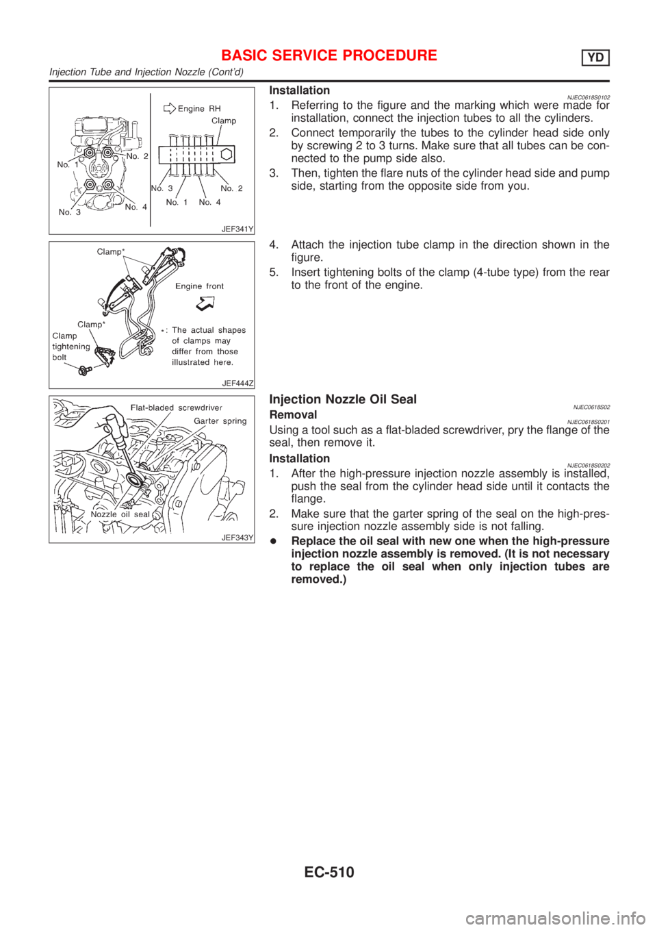
JEF341Y
InstallationNJEC0618S01021. Referring to the figure and the marking which were made for
installation, connect the injection tubes to all the cylinders.
2. Connect temporarily the tubes to the cylinder head side only
by screwing 2 to 3 turns. Make sure that all tubes can be con-
nected to the pump side also.
3. Then, tighten the flare nuts of the cylinder head side and pump
side, starting from the opposite side from you.
JEF444Z
4. Attach the injection tube clamp in the direction shown in the
figure.
5. Insert tightening bolts of the clamp (4-tube type) from the rear
to the front of the engine.
JEF343Y
Injection Nozzle Oil SealNJEC0618S02RemovalNJEC0618S0201Using a tool such as a flat-bladed screwdriver, pry the flange of the
seal, then remove it.
Installation
NJEC0618S02021. After the high-pressure injection nozzle assembly is installed,
push the seal from the cylinder head side until it contacts the
flange.
2. Make sure that the garter spring of the seal on the high-pres-
sure injection nozzle assembly side is not falling.
+Replace the oil seal with new one when the high-pressure
injection nozzle assembly is removed. (It is not necessary
to replace the oil seal when only injection tubes are
removed.)
BASIC SERVICE PROCEDUREYD
Injection Tube and Injection Nozzle (Cont'd)
EC-510
Page 815 of 2493
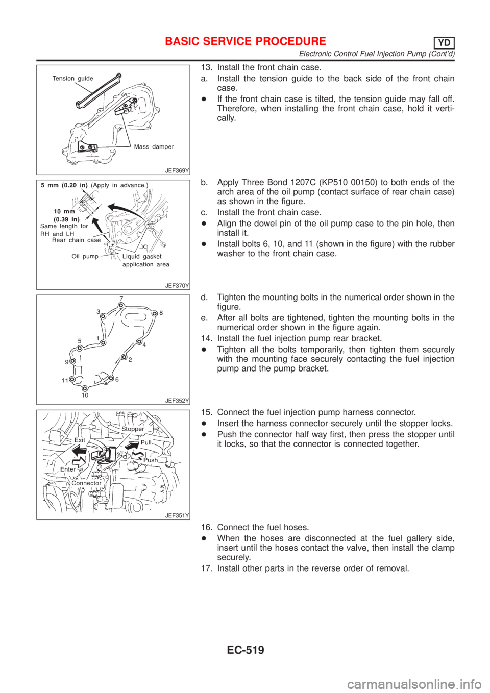
JEF369Y
13. Install the front chain case.
a. Install the tension guide to the back side of the front chain
case.
+If the front chain case is tilted, the tension guide may fall off.
Therefore, when installing the front chain case, hold it verti-
cally.
JEF370Y
b. Apply Three Bond 1207C (KP510 00150) to both ends of the
arch area of the oil pump (contact surface of rear chain case)
as shown in the figure.
c. Install the front chain case.
+Align the dowel pin of the oil pump case to the pin hole, then
install it.
+Install bolts 6, 10, and 11 (shown in the figure) with the rubber
washer to the front chain case.
JEF352Y
d. Tighten the mounting bolts in the numerical order shown in the
figure.
e. After all bolts are tightened, tighten the mounting bolts in the
numerical order shown in the figure again.
14. Install the fuel injection pump rear bracket.
+Tighten all the bolts temporarily, then tighten them securely
with the mounting face securely contacting the fuel injection
pump and the pump bracket.
JEF351Y
15. Connect the fuel injection pump harness connector.
+Insert the harness connector securely until the stopper locks.
+Push the connector half way first, then press the stopper until
it locks, so that the connector is connected together.
16. Connect the fuel hoses.
+When the hoses are disconnected at the fuel gallery side,
insert until the hoses contact the valve, then install the clamp
securely.
17. Install other parts in the reverse order of removal.
BASIC SERVICE PROCEDUREYD
Electronic Control Fuel Injection Pump (Cont'd)
EC-519
Page 832 of 2493
Basic InspectionNJEC0632Precaution:
Perform Basic Inspection without electrical or mechanical
loads applied;
+Headlamp switch is OFF,
+On vehicles equipped with daytime light systems, set
lighting switch to the 1st position to light only small
lamps.
+Air conditioner switch is OFF,
+Rear defogger switch is OFF,
+Steering wheel is in the straight-ahead position, etc.
1 INSPECTION START
1. Check service records for any recent repairs that may indicate a related problem.
2. Check the current need for scheduled maintenance, especially for fuel filter and air cleaner filter. Refer to MA-4, ªPeri-
odic Maintenanceº.
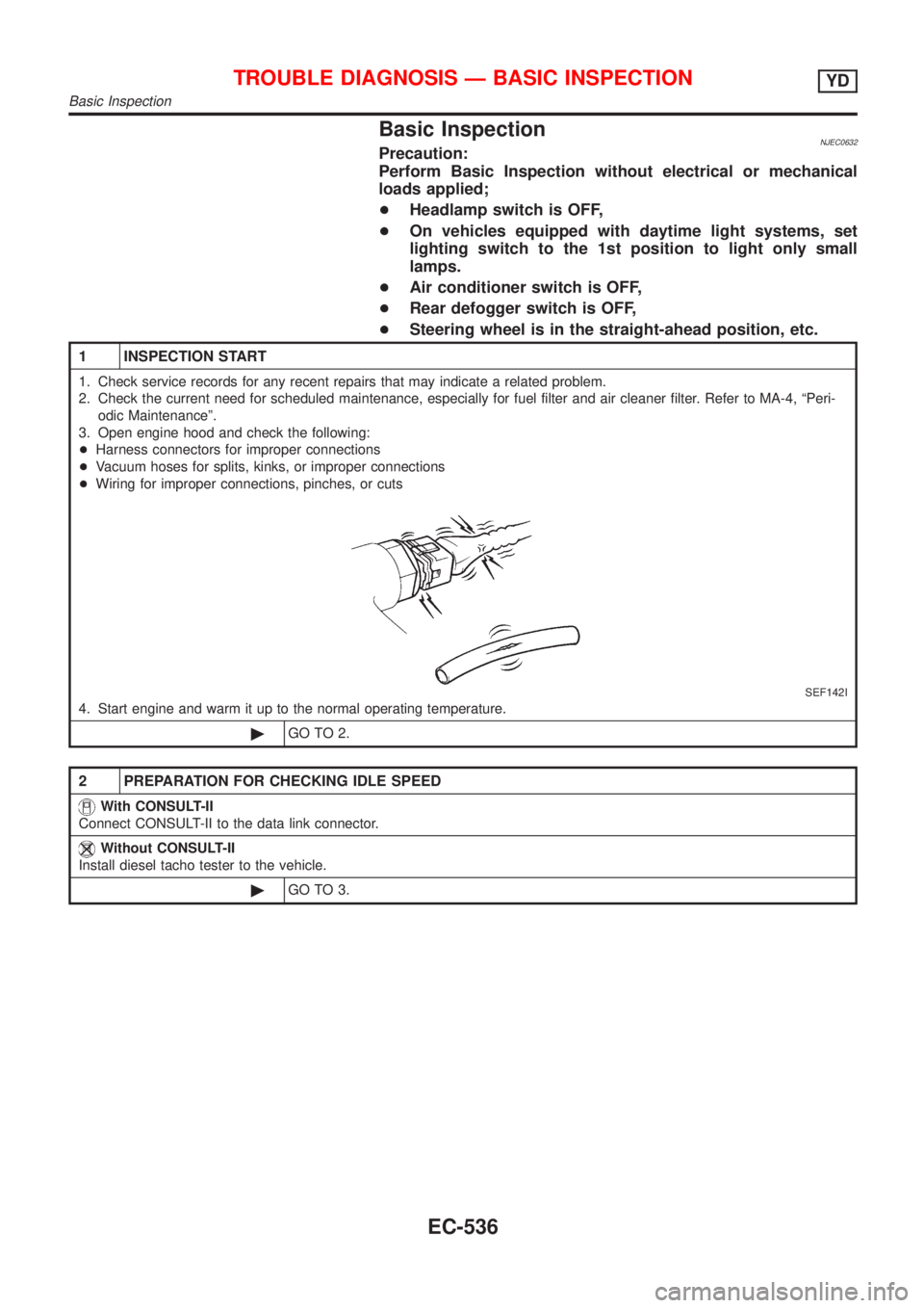
3. Open engine hood and check the following:
+Harness connectors for improper connections
+Vacuum hoses for splits, kinks, or improper connections
+Wiring for improper connections, pinches, or cuts
SEF142I
4. Start engine and warm it up to the normal operating temperature.
©GO TO 2.
2 PREPARATION FOR CHECKING IDLE SPEED
With CONSULT-II
Connect CONSULT-II to the data link connector.
Without CONSULT-II
Install diesel tacho tester to the vehicle.
©GO TO 3.
TROUBLE DIAGNOSIS Ð BASIC INSPECTIONYD
Basic Inspection
EC-536
Page 1073 of 2493
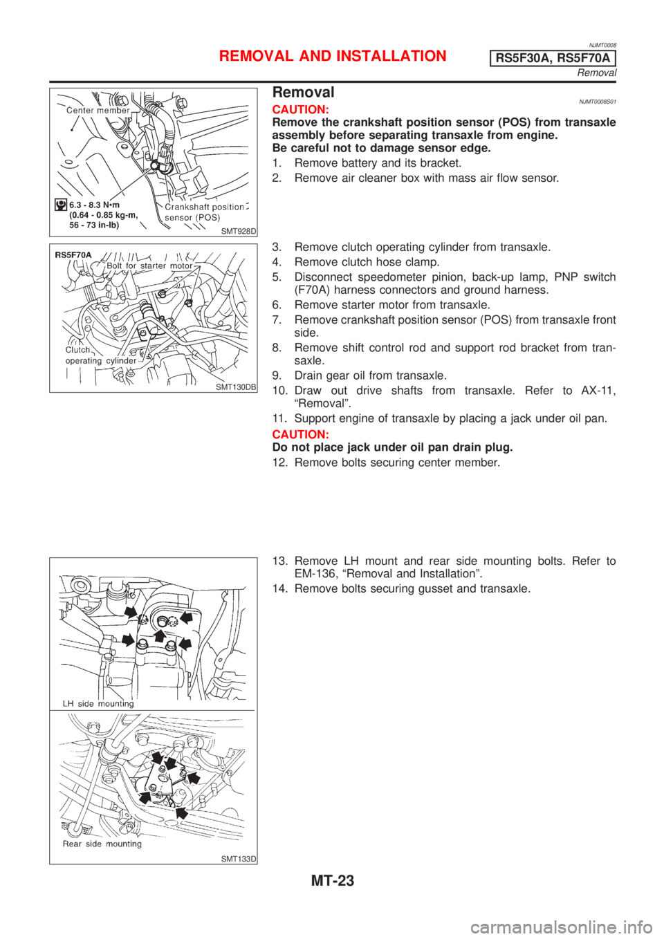
NJMT0008
SMT928D
RemovalNJMT0008S01CAUTION:
Remove the crankshaft position sensor (POS) from transaxle
assembly before separating transaxle from engine.
Be careful not to damage sensor edge.
1. Remove battery and its bracket.
2. Remove air cleaner box with mass air flow sensor.
SMT130DB
3. Remove clutch operating cylinder from transaxle.
4. Remove clutch hose clamp.
5. Disconnect speedometer pinion, back-up lamp, PNP switch
(F70A) harness connectors and ground harness.
6. Remove starter motor from transaxle.
7. Remove crankshaft position sensor (POS) from transaxle front
side.
8. Remove shift control rod and support rod bracket from tran-
saxle.
9. Drain gear oil from transaxle.
10. Draw out drive shafts from transaxle. Refer to AX-11,
ªRemovalº.
11. Support engine of transaxle by placing a jack under oil pan.
CAUTION:
Do not place jack under oil pan drain plug.
12. Remove bolts securing center member.
SMT133D
13. Remove LH mount and rear side mounting bolts. Refer to
EM-136, ªRemoval and Installationº.
14. Remove bolts securing gusset and transaxle.
REMOVAL AND INSTALLATIONRS5F30A, RS5F70A
Removal
MT-23
Page 1700 of 2493

Inspection - Lining .....................................................33
Installation ..................................................................33
REAR DISC BRAKE (CAM & STRUT TYPE)..............35
Component ................................................................35
Pad Replacement ......................................................35
Removal .....................................................................37
Disassembly...............................................................37
Inspection...................................................................38
CALIPER.................................................................38
ROTOR...................................................................39
Assembly ...................................................................39
Installation ..................................................................42
REAR DISC BRAKE (BALL & RAMP TYPE)..............43
Component ................................................................43
Pad Replacement ......................................................43
Removal .....................................................................45
Disassembly...............................................................45
Inspection...................................................................45
CALIPER.................................................................45
ROTOR...................................................................46
Installation ..................................................................46
PARKING BRAKE CONTROL......................................47
Components...............................................................47
Removal and Installation ...........................................47
Inspection...................................................................47
Adjustment .................................................................48
ABS
DESCRIPTION...............................................................49
Purpose......................................................................49
ABS (Anti-Lock Brake System) Operation ................49
ABS Hydraulic Circuit ................................................49
System Components .................................................50
System Description ....................................................50
SENSOR.................................................................50
CONTROL UNIT......................................................50
ABS ACTUATOR AND ELECTRIC UNIT....................50
Component Parts and Harness Connector
Location .....................................................................52
Schematic ..................................................................53
Wiring Diagram - ABS - .............................................54
ON BOARD DIAGNOSTIC SYSTEM
DESCRIPTION...............................................................58
CONSULT-II ...............................................................58
CONSULT-II APPLICATION TO ABS..........................58
ECU (ABS CONTROL UNIT) PART NUMBER
MODE
.....................................................................58
CONSULT-II Inspection Procedure............................58
SELF-DIAGNOSIS PROCEDURE..............................58
SELF-DIAGNOSTIC RESULTS MODE.......................60
DATA MONITOR PROCEDURE................................61
ACTIVE TEST PROCEDURE....................................62
DATA MONITOR MODE...........................................63
ACTIVE TEST MODE...............................................63
TROUBLE DIAGNOSIS - INTRODUCTION..................64
How to Perform Trouble Diagnoses for Quick
and Accurate Repair ..................................................64
INTRODUCTION......................................................64
TROUBLE DIAGNOSIS - BASIC INSPECTION...........65
Preliminary Check......................................................65
Ground Circuit Check ................................................68
ABS ACTUATOR AND ELECTRIC UNIT GROUND.....68
TROUBLE DIAGNOSES FOR SELF-DIAGNOSTIC
ITEMS.............................................................................69
Wheel Sensor or Rotor ..............................................69
DIAGNOSTIC PROCEDURE.....................................69
ABS Actuator Solenoid Valve or Solenoid Valve
Relay ..........................................................................72
DIAGNOSTIC PROCEDURE.....................................72
Motor Relay or Motor.................................................75
DIAGNOSTIC PROCEDURE.....................................75
Low Voltage ...............................................................77
DIAGNOSTIC PROCEDURE.....................................77
Control Unit ................................................................79
DIAGNOSTIC PROCEDURE.....................................79
TROUBLE DIAGNOSES FOR SYMPTOMS.................80
1. ABS Works Frequently ..........................................80
2. Unexpected Pedal Action ......................................80
3. Long Stopping Distance ........................................81
4. ABS Does Not Work ..............................................82
5. Pedal Vibration and Noise.....................................83
6. ABS Warning Lamp Does Not Come On
When Ignition Switch Is Turned On...........................84
7. ABS Warning Lamp Stays On When Ignition
Switch Is Turned On ..................................................86
REMOVAL AND INSTALLATION.................................88
Wheel Sensors ..........................................................88
ABS Actuator and Electric Unit..................................89
REMOVAL...............................................................89
INSTALLATION........................................................89
Sensor Rotor..............................................................90
REMOVAL...............................................................90
INSTALLATION........................................................90
SERVICE DATA AND SPECIFICATIONS (SDS).........91
General Specifications ...............................................91
Disc Brake .................................................................91
Drum Brake................................................................91
Brake Pedal ...............................................................92
Parking Brake ............................................................92
CONTENTS(Cont'd)
BR-2
Page 1745 of 2493
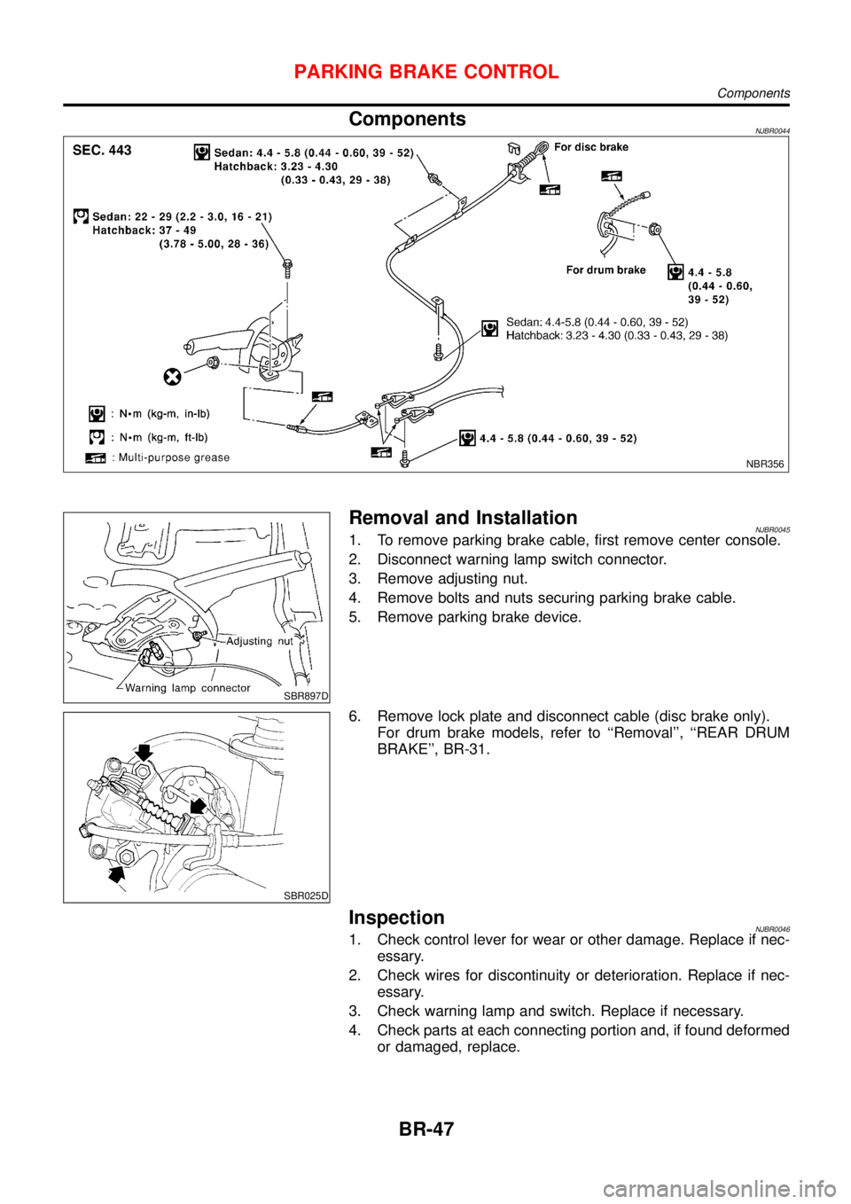
ComponentsNJBR0044
NBR356
SBR897D
Removal and InstallationNJBR00451. To remove parking brake cable, first remove center console.
2. Disconnect warning lamp switch connector.
3. Remove adjusting nut.
4. Remove bolts and nuts securing parking brake cable.
5. Remove parking brake device.
SBR025D
6. Remove lock plate and disconnect cable (disc brake only).
For drum brake models, refer to ‘‘Removal’’, ‘‘REAR DRUM
BRAKE’’, BR-31.
InspectionNJBR00461. Check control lever for wear or other damage. Replace if nec-
essary.
2. Check wires for discontinuity or deterioration. Replace if nec-
essary.
3. Check warning lamp and switch. Replace if necessary.
4. Check parts at each connecting portion and, if found deformed
or damaged, replace.
PARKING BRAKE CONTROL
Components
BR-47